




Abstract
Strengthening of structural members is a common practice around the world that may arise due to deterioration of concrete with age or upgradation of design code. This paper aims to elucidate a technique used for strengthening of the reinforced concrete beam for flexural capacity by using externally welded steel angles and steel bars. For this motive, three beams were strengthened with external steel angles and three with external steel bars. The external strengthening steel elements were attached at the bottom of the beam with shear reinforcement. Control samples without external steel angles and steel bars for comparison purposes were also prepared. All reinforced concrete beams were first constructed using a concrete ratio of 1:2:4, and then external steel elements were added to existing flexural reinforcement by using a fillet weld with tee joints having thickness and length of 5/16" (7.9 mm) and 6" (152.4 mm), respectively. Fourth point loading criteria were used to investigate the flexural capacity of beams in positive bending. All beams were designed strong enough in shear, to resist the ultimate loads without shear failure. Test results indicated that beams strengthened with this technique have an average increase of 238% with steel angles and 106% with steel bars, in load-carrying capacity than control samples. Strengthened beams showed a uniform crack pattern. Moreover, the concrete cover made a good bond with existing concrete and was strong enough to withstand ultimate loads. Conclusively, the steel angles and steel bars can be used as an external strengthening material, to enhance the flexural capacity of reinforced concrete beams.
Keywords
Introduction
Reinforced Concrete (RC) structural members are subjected to a variety of actions during their lifetime, resulting in the loss of capacity over time. Reduction in the capacity of RC structures is a result of environmentally induced degradation, overloading, inadequate maintenance, spalling of concrete causing exposure of reinforcement, and severe loading conditions such as earthquakes and blasts. Substantial laboratory experiments and organized research has been carried out on the flexural and shear behavior of Reinforced Concrete Beam (RCB) by utilizing different materials and bonding techniques. For instance, Carbon Fiber Reinforced Polymer (CFRP) sheets and epoxy mortar (Bahn and Harichandran, 2008), Glass Fiber Reinforced Polymer (GFRP) (Chiew et al., 2007), strain-hardening cement-based composite (Kim et al., 2011), longitudinal and U-shape basalt Fiber Reinforced Polymer (FRP) sheets (Chen et al., 2018), aluminum alloy plates (Rasheed et al., 2017), wire mesh-epoxy composites applied in the form of laminates (Qeshta et al., 2015), reinforced concrete beam-column joints strengthened with steel cage (Campione et al., 2015), CFRP grid-reinforced engineered cementitious composite matrix (Yang et al., 2018), and hybrid carbon sheets (Zhang et al., 2017) have been used as a mean of improving the performance of RC structural members. However, each technique has some limitations, material availability issues, and implementation problems. As per the authors’ knowledge, the problem of successful implementation of these available strengthening materials still exists, and therefore there is a growing interest to develop effective strengthening techniques that are easy to implement, utilize locally available resources and offer the desired strength enhancement.
In order to develop efficient and large-scale implementable strengthening technique, various researchers conducted experimental investigations and concluded significant results. Recently, Cazacu et al. (2017) studied the flexural capacity of RC beam, strengthened with CFRP material, and reported an average increase of 35–40% in the flexural strength of the strengthened specimen in comparison to that of control specimen. The authors’ found CFRP as an effective strengthening material that presented remarkable shear crack arresting ability and consequently resulted in a transition of the failure mode from shear critical to flexural critical. However, the strengthened specimen experienced loss in ductility in comparison to the reference RCB. Similarly, D’Ambrisi and Focacci (2011) investigated flexural strength enhancement in RC members externally bonded with Fiber Reinforced Cementitious Matrix (FRCM) and reported an approximate enhancement of 30% in the load-carrying capacity of strengthened specimens. However, the failure occurred due to debonding of FRCM. Another experimental study (Gonzalez-Libreros et al., 2017) assessed the shear capacity and crack pattern of RCB bonded with FRP and FRCM. The use of this technique showed a successful increase in the shear capacity of the strengthened RCB, however, debonding of FRP jackets was reported. The use of carbon FRCM in multi layers is found to be successful in the strength enhancement of RCB. For instance, Ebead et al. (2017) reported substantial improvement of 77% in the flexural strength of RCB strengthened with carbon FRCM in three layers. Similarly, Aljazaeri and Myers (2017) reported a successful increase of 60% in the load-carrying capacity of FRCM reinforced concrete members. Another experimental study (Chen and Cheng, 2017) analytically demonstrated that FRP bonded sheets successfully enhanced the flexural strength of the RCB. However, the mode of failure depends upon the technique adopted for wrapping sheets and mechanical properties of the epoxy used. Some other researches concluded that the plate bonding technique is an effective way to improve the flexural capacity of RCB (Yang et al., 2018), and the flexural response of steel-FRCM composites can be enhanced by 15–21% (Sneed et al., 2016). Gul et al. (2015) performed experimental research on the flexural strength enhancement of RCB by using externally bonded steel angles and steel bars and concluded that the capacity of the strengthened specimen in terms of strength and ductility is greatly enhanced, however, the failure occurred due to debonding of external steel. Among all these researches, the failure of the strengthened specimen was common and was caused by the delamination of bonded materials or sheets. The performance of strengthened reinforced concrete members can be significantly improved in terms of strength and ductility if adequate bonding between the structural member and strengthening material is ensured.
This study was carried out after an extensive literature review while having established inadequacy of the previously adopted strengthening techniques wherein debonding of the strengthening material and the structural member was reported (Gul et al., 2015). In order to prevent the delamination of external steel, both steel angles and steel bars were provided along the whole supporting length of the beam via welding technique. All specimens were tested in positive bending under the fourth point bend test in the laboratory, and the results were analyzed in detail. The flexural strengthening technique of existing RCB via welded external steel is an effective, easily implementable, and yields satisfactory results by improving the failure mechanism in terms of crack pattern.
Materials and methods
Concrete
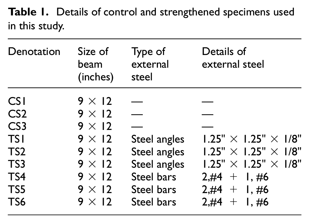
In this research work, three types of reinforced concrete specimens were constructed. Details of these specimens are given in Table 1. All concrete specimens were constructed from the same batch, prepared from Ordinary Portland Cement (OPC) Type 1 conforming to ASTM C150/C150M-12 (2012), having a specific gravity of 3.15. Natural fine and coarse aggregate were acquired from the local source conforming to the ASTM C33-03 (2003). Each specimen was prepared with cement, fine aggregate, and coarse aggregate in the ratio of 1:2:4, which is a normal mix design adopted in the field of construction in Pakistan. The water-cement ratio of 0.5 was used. To determine the compressive strength of the mix design, three cylindrical specimens having diameter and length dimensions of 6'' (152.4 mm) and 12'' (304.8 mm), respectively, were prepared from the same batch and were tested under compression loading at the age of 28 days as per standards of ASTM C39 (2015). The average compressive strength obtained was 2900 psi (20MPa), which is well above the ACI strength requirements of structural normal weight concrete (ACI Committee 318-19, 2019).
Details of control and strengthened specimens used in this study.
Reinforcement
Minimum flexural reinforcement was provided to allow the beam for flexural failure while preventing shear failure by providing maximum shear reinforcement as per the ACI Committee 318-19 (2019) specifications. For strengthening purpose, grade 40 steel angles having equal legs of 1.25 inch (31.7 mm) and thickness of 1/8 inch (3.1 mm), and grade 40 steel bars were acquired from the locally available market in the present research work. These steel angles and steel bars were welded to the bottom face of the RC beam stirrups as per the design specifications. The authors of the present study successfully implemented this technique in their previous research work and reported significant improvement in the flexural strength of RC beams (
Test beam
In total, nine reinforced concrete beams were constructed using the materials mentioned in Section 2.1. Three specimens, namely CS1, CS2, and CS3 designed and constructed as conventional RCB, were used as control specimens. The remaining six beams were strengthened in flexure, of which three beams were externally strengthened using steel angles designated as TS1, TS2, and TS3, and other three were externally strengthened with steel bars designated as TS4, TS5, and TS6. The width and overall depth of the beams were selected as 9" and 12" (228.6 mm and 304.8 mm), respectively, and the total length of the beam as 11 feet (3352.8 mm). Linear Variable Displacement Transducers (LVDTs) were linked at the bottom of beams in the maximum tension zone to gauge the deflections. This setup leads to determine displacement at the region of maximum expected deflection at different load stages. The dimensions of beam, reinforcement limitation, splices, and stirrups details were determined using the ACI standard specifications (ACI Committee 318-19, 2019). Details of the control specimen are shown in Figure 1(a) and (b), while the details of beams strengthened with external steel angles and steel bars are shown in Figure 2 (a) and (b) and Figure 3(a) and (b), respectively.
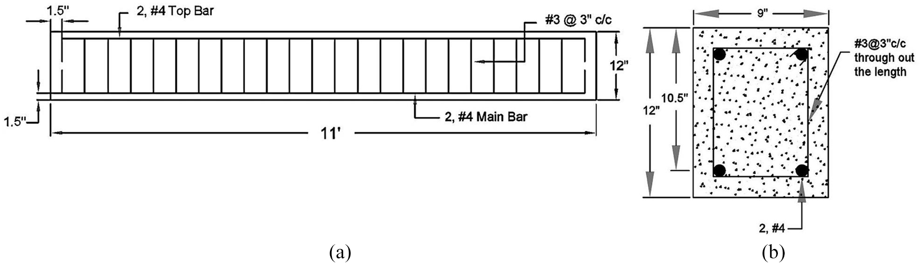
(a) Longitudinal section and (b) cross section of control specimen.
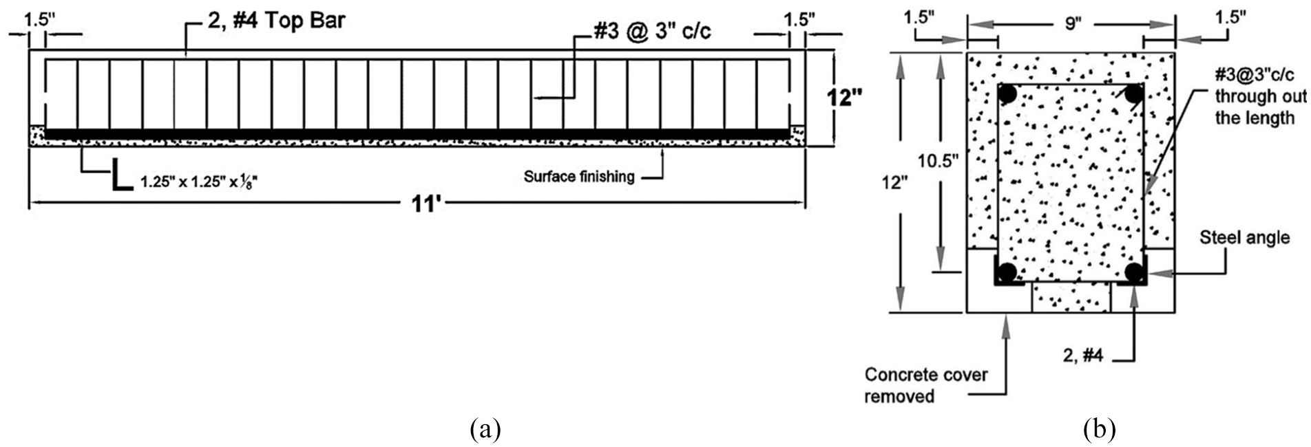
(a) Longitudinal section and (b) cross section of beam strengthened with external steel angles.
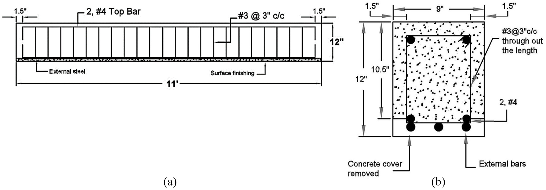
(a) Longitudinal section and (b) cross section of beam strengthened with external steel bars.
Welding details
The external steel angles and steel bars were attached to the bottom face of the stirrups of existing RCB via the welding technique. For which the design was carried out as per defined standards of the American Institute of Steel Construction (AISC) (
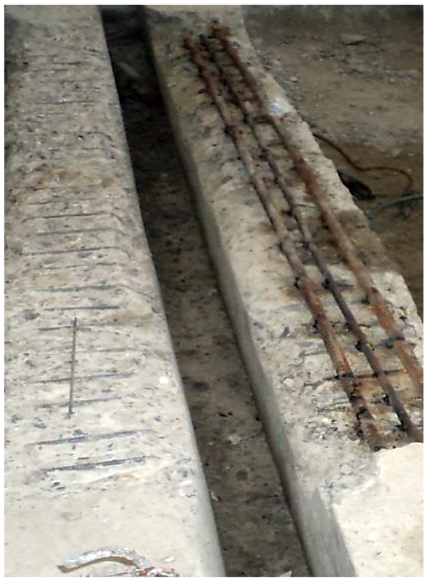
Welding external steel elements to the stirrups of the RC beams.
Testing program
To investigate the flexural behaviour, all the beams were tested under fourth point loading. The test setup made for fourth point loading on a 10 feet (3048 mm) clear span of the beam shown in Figure 5. The specimens were tested carefully through Universal Testing Machine (UTM) with 100 tons loading capacity, and sensitively captured the initiation and propagation of cracks. The loads were applied at an equal distance of 3.33 feet (1015 mm) along the length of the beam from each support.

Experimental setup for finding flexural capacity of RC beam.
Experimental results and discussion
Control specimen
Control specimens in this research refer to beams with no externally bonded steel angles or steel bars designated as CS1, CS2, and CS3. The load-displacement curve of the three control specimens is plotted in Figure 6. The beams were tested according to the fourth point loading criteria to failure. The failure of all control specimens was almost identical and failed due to the yielding of reinforcement, followed by the crushing of concrete. The beams failed in the typical flexural manner and experienced an ample amount of deflection at the moment of failure.

Load displacement relationship of control specimens.
The control specimens responded elastically at load values of 5.4 kips, 5.3 kips, and 5.5 kips, respectively, while the corresponding deflections were noted as 0.08", 0.09", 0.07", respectively. The first crack appeared at the aforementioned load and deflection values in the middle third region, where the bending moment was maximum. For the same specimens, the second crack appeared at loading values of 7.5 kips, 7.09 kips, 6.2 kips corresponding to a deflection of 0.18", 0.17", 0.10", respectively, in the middle third region of beam. The cracks formed to propagate upward in a flexural pattern, as the load was increased. With further increase in the load values, the cracks reached approximately to the depth of compression of beam in strain compatibility diagram. Beyond the point of the elastic load of 5.4 kips, 5.3 kips, and 5.4 kips, the degradation of stiffness was observed. CS1, CS2, and CS3 showed a maximum ultimate load value of 8.51 kips, 8.65 kips, and 8.98 kips, respectively.
Beams strengthened with external steel angles
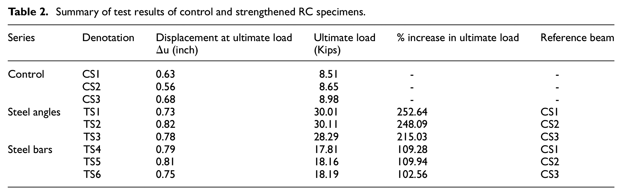
Three beams designated as TS1, TS2, and TS3 were provided with external steel angles for the flexural capacity enhancement. The load-displacement curves for these specimens are shown in Figure 7. All the specimens of this category showed favorable failure mode with uniform distribution of cracks. In TS1, the first crack was initiated at a loading value of 28.5 kips in the region of maximum bending moment. While in the case of TS2 and TS3, the first crack was observed in the same region with a loading value of 27.0 kips and 28.2 kips, respectively. The ultimate load in the flexural failure for these specimens were noticed at 30.01 kips, 30.11 kips, and 28.29 kips, respectively. The failure pattern of the strengthening beams was the same as observed for control samples in which steel yielding occurred, followed by the crushing of concrete. All the strengthened specimens of this category showed significant flexural capacity enhancement by 252.64%, 248.09%, and 215.03%, respectively, when compared with the control specimens. Summary of test results is presented in Table 2.
Summary of test results of control and strengthened RC specimens.
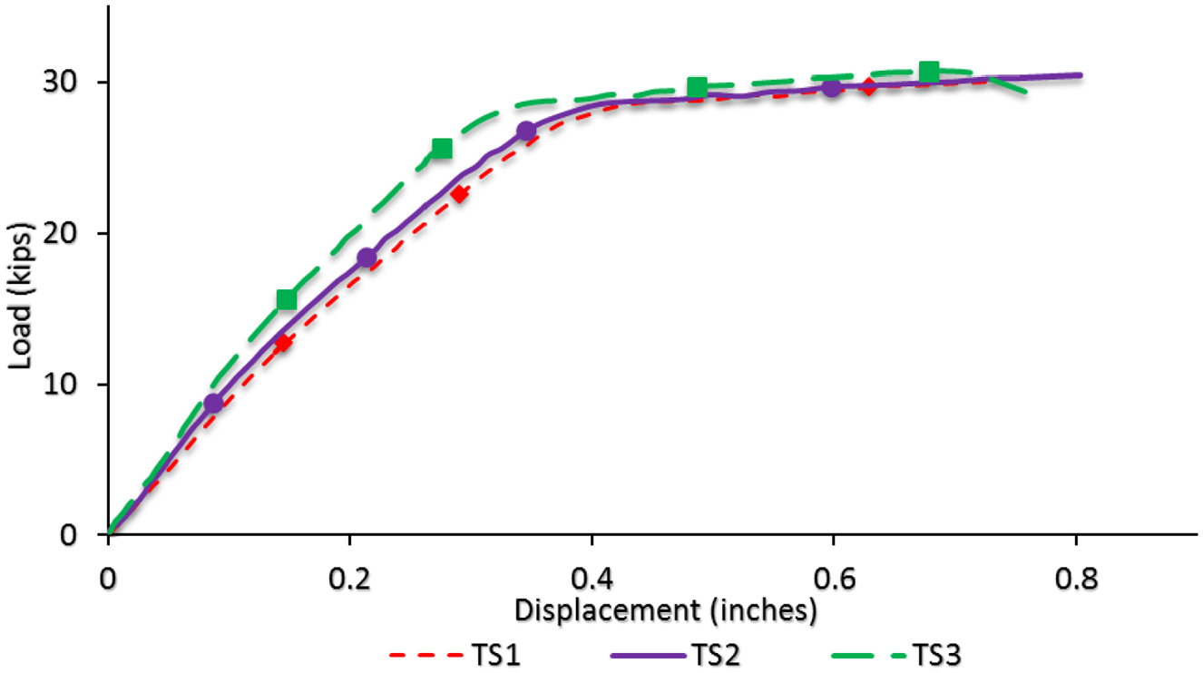
Load displacement relationship of RCB specimens strengthened with steel bars.
Beams strengthened with external steel bars
Load vs displacement curves for the steel bars strengthened specimens are shown in Figure 8. The beams strengthened with external steel bars showed an almost identical elastic response to the beams provided with external steel angles. During the initial period of loading, the beams showed elastic behavior with no or minimum cracks. In the case of TS4, the first crack initiated at a loading value of 5.79 kips corresponding to a deflection value of 0.06", while for TS5 and TS6, the same happened at loading value of 6.39 kips and 5.47 kips corresponding to deflection values of 0.08" and 0.05", respectively. As the load was further increased, the crack width appeared to be increasing from bottom to top until it reached the ultimate loading value of 17.81 kips, 18.16 kips and 18.19 kips for specimen TS4, TS5, and TS6, respectively. In comparison to the control specimen, the TS4, TS5, and TS6 showed a significant increment of 109.28%, 109.94%, and 102.56%, respectively, in the values of flexural loading. The combined load-displacement curves of all RC beams are shown in Figure 9.

Load displacement relationship of beam strengthened with external steel bars.
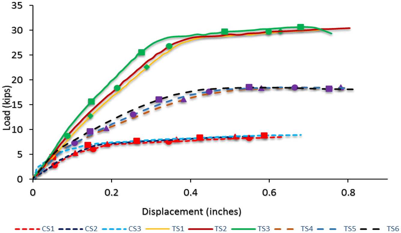
Combined load-displacement relationship of RC beams.
In previous study (Gul et al., 2015), the delamination of steel bars was reported during the loading process, which was primarily due to the cutoff of external steel bars as per the ACI standards (ACI Committee 318-19, 2019) instead of fully developed bars. However, no such phenomenon was observed in the current research study as the external steel bars were extended to a full length of beams. The external strengthening bars provided extra flexural strength to the strengthening beams. However, the failure of the external steel bar is reported at the point of welding at ultimate loading, as shown in Figure 10.
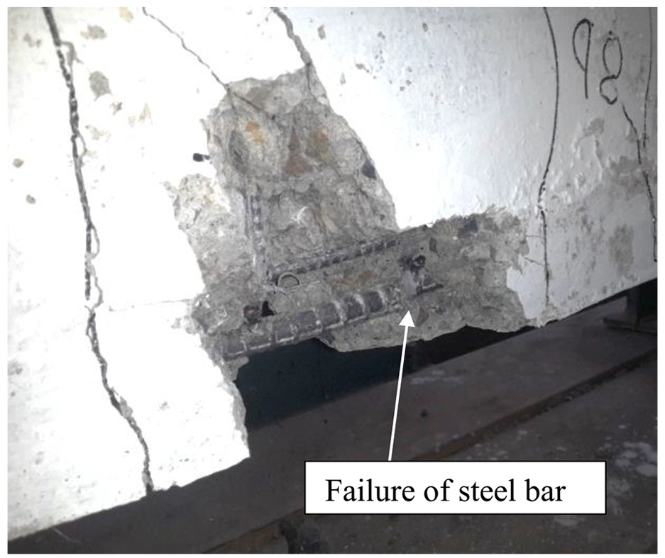
Failure of external steel bars in RC beam.
Failure pattern
The failure of control specimens is attributed to the opening of cracks by exceeding the loads until it fails at the ultimate load, as shown in Figure 11. The control specimens showed the first crack at the middle of the beam length, followed by cracks on the left and right sides, which tend to propagate upward as the load increased. The failure of all tested beams was governed by the bending of steel followed by initiation of cracks, which lead to the crushing of concrete. The beams strengthened with external steel elements showed a significant increase in its flexural capacity. Furthermore, no delamination of external steel elements was observed in any strengthened beam. Failure of the outer steel bar was noticed at the ultimate load at the point of welding. The beams showed linear elastic behavior before yielding of the flexural reinforcement, which resulted in the ductile failure of beams. Similar to control specimens, these specimens also depicted the first crack at almost the middle of the beam in maximum tension region, which progressively increased. There was no delamination of steel angles nor opening of any welding joints. The bending of steel angles occurred, followed by the crushing of concrete. The beams failed purely in the flexural manner by initiating cracks in the tension zone and widen up to the compression region of the beam as loads tend to increase. Summery of test results is shown in Table 2.
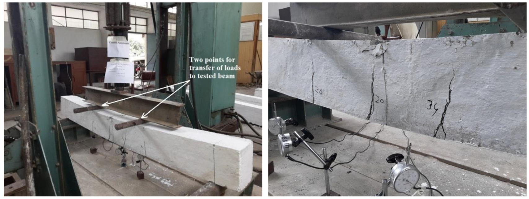
Faliure of control specimen.
Conclusions
In this research work, we encourage this effective, easily implementable, and cost-effective strengthening technique for the flexural capacity enhancement of existing RC members. Based on the test results and observations of this experimental work, the following conclusions are drawn:
The strengthened specimens, having steel angles and steel bars as external reinforcement, showed significant improvement in the flexural capacity with uniform distribution of flexural cracks.
In comparison to the control specimens, the strengthened specimens showed a favorable flexural failure mode.
The strengthened specimens having steel angles as external reinforcement showed better performance in terms of flexural capacity and was more ductile than those having steel bars as external reinforcement.
The beams strengthened with external steel angles showed almost 132% more flexural strength as compared to beams reinforced with steel bars. This may be justified as in case of external steel angles, the welding joint between outer steel and stirrups of the beam is more strong, and the area of external steel angles is concentrated on a small region as compared to external steel bars, and thus resulted in an improved flexural capacity of the RC beam.
As there was no delamination of external steel elements, therefore the welding option for attachment of external steel elements with the existing reinforcement of beam is reliable.
The finishing cover showed a good bond with the existing concrete.
The failure of steel bars at the point of welding requires more attention and further research work.
Footnotes
Declaration of conflicting interests
The author(s) declared no potential conflicts of interest with respect to the research, authorship, and/or publication of this article.
Funding
The author(s) received no financial support for the research, authorship, and/or publication of this article.
