



Abstract
Despite the proven effectiveness of tuned liquid dampers (TLDs), readily available liquid storage tanks are rarely utilized for vibration control of laterally-excited structures, as these are deep tanks with low inherent damping. Further, the fluctuation in liquid level in these tanks also causes variation in the fundamental sloshing frequency, leading to detuning. To overcome these problems, a novel TLD with floating base (TLD-FB) is proposed, in which a constant and shallow liquid level is maintained between the free liquid surface and the floating base. The liquid above the floating base acts as a conventional shallow TLD that always remains tuned to the structural frequency. The paper demonstrates how the TLD-FB can be incorporated into a water storage tank system on an example building without disturbing its functionality and achieves structural response reduction, despite water level fluctuations in the tanks.
Introduction
The tuned liquid damper (TLD) is an established vibration control device credited with reliability of performance, low-cost involvement, ease of installation and ease of amendment to design modifications. It is an inertia based passive system, in which the mass of the damper is constituted by liquid (normally water) in a container attached to the primary structure. The study on vibration control of civil engineering structures using TLD was initiated in the late 1970s (Vandiver and Mitome, 1978). Since then, the effectiveness of the TLD in mitigation of structural vibrations due to environmental loadings, such as strong wind and earthquake, is well documented by several researchers (Banerji et al., 2000; Kareem, 1993; Kareem and Sun, 1987; Lago et al., 2019; Rai et al., 2011; Soong and Spencer, 2002). There are different configurations of the TLD, such as the liquid tank damper and the liquid column damper, along with various modified forms of the latter. The vibrational energy transferred to the tank TLD through tuning between the dominant structural frequency and the first liquid sloshing frequency is dissipated through damping that chiefly arises from viscous dissipation at the solid boundaries of the container and from free surface contamination. In case of tank TLDs, the ratio of the liquid depth (h) to the maximum base dimension of tank (a) in the direction of propagation of the sloshing waves is kept low, to the tune of 0.1 (Faltinsen, 2017; Frandsen, 2005; Fujino et al., 1988). This ensures maximum participation of the bottom surface of the TLD container in energy dissipation through steepening or even breaking of the traveling sloshing waves produced for such shallow liquid depth. The effect of the bottom surface of the TLD container on liquid sloshing is gradually reduced for higher
Liquid storage tanks, such as overhead water tanks on buildings, storage tanks on offshore or ground supported platforms and elevated water reservoirs, are very common facilities that could be utilized to serve the secondary function of passive vibration control of the structures on which they are supported. However, the chief reasons for the non-consideration of these readily available liquid tanks for design as TLDs so far, are, (i)
In the past floating objects (Tamura et al., 1992) and floating roof (Ruiz et al., 2015) have been successfully used to modify the behavior of TLDs. Motivated by these works, a novel tank TLD with floating base (TLD-FB) is presented in this paper that can overcome the aforementioned hindrances to convert a liquid storage tank into an effective vibration control device, with minimal disturbance to its functionality. In what follows, first, a description of the proposed system is furnished. The results of an experiment as proof of concept are next presented. This is followed by a design example of the TLD-FB for the overhead water tank of a building and the demonstration of its performance under base excitation to the structure.
Description of proposed TLD with floating base
The proposed TLD-FB aims to provide a movable horizontal partitioning of the liquid storage tank in such a way so that the liquid depth in the upper portion is always maintained at the value required from the consideration of tuning the fundamental sloshing frequency to the structural frequency. This is achieved by inserting a container with a hole at its base and with attached floaters into the main tank (Figure 1(a)). This container can just fit into the main tank and can also move freely within it. It is designed to float in the liquid of the main tank in an equilibrium condition while maintaining the liquid level required from tuning above its base. When the liquid level in the main tank fluctuates, the position of the container is adjusted automatically so that a constant liquid level is maintained above the base of the container.
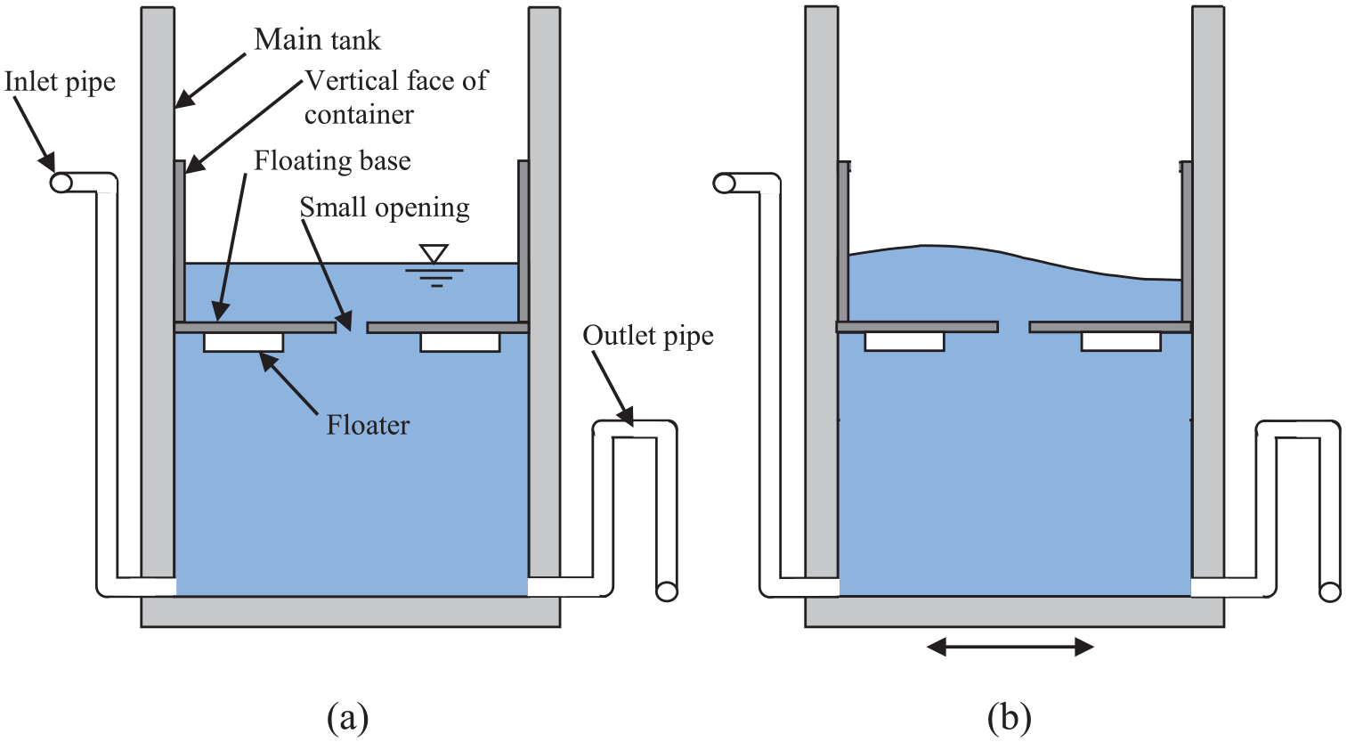
(a) TLD-FB, (b) TLD-FB under lateral vibration.
When the main tank is laterally-excited, vibrational energy is transferred from the main tank to the floating container and from the container to the liquid within it (Figure 1(b)). As a result, sloshing motion is induced in the liquid above the floating base and energy dissipation takes place. Here, both the main tank container and the floating container are considered rigid. During sloshing, the vertical faces of the floating container prevent any rotational motion of the floating base. Thus during lateral vibration, the floating base remains in place and there is no relative motion (rotational or translational) between the floating base and the main tank. This ensures that irrespective of the level of liquid in the main tank, the portion of liquid above the floating base sloshes independently and behaves as an independent TLD with constant liquid depth and frequency.
During practical applications, the inlet pipe should be connected to the main tank near its base as shown in Figure 1(a). It eliminates the possibilities of variation in liquid depth due to the impact of falling liquid on the floating base during filling of the tank. The outlet pipe should have an inverted-U shaped bent before it connects to the main tank to ensure maintenance of a minimum liquid depth in the main tank.
Experimental validation
To validate the effectiveness of the proposed system, a simple experiment is conducted. The experimental set up is shown in Figure 2. A cylindrical plastic container having inner diameter of 12 cm is taken as the main tank. Water is the residing liquid in the tank. A second plastic cylindrical container with external and internal diameter of 11.8 cm and 11.6 cm respectively is taken as the floating container. A hole of 1.2 cm diameter is made at the center of its base. A piece of thermocol is used as a floater and is glued to the underside of the base of the floating container. The total weight of the floating container with floater is adjusted so that the container can float in equilibrium in the water with 1.2 cm of liquid depth above the floating base, providing

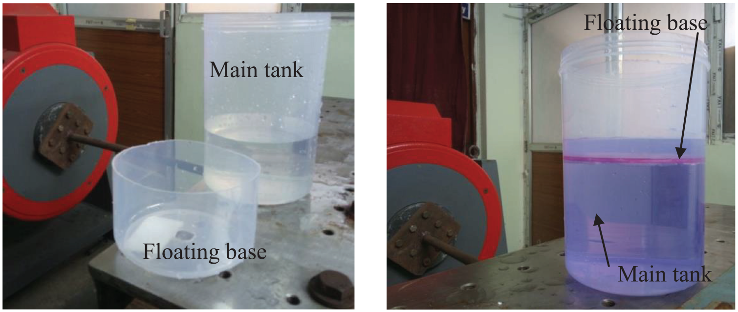
Experimental set-up.
Here, the acceleration due to gravity is denoted by g.
The comparison between the theoretical value of the sloshing frequency with the observed values is presented in Table 1.
Comparison between theoretical and experimental values of sloshing frequency.
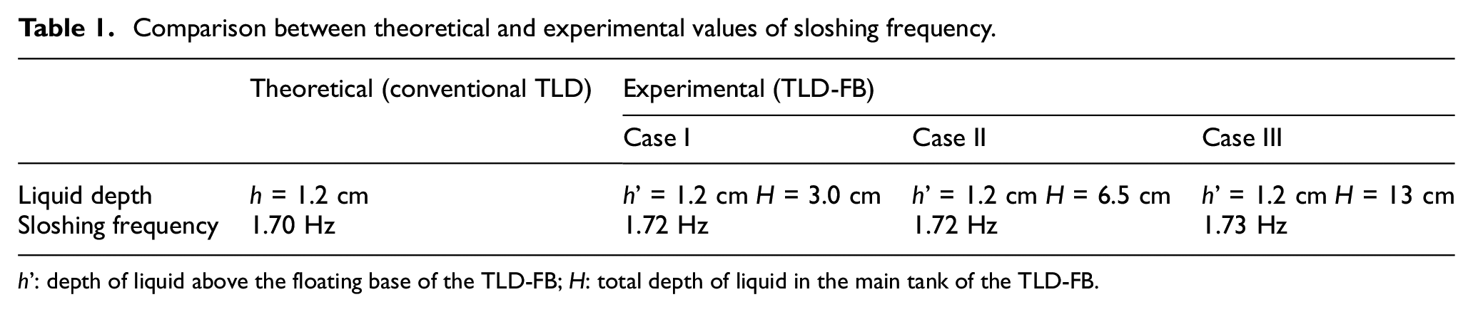
h′: depth of liquid above the floating base of the TLD-FB; H: total depth of liquid in the main tank of the TLD-FB.
From Table 1, it is clear that the sloshing frequency of the TLD-FB is independent of the depth of liquid in the main tank and is very close to that of the conventional TLD with fixed base. Again, during lateral vibration, no relative motion (rotational or translational) between the floating base and the main tank is observed. The hole at the floating base, which is of diameter about one-tenth of the diameter of the container, seems to have negligible impact on the sloshing frequency but is good enough for passage of liquid between the upper and lower portion of the floating base to maintain a constant liquid depth over the floating base when the liquid level in the main tank fluctuates. Snapshots taken at different time interval, t, during free vibration experiment on TLD-FB and conventional TLD having same container diameter (11.6 cm) and
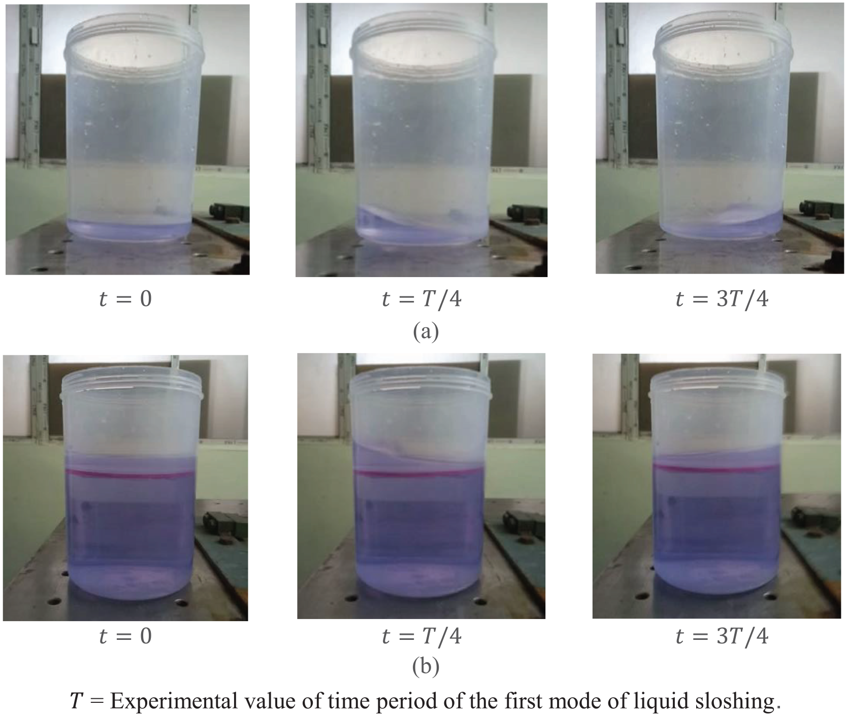
Snapshots taken at different time interval, t, during free vibration experiment on (a) conventional TLD, (b) TLD-FB.
The damping in a TLD occurs due to viscous dissipation in the boundary layers at the bottom and side surfaces of the TLD container, and from free surface contamination. Here, the side and the bottom surfaces of the container for both TLD-FB and conventional TLD are identical, except for the small hole at the floating base of the TLD-FB. The similarity in the free surface profile of the sloshing liquid in the TLD-FB and the conventional TLD, especially the similar rate of decay in the peak of the liquid surface elevation as evinced from Figure 3, signifies that the damping effect in the TLD-FB is akin to that in the conventional TLD.
It is also interesting to note the extent of detuning that would result in the conventional TLD due to the fluctuating liquid depth. Another set of free vibration experiments are conducted on the conventional TLD with liquid depths equal to 3 cm, 6.5 cm and 13 cm, as considered in case of the TLD-FB. While the TLD-FB ensures a constant sloshing frequency of 1.72 Hz corresponding to a liquid depth of 1.2 cm above the floating base, in comparison the observed frequencies of the conventional TLD for 3 cm, 6.5 cm and 13 cm liquid depths are 2.38 Hz, 2.74 Hz and 2.82 Hz respectively, which correspond to 38.4%, 59.3% and 64.0% detuning from the desired tuning frequency of 1.72 Hz.
Design of TLD-FB for an example overhead water tank system
Here, the design of the TLD-FB for the overhead water tank system of an example building is numerically illustrated. The aim is to control the predominant mode of the building structure, having natural period (
Assuming a unit value of the tuning ratio, the required depth of liquid in the floating container is obtained as 0.098 m from equation (1). For 30 numbers of TLD-FB, the effective mass ratio (ratio of mass of liquid in the floating containers to
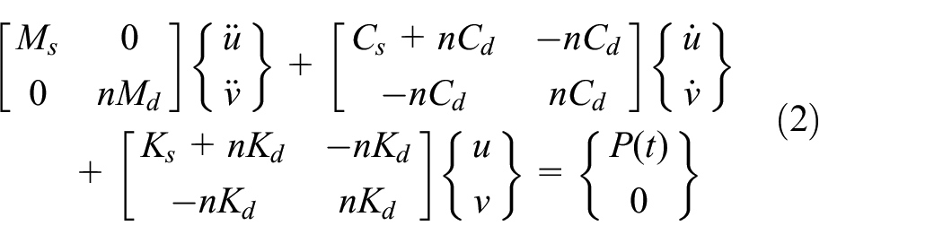
The equations of motion of the equivalent SDOF (single-degree-of-freedom) structure-damper system subjected to load
where,


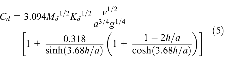
Here,
Equation (2) represents a linear system. At low amplitude excitation, in which the continuity of the free surface of the liquid in the TLD container is maintained, the TLD behavior is almost linear (Ibrahim et al., 2001). With the increase of the excitation amplitude, the TLD response becomes weakly nonlinear. However, here too the linear assumption provides sufficiently accurate results. That is why for practical design of the TLD, the linear model is widely adopted (Lotfollahi-Yaghin et al., 2016; Nguyen et al., 2018; Tait, 2008; Zahrai et al., 2012). When the excitation amplitude become high, wave breaking takes place and for even higher amplitudes the sloshing liquid can slam on the tank wall with impact. This type of TLD response necessitates nonlinear modelling (Ibrahim et al., 2001). In the present study, it is assumed that the linear model of the TLD can be used for design of the TLD-FB.
Now, it is assumed that the mass of the tank containers and the non-sloshing mass of the water in the tanks are lumped with the mass of the structure. The variation in mass of the structure due to fluctuation in liquid level in the tanks is neglected as the total weight of water in tank full condition is very low as compared to the structural weight. The value of
Let the example structure be subjected to a synthetically generated, close to white noise, broad-banded base acceleration input with peak acceleration value of 0.40 g, and 300 s duration, as shown in Figure 4. The time history of displacement response of the structure, with and without TLD-FBs, for the considered excitation is presented in Figure 5, which shows 25.8% and 31.7% reduction in rms (root-mean-square) displacement and peak displacement respectively. The response reductions achieved by the proposed TLD-FB is thus significant for a passive damper system. In comparison, the displacement response of the structure is hardly mitigated by the presence of the tank acting as a conventional TLD without FB. As the water level in the tank continually fluctuates from functional requirements, a sample result for the structural displacement with the tank in half-full condition is presented in Figure 5. The reductions in rms and in peak displacement of the structure for this case are evaluated as 7.0% and 5.2% respectively.
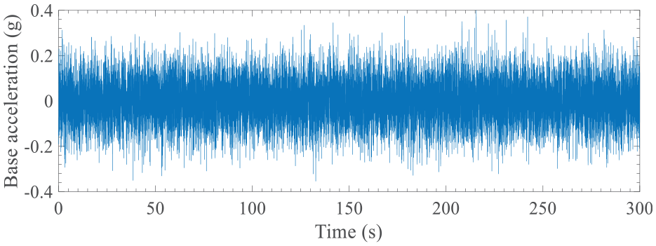
Input white noise base acceleration.
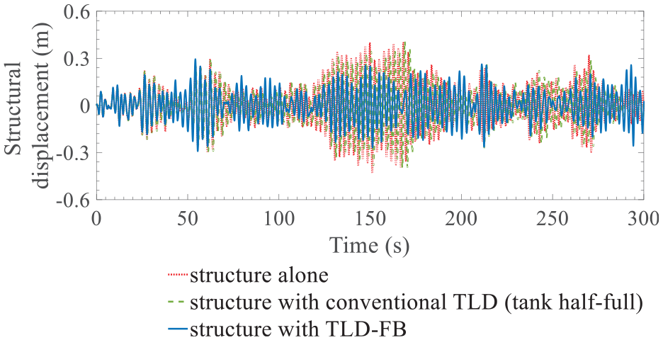
Displacement time history of equivalent SDOF structure (i) structure alone, (ii) structure with conventional TLD (tank half-full) and (iii) structure with TLD-FB.
Further, power spectral density analysis of the displacement response of the structure alone, structure with conventional TLD (tank half-full) and structure with TLD-FB is carried out and the results are presented in Figure 6. It is clear that the vibrational energy of the structural response is reduced significantly by the TLD-FB and this highlights the effectiveness of the TLD-FB. As expected, the reduction in vibrational energy by the conventional TLD in the form of the tank in half-full conditions is much less as compared to that by the TLD-FB.
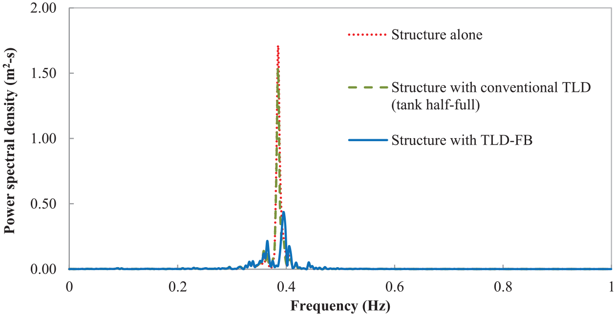
Power spectral density of structural displacement (i) structure alone, (ii) structure with conventional TLD (tank half-full) and (iii) structure with TLD-FB.
Conclusion
Liquid storage tanks are not generally considered for design as TLD as they are deep tanks with very little inherent energy dissipation property. Again, with the fluctuation in liquid level in those tanks due to functional requirements, the frequency of liquid sloshing motion varies, which results in detuning of the damper. Through the proposed design in this paper, a movable horizontal partition is created in the liquid storage tank by inserting a floating container into the main tank. A hole at the base of the floating container ensures maintenance of required water level above the floating base while the liquid level in the tank fluctuates due to functional requirements. The wall of the floating container prevents any relative motion between the floating base and the main tank during lateral vibration. With these improvisations, a liquid storage tank is converted into TLD-FB with minimal interference with the function of the main tank, except for the requirement of minimum liquid storage, which is also small compared to the total capacity of the main tank. The experimental study shows that the behavior of TLD-FB is similar to the conventional TLD and does not get affected by fluctuation in liquid level in the main liquid container. The numerical study highlights that a feasible and practical configuration of TLD-FB is achievable and the reduction attained in the maximum value of the amplitude of displacement response of the example structure is significant for a passive vibration control device. Hence, using the proposed technique, the existing liquid storage tanks can be converted easily into effective and predictable vibration control devices. The performance of the TLD-FB can be further increased by installing flow damping devices, such as slat screens, baffles, etc., in the floating container of the TLD-FB.
Footnotes
Declaration of conflicting interests
The author(s) declared no potential conflicts of interest with respect to the research, authorship, and/or publication of this article.
Funding
The author(s) received no financial support for the research, authorship, and/or publication of this article.
