
Abstract
To improve the safety and security of the structures with irregular plan configuration, the new torsionally effective passive control system (ICS) was first proposed by the author, which utilizes a new design configuration to dissipate the unwanted energy from the structures in the lateral and torsional directions. In this research, a new active structural control approach, which is the active form of the ICS (or active integrated control system, AICS), is introduced as an alternative active control system, especially for the buildings with torsional sensitivity. In the design of active system configurations, two actuators driven by the linear quadratic regulator (LQR) are implemented and used to apply the optimum control forces to the ATMDs and AICS. For examining the performance of the proposed system configuration, the final design is applied to the 9-story Benchmark steel structure subjected to bidirectional three historical earthquakes. The obtained results show the overall performance of structural performance by using the AICS is substantially improved as compared to conventional ones (ATMDs) under selected ground accelerations with a 3% to 6% improvement in the lateral directions and by nearly 20% in the torsional direction in terms of the peak and root mean square response reduction.
Keywords
Introduction
Structures with considerable eccentricity in plan layout may lead to significant aerodynamic torsion loads causing the torsional modes to become more dominant, see Figure 1. This sensitivity leads to excessive increase not only in lateral motions but also in torsional motion under dynamic loading. Damage investigations in the few past earthquakes have often emerged that torsionally irregular buildings (TIBs) underwent more intensive damage because of extreme torsional responses and unevenly distributed stress than related regular structures (Raheem et al., 2018). This torsional sensitivity introduces the significant challenges in the seismic analysis for TIBs. Therefore, many innovative passive and active smart control systems have been proposed and successfully applied in the real-life implementation by the engineering community to keep the structures safe from structural damages.
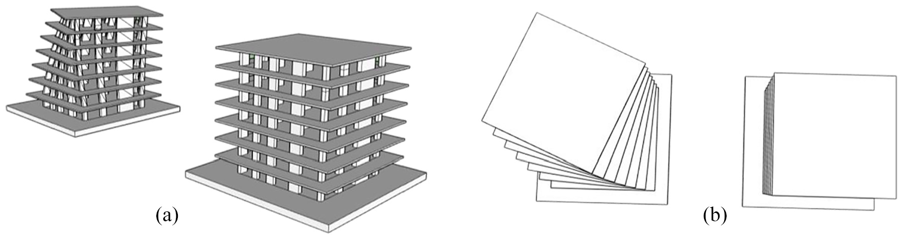
Illustration of torsional mode and torsional in 3-D civil structures: (a) elevation view, (b) bird’s eye view.
Tuned Mass Damper (TMD) is one of the widely used passive control systems that is employing appropriate mass, damping, and stiffness to the main structure. However, its effectiveness is highly sensitive to the tuning parameters and only useful at the small frequency range. If it is not well-tuned, it may even increase the unwanted dynamic response on the system (Shen et al., 2011). Therefore, many researchers have studied this subject, and they come up with solutions for obtaining the properties of TMD. One of the methods to get the tuning parameters is the tuning (design) equations, which are likely to be used by many engineers (Abubakar and Farid 2009; Sadek et al., 1997; Salvi and Rizzi, 2015). Besides the design equations, meta-heuristic (optimization or genetic algorithm) methods have been getting so much attention these days to get these dynamic properties (Arfiadi and Hadi, 2011; Özsar and Bozer, 2015; Pourzeynali et al., 2013; Singleton et al., 2020). In addition to obtaining these properties by equation or optimization methods, the placement of TMD or Multi-TMDs plays an essential role in using them as effectively as possible. Using more than one TMD and placing them effectively on the structure can provide to control multi-mode control; therefore, they become more efficient at a wide range of frequency spectrum (Elias et al., 2019; Gill et al., 2017; Radmard Rahmani and Könke, 2019).
Although a passive control system is widely and intensively used in the structural control, this system is not a comprehensive method to follow because of its limitations, such as not being adaptable to structural changes and not useful in a wide range of frequency and loading conditions (Dicleli and Mehta, 2007). If the system becomes active by adding one or more actuator that provides external power, the system gets more effective and resistant to strong ground motions. However, it is not always operative to have tremendous asctuator energy into the civil structure. Even if possible, it has the potential to destabilize the structure, unlike a passive control system. Therefore, it is necessary to control the actuator by control methodology that can provide the optimum force for the desired design perspective. The used control methodology in this study is a Linear Quadratic Regulator (LQR). In addition to that, self-powering and energy-harvesting for active control systems are currently becoming more attractive to overcome such disadvantages (Cai and Zhu, 2019; Cai et al., 2020; Zuo and Cui, 2013).
Engineers and researchers have successfully integrated all these methodologies into the control systems employed in civil structures (Soong, 1988). The linear quadratic regulator (LQR) controller has been extensively used by many researchers such as Chang and Soong (1980), Guclu and Yazici (2008), Jiang et al. (2010), and Kim et al. (2013). A Linear Quadratic Gaussian (H2/LQG) controller has been implemented to a structure equipped with active devices (Asai, 2014; Bitaraf, 2011; Dyke and Spencer, 1996; Ohtori et al., 2004). A Hinf controller has been used to deal with mass and stiffness uncertainties to decrease the response of a building with an active mass damper (AMD) by Huo et al. (2008) and Bitaraf (2011) has studied the effectiveness of compensation algorithms for an AMD. Dyke and Spencer (1996), have examined an AMD analytically and experimentally by using acceleration feedback control to suppress the response of slender tall buildings.
Most of the passive control systems can become as active systems by adding an actuator to the system and controlling the actuators with a set of control algorithms. Active Tuned Mass Damper (ATMD) is first introduced into the literature in 1992. The performance results of ATMD are compared with a passive TMD. The comparison showed that active-controlled TMDs are much more effective by getting 40% to 50% or more response reduction. Since then, many researchers continue to study active control systems with different control algorithms like fuzzy logic, LQR, and LQG controllers (Cao and Li, 2004; Samali and Al-Dawod, 2003). Abe (1998) have proposed an Active Tuned Liquid Damper (ATLD) with magnetic fluid as an alternative active control system. Its performance is verified experimentally by applying it to a two-story model building. The results show that it gives a higher vibration reduction and is less sensitive to the detuning effects. Active tendon control (ATC) was studied by Reinhorn et al. (1989) and Nigdeli and Boduroglu (2013). In addition to academic works published as simulational and experimental works, some real-life implementations of these active control systems successfully applied to the structures are provided here to show these systems effectively used by design engineers (Sakamoto et al., 1994). Some examples with the application of active control systems can be given as the Sendagaya INTES Building (1992), the Kyobashi Seiwa building (1994); the Shanghai World Financial Center Tower (1997); and the HERBIS Osaka Building (1997).
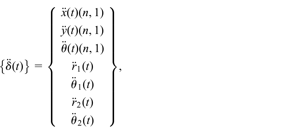
One of the intensively and commonly used active energy absorbers is the active tuned mass dampers (ATMDs), which are recognized by structural engineers to substantially reduce the seismic response when the structure is exposed to seismic loads. However, they may not always be a comprehensive way of reducing structural responses, particularly for high-rise buildings with plan irregularity. Due to those irregularities during a strong earthquake, the building can be exposed to a significant amount of excessive torsion caused by lateral vibrations. Therefore, in this study, the Active Integrated Control System (AICS) configuration, which is for effectively surpassing both lateral and torsional vibrations, is introduced. To test the effectiveness of the AICS, the ICS is strengthened by two actuators placed to each of the lateral directions; however, they can move in either lateral or torsional directions with the help of the bearing systems (tires). For the ATMDs system, two actuators are only fixed to each lateral direction that they are not capable of dissipating undesirable vibration in torsional direction. For both control systems (ATMDs and AICS), the optimal forces are produced by the actuators, which are controlled by LQR controllers. For performance evaluation of the AICS, it is applied to the Benchmark 9-story steel building under selected bidirectional earthquake ground motions and compared its performance to the conventional ATMDs.
Active integrated control system
It is a well-established fact that a conventional TMD is effective only in the direction that it is used and useful only for a small range of frequency that can be operative in a modal frequency tuned. Therefore, it has only a little or no effect in controlling the torsional response from this angle of design perspective. For diminishing this limitation, the ICS was proposed as an effective control system in both the torsional and lateral directions in the study by Akyürek, Suksawang, and Hiong (2019).
It includes two TMDs placed along with two orthogonal directions at the roof floor of the structure. It utilizes suitable linear springs & dampers and additional masses to make sure that the TMDs in the composition of the ICS will disperse unwanted energy suitably. Moreover, one side of TMDs in each orthogonal direction in the ICS composition is attached to the torsional damper located in the center of mass, other restricted by torsional springs fixed to the wall on the top floor. Each mass in the ICS design can be used by the TMDs as well as by the lateral pendulum system with the aid of the global bearing systems and rigid rods assuming its mass is neglected. They will, therefore, be operative in both orthogonal and torsional directions, thanks to the composite structure of the ICS shown in Figure 2.
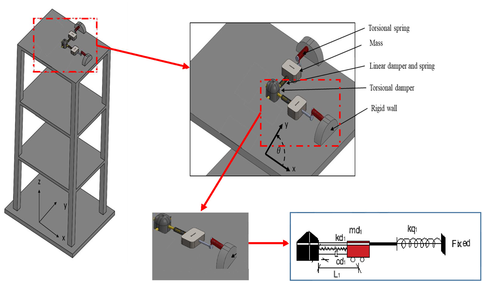
A representation of a three-story civil structure with the ICS.
The composition of the passive ICS illustrated above is strengthened by the same dynamic properties of the actuators with ATMDs stated above. While these actuators can move by the help of the global bearing system, which allows the linear actuator to control torsional motion in this design of AICS, they are only effective in the direction placed and tuned in the ATMDs, namely, not useful for controlling in torsional motion. Schematic configurations of the ATMDs and AICS are illustrated respectively in Figure 3(a) and (b).

Schematic configurations of: (a) the orthogonal ATMDs and (b) the AICS.
Structural dynamics and mathematical modeling
For an eccentric building, the primary first modes of vibration may still dominate the response; however, higher-order modes of vibration may additionally take place during an earthquake as well. Especially for a bidirectional earthquake excitation, it is expected that higher-order mode shapes can dominate the torsional motion of the structure. Therefore, for such eccentric buildings, it is essential to consider the effect of bidirectional earthquake ground motion and the properties of traditional TMD, which are the influence of dimension, the best location, and so forth in evaluating the performance of the control system. It is assumed that the mass of the TMDs can move forth and back from the center of mass of the top floor through orthogonal direction placed because the influence of the TMDs’ location is not considered. In addition the assumption above, the center of mass is located at the center of each level. Then, the equation of motion for the eccentric buildings actively controlled is mathematically stated as follow:

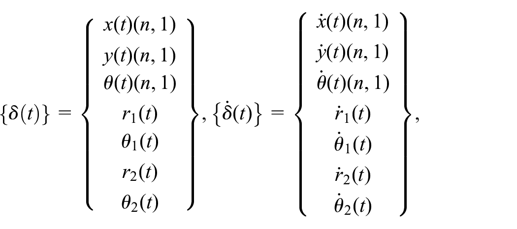

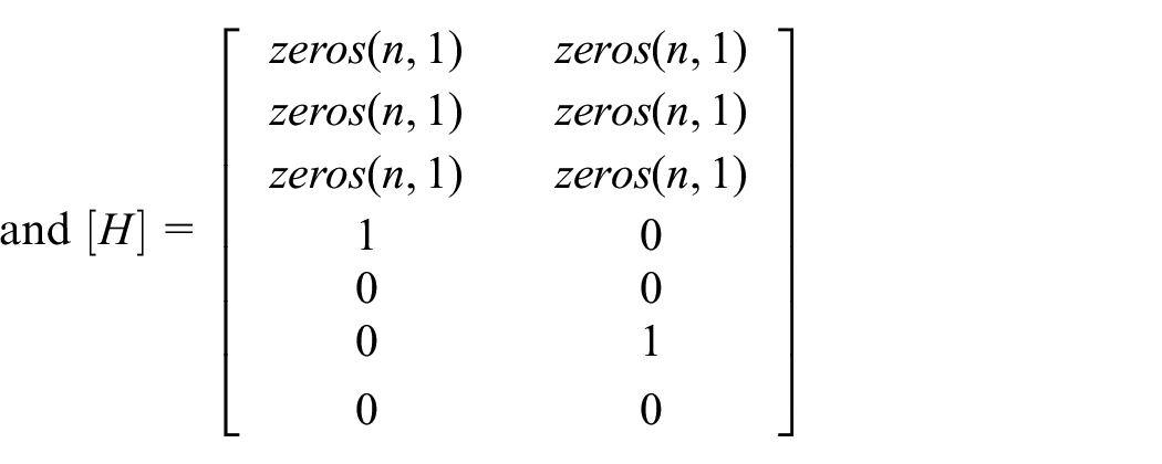
Where,


Where Z(t) is the state vector and A, B, Cr, and Dr are, in order, the system matrix, input matrix, output matrix and the direct transmission matrix with appropriate size. The desired output, in this study, is the top floor displacements in three directions.
Control system design
Optimum dynamic design
Mass & damping ratios and tuning frequency are vital optimum parameters to increase the effecctiveness of a conventional TMD. For this study, the mass ratio is assigned in both horizontal directions as
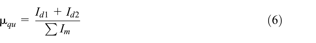


Where
The fundamental and optimum dynamic properties of the ATMDs and the AICS.
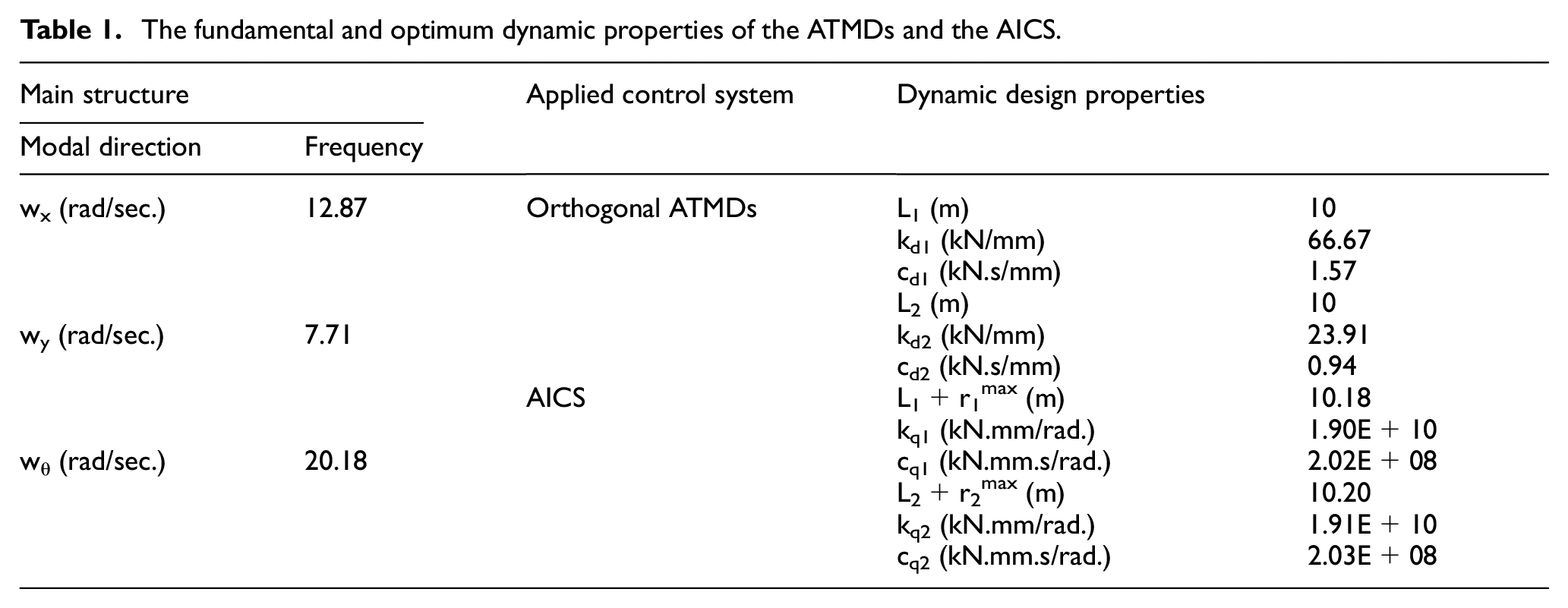
Dominant-modes in all three directions is obtained by employing the eigenvalue problem. These are the parameters; mass ratio (μ1, μ2), initial length (L1, L2), damping ratio (ξd1, ξd2), stiffness constants (kd1, kd2), damping constants (cd1, cd2) for applied the ATMDs from the center of mass (CM) through x- and y-directions. L1+r1max and L2+r2max are defined as the maximum length that torsional pendulum in the AICS that they can reach during a selected dynamic earthquake input. It is the sum of the initial length and the maximum response of corresponding ATMDs. Torsional spring constants (kq1, kq2) and damping constants (cq1, cq2) are the dynamic parameters of the first and second ATMDs connected in the form of the AICS.
Optimum controller design
In addition to a passive control system such as TMDs and ICS, an active control system like ATMD and AICS have the ability to change itself throughout earthquake loading. Even if it is such an adaptive control approach, there are still some crucial disadvantages using it, for instance, measurement errors, time delays, phase lag effects, and so forth, especially when in the hands-on experimental work for verification purposes. In the simulation of seismic analysis of this study, the impact of such disadvantages is neglected for simplification (Akyürek et al., 2019). It is also assumed that the outage of electricity and inelastic deformation effects of the structural components on the control systems performances are neglected in the seismic analysis. In the active control design, the primary aim is to obtain a control vector that decreases a cost function depending on the structural constraints and dynamics. The cost function can be mathematically expressed as
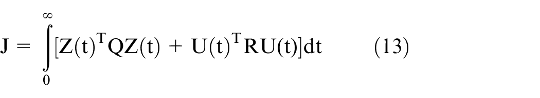


where Q and R are respectively state and control weighting matrices that should be semi-positive definite as well as positive definite. There is a solution exists and unique if (A, B) and (A, N) are, in order, stabilizable and detectable.

Q and R matrices have the relationship between the control forces required and the response reduction. In this paper, the roof floor displacements of the structure in the orthogonal directions (


where Q and R are found by trial and error method and taken 9.104 and 10−12 in the analysis, then, the closed-loop form of an active control system turns out by substituting equation (19) into equation (2) as:

Now, the controller design is ready to control the actuator.
Significant attention so far has been paid on a single or multi-actuators implementation in the active control system which is applied either on the top or any number of floors of a structure. It is not always possible when actuator installation at every story is considered. Because it, in practice, is costly and not easy to set up a vast number of electric and mechanical components of the actuators. Fewer actuators implementations on the system would be more applicable in terms of cost and simplicity. In this study, there are two actuators in the design of the ATMDs and AICS, assumed that they are identical and could provide desired force need in both orthogonal directions, as seen in Figure 4(a) and (b). The LQR controller is employed to control actuators, so the ATMDs and AICS can more effectively suppress the seismic vibration from the main structure.
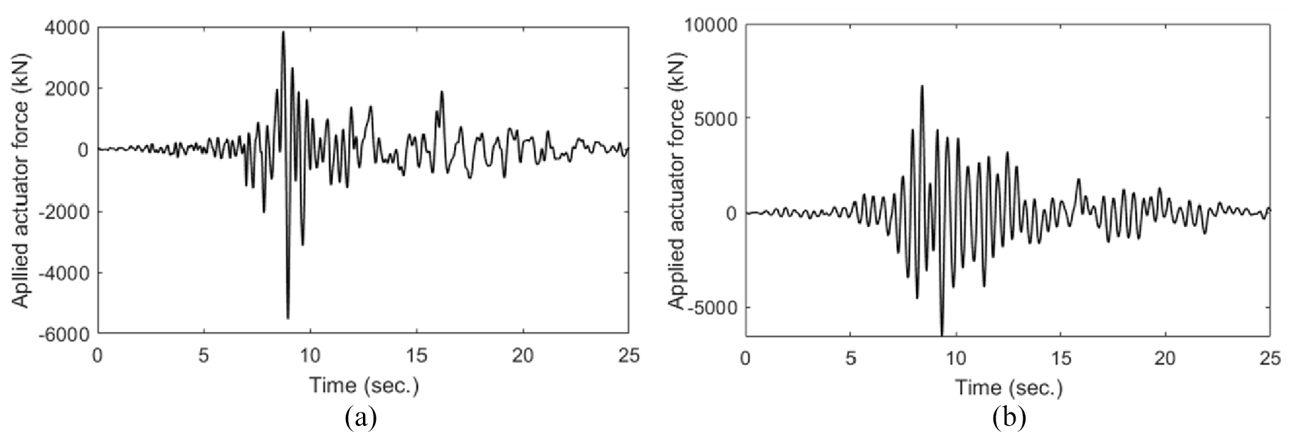
Applied force (kN) to the main structure by orthogonal actuators in the ATMDs and AICS: (a) in the x-direction and(b) y-direction.
Model overview and performance criteria
Model building overview
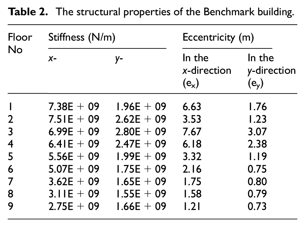
Benchmark 9-story steel building was determined as a reference structure to apply the proposed control system. It has the wide-flange columns made of 345 MPa steel and simply linked to the ground. In the plan layout of the Benchmark building, the orientation of the column’s placement is illustrated in Figure 5(a) and type of frames’ connections (Moment Frames (MFs) and Simple Frames (SFs)) are illustrated, as seen in Figure 5(b). It also has the bays 9.15 m long by five bays in the x-direction and six bays y-direction. The interiors bays have simply connected to the composite floor at each level that they are made of 248 MPa steel. It is assumed that all stories of the structures function as rigid diaphragms. The seismic mass for the ground level; the first level; for the first level; from the second to eighth levels; and the ninth level are respectively 9.65×10⁵ kg; 1.01×10⁶ kg; 9.89×10⁵ kg; and 1.07×10⁶ kg. The total mass of the entire structure above-ground level is 9.00×10⁶ kg. The dynamic and geometric parameters for each level of the building are taken into account as seen in Table 2. For further structural design information, the readers can look up to Federal Emergency Management Agency (FEMA) (2000) and Ohtori et al. (2004).

The Benchmark 9-story steel building: (a) column placements, (b) beam connection types.
The structural properties of the Benchmark building.
Performance indexes and ground motion selections
The performance of control systems rests on the characteristic of the input earthquake motion, so there are three loading cases considered and picked to understand the impact of the earthquake characteristics on the AICS. These selected excitations cover all possibility of an earthquake once it occurs, namely N-S dominant, E-W dominant, or both. They are respectively bidirectional components of the real earthquake excitations of El Centro in 1940; Loma Prieta in 1989; and Kocaeli earthquake in 1999, see in order Figure 6(a) to (c).
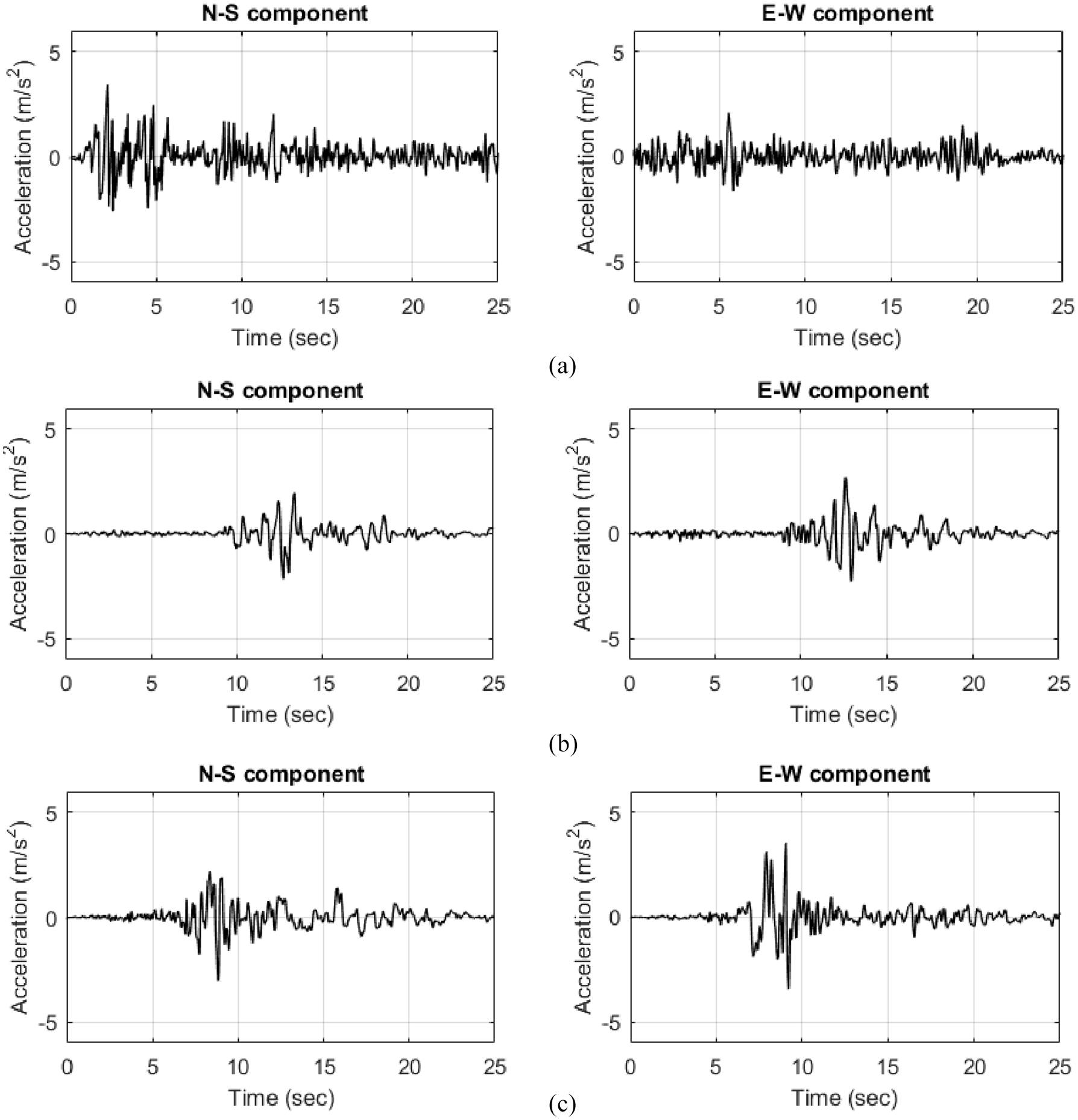
Three historical earthquakes: (a) El Centro, (b) Loma Prieta, (c) Kocaeli earthquake.
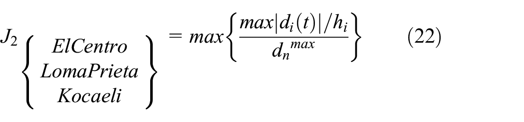
There are many performance criteria (PC) stated in their study by Ohtori et al. (2004), but the first three of them; the maximum floor displacement (J1), the maximum drift (J2), and floor acceleration (J3) are considered to evaluate the proposed control systems, and they are respectively given by;


Where
Simulation results and discussion
The Benchmark building was picked for a numerical example, and all the dynamic analyzes were performed in Matlab and Simulink, which are mutually synchronized programs. The structures retrofitted respectively by the two ATMDs in both orthogonal directions and AICS, as seen in Figure 3(a) and (b). For examining the performance impact of the new design configuration under the bidirectional loading cases, the same physical actuators with the same dynamic characteristics were used for both the ATMDs and AICS systems. The two actuators were fixed at the base of the top floor in the design of the ATMDs; however, they might move laterally and torsionally by global bearing systems (tires) for the design of the AICS. The outcomes of the Benchmark building with the ATMDs and the AICS were obtained and compared with each other. Flown chart for structural design and analysis with the ATMDs and AICS under bidirectional earthquake loading is given in Figure 7.
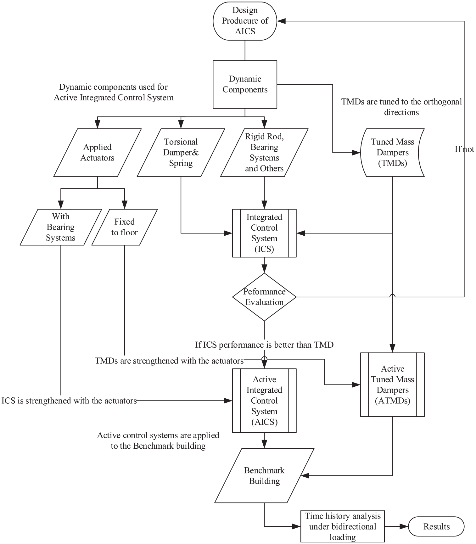
Flown chart for structural design and analysis with the ATMDs and AICS.
Total frequency responses of the structures with/without a selected active control system were obtained, which are independent of the earthquake input characteristics. First x-translational and x additional -due to coupling effects- frequency responses were collected and superposed. For y-direction, the same procedures were applied, and the total y-frequency response was acquired. In the end, the full x- and y-frequency responses, including coupling effects due to eccentricity, were superposed, and it was finally achieved to draw the whole frequency plot, as shown in Figure 8.
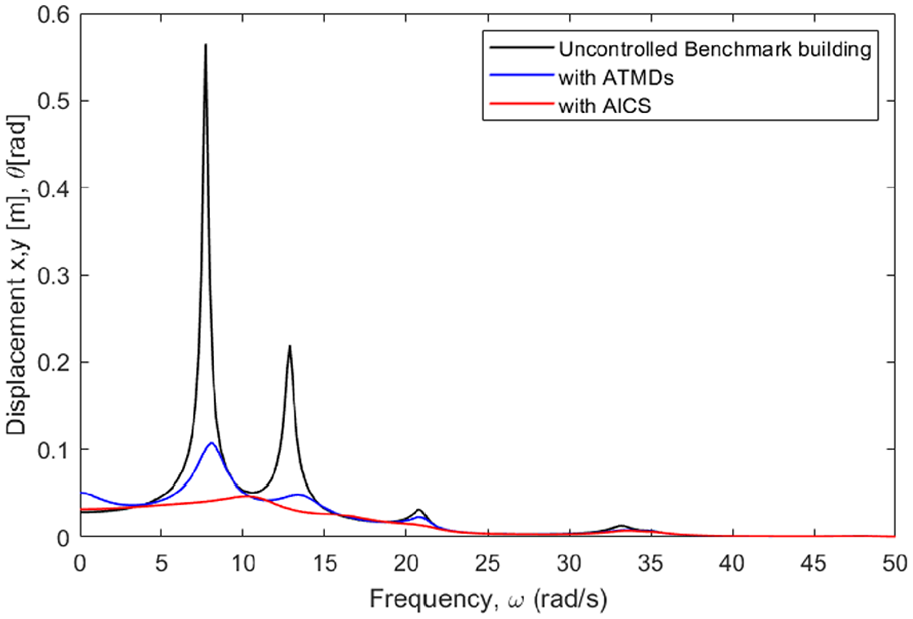
Bode plot for the roof floor displacement of the Benchmark building.
The peaks in the plot represent the first x- and y-translation and torsional modes. It is observed that the maximum peak amplitude in the first mode -which mostly dominates total response- belongs to the bare Benchmark buildings, which are about 0.58 m. In addition to this, ATMDs can effectively surpass the amplitude of the structure to roughly 0.22 m, while AICS are the best to minimize the frequency response by 0.05 m.
Here, there are two translational actuators applied to the new design configuration of the proposed control system. The actuators provide translation external energy into two directions for the active tuned mass dampers (ATMDs). At the same time, they can generate power in the translational and torsional direction with the help of global bearing systems for the active integrated control system (AICS). The analysis is made, and the peak and RMS responses of the ATMDs and AICS are obtained and tabulated in Table 3.
The responses of the structure and its application with ATMDs and AICS.
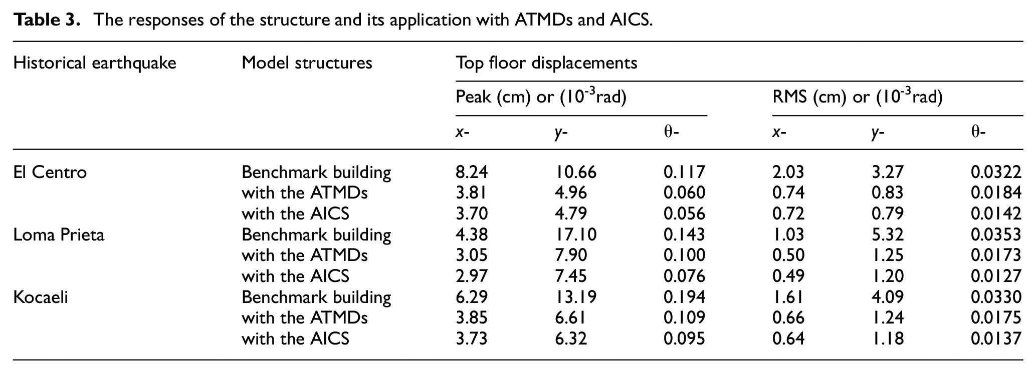
It is tabulated in Table 3 that the peak and the RMS results for the bare structure and the structure with the control systems are acquired. As expected that the uncontrolled Benchmark building undergoes the highest amplitude for all directions at the roof floor once exposed to bidirectional El Centro, Loma Prieta in the tuning directions, and Kocaeli ground motions in the detuning direction. In general, the active control strategy significantly improves system response reduction capacity. In addition to this, it increases the safety and stability of the structure by eliminating detuning effects caused by the earthquake input characteristics, in which the passive control strategies are inactive. Therefore, the active control strategy can significantly improve the structural performance; however, it also has some disadvantageous, for instance; it may need a vast amount of external energy and additional control stuff like sensors, computers so forth. Overall, the performance of the AICS is significantly improved by comparing to the ATMDs performance in terms of response reductions in three directions.
Figure 9 shows that the performance comparison of the active control systems, ATMDs, and AICS, is assessed in terms of peak and RMS response reduction percentage in three directions. By employing a new active control system (AICS) with the same actuators/dynamics and control characteristics, there are substantial improvements in the response reduction as compared to the ATMDs. For the peak and RMS response reduction, there is an approximately 3% increase in the x-direction and about a 6% increase in the y-direction. It is also noteworthy that there is a significant improvement of nearly 20% for the torsional direction. In all three directions, the performance of the AICS outcomes to the performance of the ATMDs.
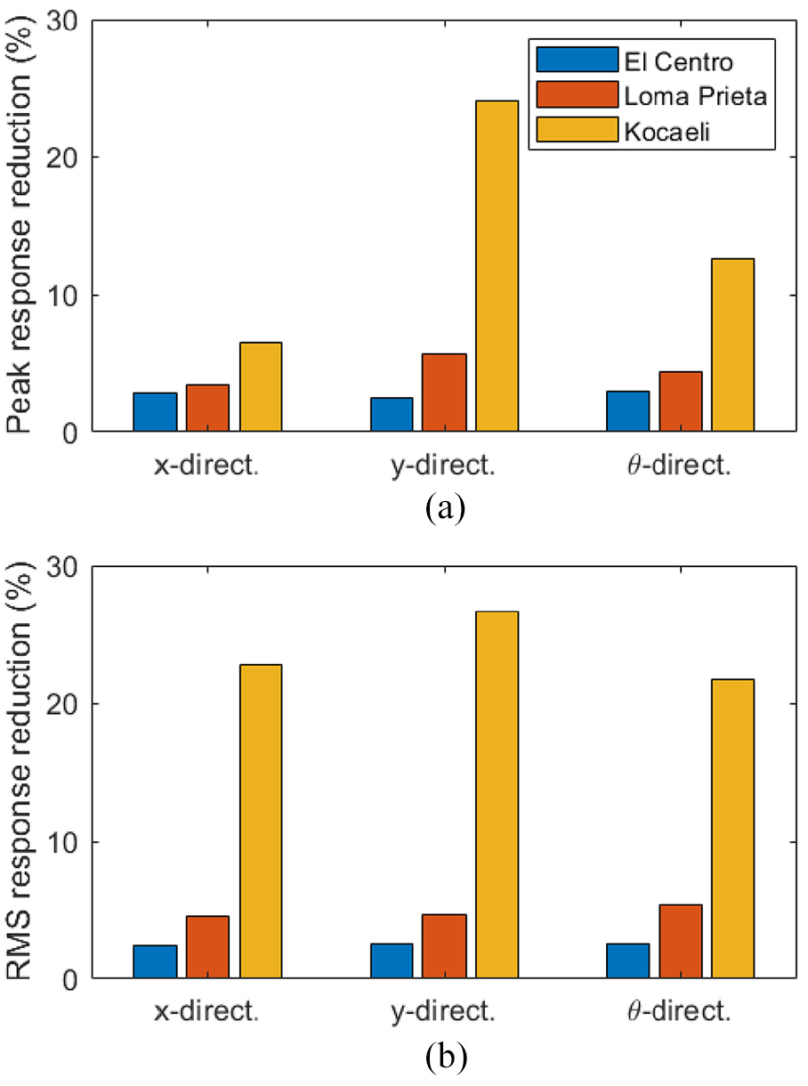
The percentage of the AICS response reduction by comparing to ATMDs: (a) for the peak, (b) and the RMS responses.
When an earthquake excites a building, it can be x-dominant excitation or y-dominant excitation or both. It is a well-known fact that the effectiveness of TMDs in the design of the ATMDs and AICS depends on the earthquake characteristic. Thus, TMDs were tuned respectively placed in the x- and y-directions, which they were, in order, controlled by 2nd mode and 1st mode of the structure, and their design configurations were kept the same for any loading cases. This design assumption can cause detuning effects for the control systems in the case of Loma Prieta and Kocaeli earthquakes.
It is a convenient parameter (inter-story drift ratio) on how to test structural performance, especially for those having plan irregularity in high-rise buildings where torsion becomes an ongoing issue. In the orthogonal directions under three historical earthquake excitations, the drift ratios are restricted sufficiently overall structures by retrofitting the building with the ATMDs and AICS. It is noteworthy that integrating the AICS into the Benchmark building keeps the inter-story drift ratios in the safest range in the orthogonal directions, not only for tuning see Figure 10(a), but also detuning cases see Figure 10(b) and (c) as compared to the ATMDs.
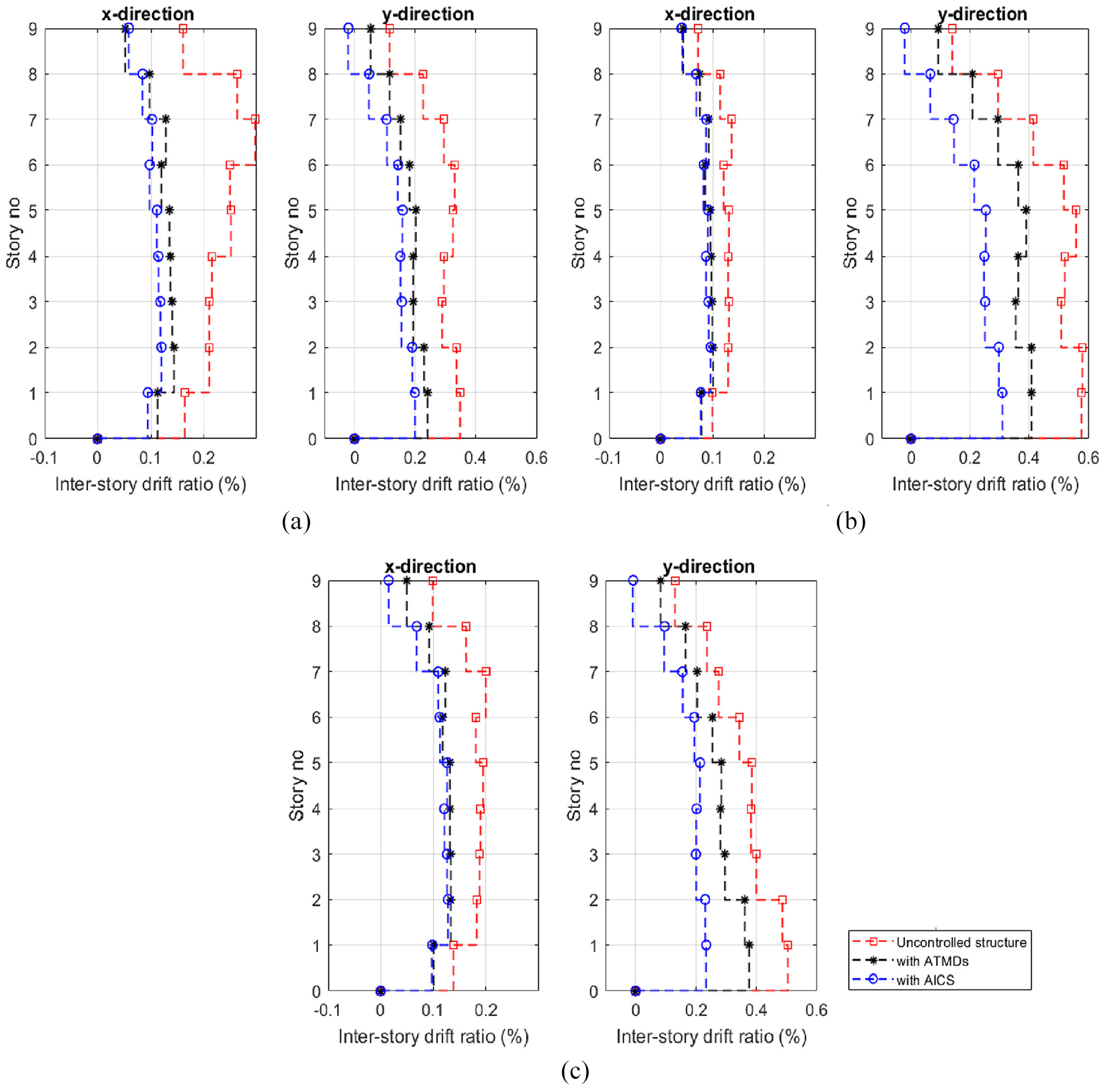
The model structures’ inter-story drift ratio when excited by: (a) El Centro, (b) Loma Prieta, (c) Kocaeli earthquake.
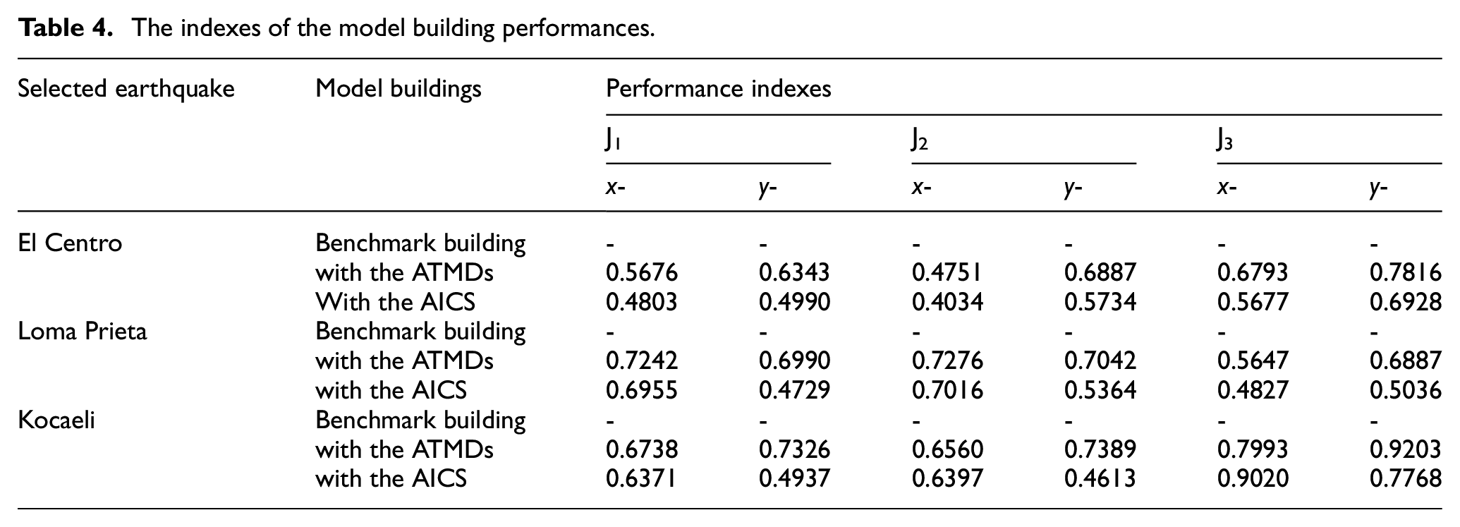
The notations (J1, J2, and J3) given in Table 4 represent the peak displacement, the inter-story drift ratio, and the peak acceleration. For both tuning and detuning cases, (J1–J3) values are overall less than one, and AICS’ values for most of the circumstances show a better performance, except that the peak acceleration in the x-direction under Kocaeli earthquake is slightly bigger than the ATMDs. AICS’ performance values are less than the ATMDs, which indicates the effectiveness of the AICS, expect the fact that peak acceleration in the x-direction under the Kocaeli earthquake (0.9020) is higher than the ATMDs (0.7993). This increase might happen because the detuning effects due to the Kocaeli earthquake lead to a rise in the x-lateral acceleration; however, in the y-direction, it successfully reduces the undesirable vibration from the structure. Another reason is the rise of the x- acceleration is the eccentricity that plays a more critical role in the x-direction; therefore, the W-E dominant earthquake-like Kocaeli earthquake can increase the torsional coupling effects on the structures. The coupling effects, thus, might lead to an increase in the acceleration in the x-direction, and the AICS cannot successfully handle torsional acceleration in the x-direction. Under all tuning and even in detuning circumstances, overall, the AICS exhibits quite improvements in the structural performance by comparing to the conventional ATMDs placed in the orthogonal directions.
The indexes of the model building performances.
Conclusion
Active Integrated Control System (AICS) is presented here in designing the new configuration of the active control system for those buildings having irregularity eccentrically in plan and elevation. Two actuators, which are driven by the LQR controller, are assigned to generate the desired control forces for the ATMDs and AICS system in both horizontal directions. The performance of control systems depends upon the applied earthquake input characteristics. When an earthquake strikes a building with an angle of attack, there are three possibilities, namely N-S dominant, E-W dominant, or both that buildings can experience. Therefore, the selected earthquake covers all possibilities of an earthquake once it occurs. The control systems are evaluated under these selected bidirectional historical earthquake motions respectively El Centro in 1940; Loma Prieta in 1989; and Kocaeli earthquake in 1999. This paper mainly aims to assess the performance evaluation of the AICS when exposed to different bidirectional earthquake excitations that may result in either tuning or detuning effects. Moreover, two orthogonal traditional Active Tuned Mass Dampers (ATMDs) is integrated into the Benchmark building for comparison purposes in validating the effectiveness of the AICS. These conclusions would be figured out as follow:
It is observed from the frequency response that, as expected, the bare Benchmark building has the maximum peak amplitude (nearly 0.58 m) in the first mode that mostly dominates total response. In addition to this fact, ATMDs can effectively surpass the amplitude of the structure to roughly 0.22 m, while AICS are the best to minimize the frequency response by 0.05 m.
Employing the AICS has improved in limiting the inter-story drift ratio. It also adequately reduces the RMS and peak displacement of the Benchmark building on the top floor. Therefore, the AICS performs superior to the orthogonal ATMDs in terms of response reductions.
In the assessment of the performance evaluations, there is a significant improvement obtained for both the tuning and the detuning cases by utilizing both dynamic control techniques. The (J1-J3) values are in general less than one, and AICS has the best performance in general, except that the small increase in the x-direction (0.9020) under the Kocaeli earthquake is higher than the ATMDs (0.7993). This extension may happen due to the detuning impacts because of the Kocaeli earthquake or the coupling response due to the eccentricity; however, it effectively lessens the vibration from the structure in the y-direction. Under all tuning and even in detuning conditions, the AICS, in general, shows relatively better performance by comparing with the ordinary orthogonal ATMDs.
Footnotes
Declaration of Conflicting Interests
The author(s) declared no potential conflicts of interest with respect to the research, authorship and/or publication of this article.
Funding
The author(s) received no financial support for the research, authorship and/or publication of this article.