
Abstract
This paper proposed an Offset Multi-Wedges Swaged Couplers (OMWSC) as mechanical connection of steel rebars. The behavior of the connection consisting of two steel rebars connected by one OMWSC under uniaxial tension is investigated by Finite Element Model (FEM) simulations, which is verified through test results by considering the load-displacement curve, the failure mode and the failure deformation, and the insertion force to install the wedges. Parameter studies are carried out using the verified FEM. Studied parameters included the rebar surface type, the wedge diameter, the steel rebar diameter, the overlap ratio of the wedges that is defined as the ratio of wedge distance to the effective wedge distance, the extrusion ratio that is defined as a half of the wedge diameter to the gap of the two rebars, and the edge distance. Design equations for the coupler and the wedge of an OMWSC are proposed. Verification of the proposed design methods proved the OMWSC designed using the proposed method would not fail prior to the failure of steel bars.
Keywords
Introduction
Precast concrete structures have remarkable advantages, such as quick construction, lower energy consumption, and better components quality (Breccolotti et al., 2016; Spremic et al., 2017; Tazarv and Saiidi, 2016; Yan et al., 2018). Steel rebars between precast concrete structural components usually are connected using Grouted Sleeve Couplers (GSC) in China. However, the GSC require strictly position and longitudinal error tolerance for the steel bars, which are very difficult to acquire in precast concrete structure components (Ameli et al., 2015; Kuang and Zheng, 2018; Rahman et al., 2015; Seo et al., 2016). At present, there is still no effective way to control and inspect the construction quality of GSC (Ling et al., 2012).
Mechanical couplers for steel rebar are adopted ever-increasing in precast concrete structures (Milosavljevic et al., 2018), such as the Parallel Threaded Coupler (PTC), the Tapered Threaded Coupler (TTC), the SWaged coupler (SWC), the Offset SWaged Coupler (OSWC), the Bolt Lock Coupler (BLC), the Offset Bolt Lock Coupler (OBLC).
Bompa and Elghazouli (2017, 2019) compared the behavior of PTC, TTC, SWC, and OSWC, which provided guidance for the selection of different couplers. Rowell et al. (2009) found that the stress concentration on steel bars at bolt heads in a BLC could cause unreliable failure of bars. Huaco (2013) concluded that the BLC had good ductility through experimental investigations. To reduce the stress concentration at the bolt head, an Offset Bolt Lock Couplers (OBLC) was then presented by Huaco (2013). Bompa and Elghazouli (2018) carried out tests on the PTC and found that it had good performance both under tension and compression forces. Though the TTC was easier to install than a PTC, Noureddine et al. (1996) fount that the TTC was much easier to encounter the strip-out of threads.
Current design standards (ISO 15835-1, 2009; JGJ 107, 2016) have specifically required the in-air properties of a steel rebar mechanical coupler, such as the yield strength, the ultimate strength, the failure location, and ductility. For the traditional OSWC with one wedge could not provide enough tension strength to meet the requirements of JGJ 107 (2016), this paper proposed an Offset Multi-Wedge Swaged Coupler (OMWSC). The behavior of two rebars connected using one OMWSC was investigated using a verified FEM. Effects of the wedge diameter, the rebar diameter, the overlap ratio of the wedges that is defined as the ratio of wedge distance to the effective wedge distance, and the extrusion ratio that is defined as a half of the wedge diameter to the gap of the two rebars, are studied. Design methods for the coupler that included the coupler length, height, width and wall thickness, and the wedge diameter that included the wedge number, the wedge center distance and edge distance, the wedge diameter, the gap between two rebars, were proposed. The OMWSC designed using the proposed design method is analyzed using FEM to calibrated the proposed design method to show the validity of the proposed method.
Finite element model and verification
Model test
There physical model tests with wedge number of 1, 2, and 3 were carried out, as listed in Table 1 and shown in Figure 1.
Dimensions of tested OMWSC (in mm).


Sketch of OMWSC.
The dimension of the coupler should satisfy:


where L, b, and h are the length, the width and height of the coupler; t is the thickness of the coupler; U and Us are the center distance and edge distance of the wedge; db is the diameter of the rebar; e is the gap between the inner surface of the coupler and the surface of the rebar, which takes 3 mm; c is the distance between two rebars; and n is the wedge number; cw is the length of the wedge entering into the coupler. dw and Lw are the wedge diameter and the length of the cylinder part; d0 is the wedge hole diameter on the coupler, which is 2 mm greater than dw. The length of the wedge cylinder part, Lw, is not less than the coupler height h. The length of rebar from the load end to end of OMSWC is L1; the protrusion length is L2; and the total length of the specimen is Lt. The total length of the connection is Lt = 2L1+L. For the gap between the two rebars, c, is smaller than the wedge diameter, dw, so the wedge need be pushed into the wedge hole on the coupler.
In the physical model, L1 = 150 mm, L2 = 100 mm, and Lt = 390 mm. Steel grades for the bars, the coupler and the wedge are HRB400, Q235B, and 45Cr, respectively. The yield strength of steel rebar, the wedges, and the coupler are listed in Table 2.
Tested mechanical properties of steel.

The specimens are tested on a 200 kN servo-controlled hydraulic machine, as shown in Figure 2. The load-displacement curves are measured by the test machine automatically. The displacement is defined as the total displacement of loading end.

Servo-controlled testing machine: (a) OMWSC with one wedge and (b) OMWSC with three wedges.
Finite element model
A 3D FEM developed using the finite element software ABAQUS (Dassault Systemes Simulia Corp, 2011) is used to study the behavior of two steel bars connected by an OMWSC. The FEM analysis consists of two analysis steps: the first step is to simulate the insertion of the wedge and the second step is to simulate the tension of steel rebars, as shown in Figure 3.

Boundary conditions and applied load: (a) finite element model, (b) boundary conditions and loads in first analysis step, and (c) boundary conditions and loads in second analysis step.
The solid element C3D8R, an eight-node linear brick element with reduced integration and hourglass control, is used to mesh the coupler, the wedges and the steel bar. A fine mesh with the size of 1 mm × 1 mm × 1 mm is used as results of mesh size sensitivity analysis (Zhao, 2019). In the far ends of steel bars, the one-dimensional beam element, B31, is used to mesh the steel bars to reduce the mode size.
The simplified multi-linear elastic-plastic material model is used to describe the stress-strain relationship of the steel (BS EN 1993-1-5, 2004). Contact properties between different parts of the connection are all modeled as hard contact in normal direction and finite slip in tangent direction with the tangential friction coefficient of 0.3 (Blau, 1993).
Model verification
Test results from model tests are used to verify the FEM. The load-displacement curves obtained from model tests agree well with FEM simulations, as shown in Figure 4. The tension stiffness and tension strength of the connection by FEM simulation are a little lower than those obtained from tests. This may be due the strain hardening of steel rebars is ignored in the FEM.

Comparison of force-displacement curves.
The steel bars connected using OMWSC might encounter two failure modes: the slip out of steel rebar and the tension failure of the steel rebar. The failure modes predicated by FEM agree well with the test results as well, as shown in Figure 5.

Comparison of failure modes: (a) steel bar slip out failure and (b) steel bar tension failure.
Parameter analysis of OMWSC
The parameters, which are studied in the present study, include the rebar surface type, the extrusion ratio, the steel rebar diameter, the wedge diameter, the overlap ratio of the wedge center distance, and the wedge end distance. Totally 21 specimens are analyzed, in which four specimens are used for investigating effects of rebar surface, three specimens for extrusion ratio, three for rebar diameter, fiv for wedge diameter, seven for overlap ratio, and four for edge distance. The summarization of parameter analysis and comparison with other mechanical connectors are provided.
Effects of ribs on the rebar surface
In order to reduce the computational time in a FEM simulation, a ribbed rebar surface might be simplified as a frictional plain surface, as shown in Figure 6. FEMs with ribbed rebars are compared with models with plain rebars with a friction coefficient of 0.3. Specimens OC-M1 and OC-M3 consists of rebars with ribbed surface and OC-M2 and OC-M4 have plain surface. In the FEM, L1 = 900 mm, L2 = 100 mm, and Lt = 1900 mm, are listed in Tables 3 and 4.

Rebars with different surface shape: (a) ribbed surface rebars and (b) plain surface rebars.
Specimens for studying effects of rebar surface (in mm).

Dimension of ribs.

The degree of insertion is defined as the length of the wedge entering the coupler, cw, to the height of the coupler, h.

The insertion force-insertion degree curves of connections with ribbed and plain rebars nearly coincided with each other if the rebars had the same diameter, as shown in Figure 7(a). The maximum insertion force of OC-M1, OC-M2 is 68.4 kN, and 65.3 kN, respectively, with a percentage difference of 4.5%; and that for OC-M3 and OC-M4 is 72.8 kN and 69.3 kN, respectively, with a percentage difference of 4.8%. The load-displacement curves of connections with ribbed and plain rebars also nearly coincided with each other if the rebars had the same diameter, as shown in Figure 7(b). That is, effects of surface type on the behavior of OSMWC could be neglected. Moreover, as shown in Figure 8, for both surface types of the rebar, the effective contact area between the rebar surface and the coupler surface is almost the same. So that, the smooth surface rebar can replace the ribbed rebar in FEM.

Comparison of insertion forces of connections with different rebar surface: (a) comparison of insertion force of wedge and (b) comparison of load-displacement curves.

Comparisons of effective contact area of connections with different rebar surface: (a) effective contact area on rebar surface and (b) effective contact area on coupler.
Effects of extrusion ratio
The extrusion ratio α is defined as

Effects of the extrusion ratio on the behavior of two steel rebars connected by an OMWSC are investigated though that with one wedge.
The required insertion force applied to the wedge with different extrusion ratios are shown in Figure 9(a). For specimen OC-A1, OC-A2 and OC-A3, as listed in Table 3, with the extrusion ratio increasing from 6.25% to 18.75%, the required extrusion force increased from 15.5 kN to 65.3 N. However, the effective contact area does not affect by the extrusion ratio, which remains 60 mm when the rebar diameter keeps constant, as shown in Figure 9(b). The extrusion of the wedge only causes local plastic deformation of the rebar, as shown in Figure 10. That is why the extrusion does not change the effective contact length. However, with the increase of extrusion ratio, the contact pressure greatly increases.

Insertion force, effective contact length and load-displacement curves of connections with different extrusion ratios: (a) insertion force for installing wedge, (b) effective contact length, and (c) load-displacement curves.

Interaction between steel rebar and coupler of specimens with different extrusion ratios: (a) stress contour of OC-A3 and OC-A1 and (b) effective contact length of OC-A3.
The tension force-displacement curves of specimens with different extrusion ratios are shown in Figure 9(c), where Fy is the ultimate tensile strength of steel rebar that is the product of the ultimate tensile strength of steel rebar and its cross section area. With the extrusion ratio increasing from 6.25% to 18.75%, the ultimate tension resistances are 0.12, 0.42, 0.61 times of Fy, respectively. This is due to the increase in contact pressure with the increase in the extrusion ratio.
Since a very large extrusion ratio causes assembly difficulty and might cause the local failure of the rebar, an extrusion ratio of 18.75% is recommended.
Effects of steel bar diameter
Specimens OC-A4, OC-A3, and OC-A5 with rebar diameters of 14 mm, 16 mm, and 18 mm listed in Table 3 are used to investigate effects of rebar diameter on the behavior of OMWSC.
The effective contact length is increased from 50 mm to 75 mm when the bar diameter increases from 14 mm to 18 mm, as shown in Figure 11(a). However, the maximum contact pressure changes when the bar diameter varies.

Effective contact length and load-displacement curves of connections with different rebar diameter: (a) effective contact length and (b) load-displacement curves.
The ultimate tension strength of specimens is increased from 0.53 to 0.64 times Fy when the steel bar diameter is increased from 14 mm to 16 mm, as shown in Figure 11(b), which is due to the contact area and effective contact length increasing with the increase of steel rebar.
Effects of wedge diameter
Specimens OC-A6, OC-A7, OC-A3, OC-A8 and OC-A9, with a wedge diameter of 8 mm,10 mm, 12 mm, 14 mm, and 16 mm, respectively, as listed in Table 3, are used to investigate effects of wedge diameter on the behavior of OMWSC.
Effective contact lengths are all 60 mm for the rebar with diameter of 16 mm, which does not affect by the wedge diameter, as shown in Figure 12(a). Under the same extrusion ratio and rebar diameter, the change in the wedge diameter would not change the effective contact length and the maximum contact pressure. However, the contact length with maximum contact pressure would increase with the increase in wedge diameter.

Effective contact length and load-displacement curve of connections with different wedge diameter: (a) effective contact length and (b) load-displacement.
Load-displacement curves of specimens with different wedge diameter show that the ultimate tension resistances slightly increase from 0.57 Fy to 0.72 Fy, as shown in Figure 12(b). The wedge with lager diameter is preferred due to its greater ultimate tension resistance.
Effects of overlap ratio of wedges
Assume the effective contact length is Ue. The above FEM simulations demonstrate that the effective contact length is 60 mm when the rebar diameter is 16 mm. Hence, it would not increase the tension resistance if the center distance of wedges is greater than 60 mm. However, if the center distance of wedges is smaller than 60 mm, the two effective contact area would overlap with each other and weaken the tension resistance of the OMWSC. The overlap ratio is:

For the steel rebar diameter of 14 mm, 16 mm, and 18 mm, Ue is 50 mm, 60 mm, and 75 mm, respectively. Then Ue is simplified as

and

To study the influence of overlap ratio on the behavior of OMWSC, steel bars connected using an OMWSC with two wedges are studied by the proposed FEM. The distribution of contact press on the coupler of the four specimens OC-R1 to OC-R4 with the overlap ratio of 75%, 50%, 25% and 0% are shown in Figure 13(a) and Table 3. It clearly shows that when the center distance is less than Ue, the effective contact length of each wedge overlaps with each other, which is not recommended. At the same time, it is no use when the center distance is greater than Ue. Hence, the total length Lc can be calculated by


Effective contact length of OMWSC with different wedge center distance: (a) effective contact length of OMWSC with overlapped effective contact area, (b) effective contact length of OMWSC with large wedge center distance, and (c) load-displacement curves.
The maximum contact pressure and the effective contact area outside of the two wedges are not affected by the wedge distance.
For the four specimens OC-R4 to OC-R7, the wedge center distances are 60 mm, 75 mm, 90 mm, and 120 mm, respectively. The effective contact area would not overlap at this circumstance, as shown in Figure 13(b).
Even if the effective contact area is greatly overlapped for OC-R1, its ultimate tension resistance is still higher than that of OC-A3, which has only one wedge, as shown in Figure 13(c). When the wedge center distance U is less than 60 mm, the ultimate tension strength increases with the increase in wedge center distance. When the wedge center distance is greater than 60 mm, the increase in U would not lead to the increase in the ultimate tension strength of OMWSC. Although the OMWSC has two wedge, the ultimate tension strength is only about 90% of that of the steel rebar.
Effects of insufficient wedge edge distance
For the effective contact length is 30 mm on each side of the wedge, the edge distance being less than 30 mm would weaken the tension strength of OMWSC. The OC-R8 listed in Table 3 with edge distance of 15 mm is studied to illustrate effects of insufficient wedge edge distance on behavior of the OMWSC.
The insufficient wedge edge distance reduced the total effective contact area of the two wedges, as shown in Figure 14(a). The maximum contact pressure and the contact area outside of the two wedges are not affected by the wedge distance. The ultimate tension resistance of OC-R8 with insufficient wedge edge distance is smaller than that with edge distance being greater than 30 mm, as shown in Figure 14(b).

Effective contact length and load-displacement curves of connections with insufficient wedge edge distance: (a) effective contact length and (b) load-displacement curves.
Summarize and compare with other offset couplers
Effects of rebar surface type, the extrusion ratio, the rebar diameter, the wedge diameter, the wedge center distance overlap ratio, the insufficient wedge edge distance, et al., on the behavior of OMWSC are investigated through the verified FEM. The rebar surface type has no effects on the behavior of OMWSC.
The OMWSC has two failure modes, which are the slippage failure of the rebar and tension failure of rebar. Coogler et al. (2008) tested two OWSC in direct tension. A classification of splice failure modes and characterization of in-place splice behavior were given, which is the same to those proposed in this paper.
With the increase of the extrusion ratio, the insertion force to install wedge increased as well as contact pressure increased that can lead the ultimate tensile strength of the OMWSC increased. However, comparison results indicate that the extrusion ratio would not affect the effective contact length and the ultimate tensile strength of the connection. For a great extrusion ratio that can cause difficulty to install the wedge and might lead the local failure of the rebar, finally, an extrusion ratio of 18.75% is recommended.
For the OMWSC with the same extrusion ratio, the wedge diameter and the rebar diameter only slightly affect the effective contact length and the contact pressure. In the design equation, effects of the wedge diameter and the rebar diameter can be ignored.
The results of parameter studies of overlap ratio and the edge distance are concluded that, with different extrusion ratios, the wedge diameter, and the rebar diameter, when the rebar diameter is 16 mm, the effective contact length is calculated as around 60 mm by equation (6). If the center distance of wedge is less than Ue or the edge distance is less than 0.5Ue, the ultimate tension strength of the OMWSC is weakened. In order to avoid this phenomenon, the recommended overlap ratio should be less than 50%. The overlap ratio less than 50% is recommended. The OMWSC with one or two wedges cannot prevent the slippage failure of rebar. However, if three and more wedges are employed, the OMWSC can meet the requirement of JGJ 107 (2016). Bompa and Elghazouli (2017, 2019) compared the behavior of OBLC and OSWC and indicated that the ultimate strength of OBLC is 1.36 times of the non-spliced rebar, the ultimate strength of OSWC is 1.28 times of the non-spliced rebar, and the ductility of these two offset couplers are both at a low level. The strength and ductility of the coupler are the same as OMWSC.
Practical design method
Practical design methods for the coupler and the wedge are provided. Design methods for the coupler include design equations for the coupler thickness, length, width and height. And design methods for the wedge include design equations for the wedge diameter, length, center distance, edge distance, and gap between two bars. Totally 8 specimens are analyzed to verify the proposed design methods, in which 4 specimens is used for verifying the design method for the coupler and 4 specimens for the wedge.
Design method for coupler and verification
Design method for coupler
The tension and shear resistance of the net section of the coupler should not be less than the ultimate tension strength of the steel bar. The critical tension cross-section and the critical shear cross-section of the coupler are shown in Figure 15(a).

Critical cross-section of coupler and simplify model for verify coupler strength: (a) critical cross-section of coupler and (b) simplified model for verifying design method of coupler.
The tension yield strength of the net section of the coupler should satisfy:

where fyc is the yield strength of the coupler. Ac0 is the net cross-section area of the swaged coupler in tension, which is calculated by

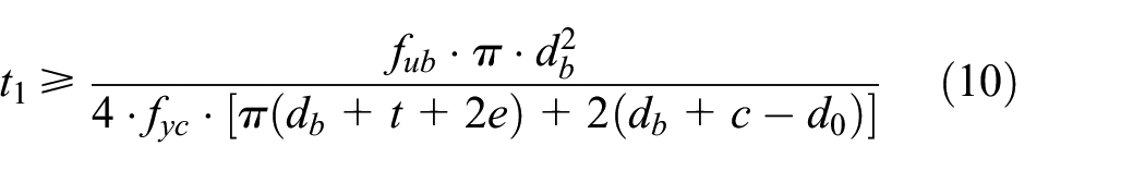
where fub is the ultimate tension strength of the steel bar. Ab is the cross-section area of the steel bar. To prevent tension failure of the coupler, the coupler wall thickness t1 should satisfy
The shear yield strength of coupler should satisfy:

and

where Avc0 is the longitudinal net cross-section area of the swaged coupler.
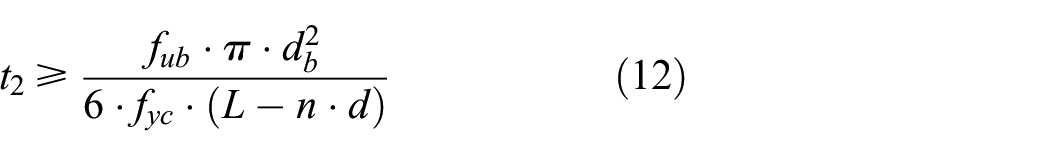
To prevent shear failure of the coupler, the coupler wall thickness t2 should satisfy
The coupler wall thickness t takes the maximum value of t1 and t2 as

The length, width, and height of the coupler are calculated by equations (1), (3) and (4).
Verification of design method for coupler
To verify the design method of coupler, additional TIE constraints between the rebars and the coupler are applied to the above FEM to make sure the failure occurs in the coupler, as shown in Figure 15(b). The steel rebar and the coupler are tied together in a small region to transfer the tension force from the steel rebar to the coupler thoroughly.
If the rebar is made of HRB400 and the coupler is made of Q345B steel, the required coupler wall thickness calculate by equation (10) should be great than 4.79 mm to prevent the tension failure at the net section. Take the coupler length as 90 mm, the required coupler wall thickness should be great than 3.93 mm to prevent the shear failure at the net section. Take the coupler length as 240 mm, the required coupler wall thickness should be great than 1.35 mm to prevent the shear failure at the net section. That is, the coupler wall thickness calculated by equation (13) should be 5 mm at least.
The OC-T1 and OC-T2, as listed in Table 3, fail by the tension failure of the coupler, for the coupler wall thickness of 2 mm and 4 mm are bigger than 1.35 mm that is required for preventing the shear failure of the coupler and are less than 4.79 mm that is quire for preventing the tension failure of the coupler, as shown in Figure 16(a). The OC-T4 also fails by the shear failure of the coupler, for the coupler wall thickness of 2 mm is less than 3.93 mm that is required for preventing the shear failure of the coupler and 4.79 mm that is quire for preventing the tension failure of the coupler. The OC-T3 would not fail by the coupler, for the coupler wall thickness of 6 mm is bigger than 3.93 mm that is required for preventing the shear failure of the coupler and 4.79 mm that is quire for preventing the tension failure of the couple.

Verification of proposed design metnod: (a) failure modes of OMWSC with different wall thickness and (b) failure modes of OMWSC with different wedge number.
Design method for wedge and verification
Design method for wedge
The wedge length should be greater than the coupler height as

Although the wedge diameter affects the ultimate tension resistance of the OMWSC, to simplify the manufacture of the wedge and the coupler, the wedge diameter is fixed to 12 mm. The recommended extrusion ratio is 18.75%, the corresponding rebar gap is 6 mm


Since the OMWSC with two wedges could not prevent the slippage of the rebar from the coupler, an OMWSC with three wedges is recommended

In order to fully utilize the efficient contact length, the center distance of wedges is recommended to be Ue and the edge distance to be 0.5Ue that is calculated by equation (6). The coupler length L is

Verification of design method for wedge
To verify the design method equations (14a) to (14e) for the wedge, specimens with wedge number of 1, 2, and 3 are studied.
The OC-W1 and OC-W2, as listed in Table 3, fail by steel bar slipping failure and the OC-W3 with three wedges fails by steel bar tension failure. For comparison, the load-displacement curve of OC-B4, a rebar without OMWSC is also shown in Figure 16(b). The load-displacement curve of OC-W3 coincides with that of OC-B4, which demonstrates that the OMWSC with three wedges is an ideal rebar mechanical connection.
Conclusions
The behavior of steel rebars connected with Offset Multi-Wedge Swaged Coupler (OMWSC) is investigated using a verified Finite Element Model (FEM). Studied parameters included the rebar surface type, the wedge diameter, the steel rebar diameter, the overlap ratio of the wedges that is defined as the ratio of wedge center distance to the effective wedge distance, the extrusion ratio that is defined as a half of the wedge diameter to the gap of the two connected rebars, and the edge distance. Design equations for the wedge diameter, the wedge number, the wedge distance, the coupler cross-section, and the coupler lengths of an OMWSC are proposed. Verification of the proposed design methods shows the OMWSC designed using the proposed method would not fail prior to the failure of steel bars. The following conclusions are drawn:
With the increase of extrusion ratio, the ultimate tension resistance provided by the OMWSC increases. The extrusion ratio of 18.75% is recommended, for a higher extrusion ratio would cause difficult to the wedge installation.
The wedge diameter and the rebar diameter have little influence on the ultimate tension resistance of OMSWC. The wedge diameter of 12 mm is recommended.
Insufficient wedge middle distance and wedge edge distance would weaken the ultimate tension resistance of the OMWSC. The wedge middle distance of Ue and the edge distance of 0.5Ue are recommended. The OMWSC with three wedges could provide enough tension resistance to assure the tension yielding failure of the rebar.
Design equations for coupler and the wedge are proposed and verified using FEM. The tension failure and shear failure of the coupler, and slippage of rebar are all prevented.
This studies only presented the uniaxial tension behavior of the OMWSC. The behavior of OMWSC under cyclic loads should be further studied and Tthe proposed design method cannot be applied to connections under cyclic loads and the behavior of OMWSC under cyclic loads should be further studied.
Footnotes
Declaration of conflicting interests
The author(s) declared no potential conflicts of interest with respect to the research, authorship, and/or publication of this article.
Funding
The author(s) disclosed receipt of the following financial support for the research, authorship, and/or publication of this article: The authors wish to acknowledge supports from the National Natural Science Foundation of China (51578322, 51608305).