
Abstract
Seawater and sea sand concrete (SWSSC) filled ultra-high performance concrete (UHPC) tube (SFUHPC tube) column is a cement-based tubular composite column, which combines the excellent compressive strength and toughness of UHPC and lateral confining action from fiber reinforced polymer (FRP) hoops. The novel composite system has the potential to be used in marine engineering. The aims of this paper focus on evaluating the seismic performance of SFUHPC tube columns for being designed in costal and marine engineering. A series of low-cycle reversed lateral loading tests were conducted on five relatively large-scale specimens. FRP hoop volumetric ratio, compressive strength of filling SWSSC, and the types of FRP bar were selected as test parameters in this investigation. The failure modes, hysteretic responses and effects of main parameters were studied and discussed. SFUHPC tube columns exhibited flexural failure mode without visible spalling of the UHPC cover. It is noteworthy that the limit plastic drift ratios of all SFUHPC tube columns exceed the specified limits (0.02) in accordance to the rare earthquake requirement in seismic design code. The current study reveals that the proposed composite columns have acceptable ductility and relatively reliable lateral resistant performance for being used in the marine engineering. From the point of view of seismic performance, filling high strength SWSSC in UHPC tube is acceptable for the proposed composite system.
Keywords
Introduction
The increasing growth of global population has led to huge demand of infrastructure such as buildings, bridges, ports. The consumption of tremendous amount of the raw materials, particularly fresh water and river sand, in normal concrete (NC) are increasingly causing serious environmental problems in recent years (Li et al., 2016a, 2016b; Teng et al., 2011; Xiao et al., 2017). Seawater, sea sand and other marine resources (e.g. deceased coral), as the very rich and easy to be exploited materials, are considered as the replacements of fresh water and river sand in construction industry. Existing literatures reported that the mechanical properties of seawater and sea sand concrete (SWSSC) are generally similar to those of NC, although the properties are influenced by the contents of seashells in sea sand (Chandrakeerthy, 1994; Cui et al., 2014; Ghorab et al., 1990; Katano et al., 2013; Mohammed et al., 2004; Xiao et al., 2018; Yang et al., 2010; Zhang et al., 2019). Therefore, application of SWSSC offers potentially alternative to NC in areas with those marine resources but limited access to river sand and freshwater (Garel et al., 2009; Limeira et al., 2012), especially for marine construction in ocean islands. The adoption of these locally available resources can considerably reduce cost as well as effectively shortening the construction period due to avoid the long-distance marine transportation of materials (Wang et al., 2017).
It is a fact that the chloride ions in SWSSC can lead to the corrosion of embedded carbon steel and eventual destruction of concrete structures (Da et al., 2016; Dias et al., 2008; Olutoge et al., 2014). Therefore, the corrosion resistant materials, such as fiber reinforced polymer (FRP) and stainless steel (SS), are needed for replacing carbon steel in SWSSC structures to overcome the corrosion problem (Li et al., 2016a, 2016b). Structural columns are the most important load carrying components in a building, required to high axial load carrying capacity and necessary ductility. When these materials are used along with SWSSC as compressive members, composite columns based on confinement effect are reasonable structures due to their high-strength, stiffness, and ductility.
FRP hoops (or spirals) confined-SWSSC is an option though this type of columns is not reported in the open literature till now. The similar composite system, circular NC columns internally confined by FRP hoops or spirals, had been investigated by researchers (Afifi et al., 2014a, 2014b; De et al., 2010; Hadhood et al., 2017; Maranan et al., 2016; Tobbi et al., 2012). FRP and SS can also act as external confinements, such as SWSSC-filled FRP tube and SWSSC-filled SS tube. The tube also serves as a permanent framework in casting SWSSC (Chen et al., 2017; Li et al., 2016a, 2016b, 2018a, 2018b; Wang et al., 2017). Relative investigations demonstrated the desirable structural performance (e.g. high load carrying capacity and ductility) of these composite systems.
However, aforementioned SWSSC composite columns have several drawbacks which may hinder their application in offshore engineering. For FRP hoops-confined SWSSC system, concrete cover of the FRP hoops cracks and spalls at low level of loading, and it leads to a reduction of the load carrying capacity (Afifi et al., 2014a, 2014c). This type of columns cannot also be used for prefabrication (Shan et al., 2018). However, for SWSSC-filled FRP tube and SWSSC-filled SS tube, some disadvantages are difficult to avoid due to longtime exposure, including the temperature sensitivity of FRP material and the poor fire resistance of steel tube, respectively. On another hand, SS tube is expensive, leading to relatively high initial cost in construction.
Developing new forms of structural columns is of real need for appropriately and economically using SWSSC in the offshore engineering. Ultra-high performance concrete (UHPC) is a new type of cement-based material with super-high compressive strength, high toughness and excellent durability. UHPC realizes the ultra-high performance through mixing steel fiber, eliminating the coarse aggregates and reducing the water-to-cementitious material ratio (Bonneau et al., 1997; Richard et al., 1995). Existing studies including accelerated tests in laboratory (Graybeal and Tanesi, 2007; Pimienta and Chanvillard, 2004; Zhou et al., 2018) and long-term tests in field (Thomas et al., 2012) have proved that UHPC has excellent durability in marine environmental conditions. Therefore, a new type of SWSSC composite column, named SWSSC-filled UHPC tube (SFUHPC tube) is designed by the authors. In this hybrid system, FRP hoops are arranged in the prefabricated thin UHPC tube and then SWSSC is cast, as shown in Figure 1. To further improve durability, stainless steel fibers instead of ordinary steel fibers are used in UHPC tube.
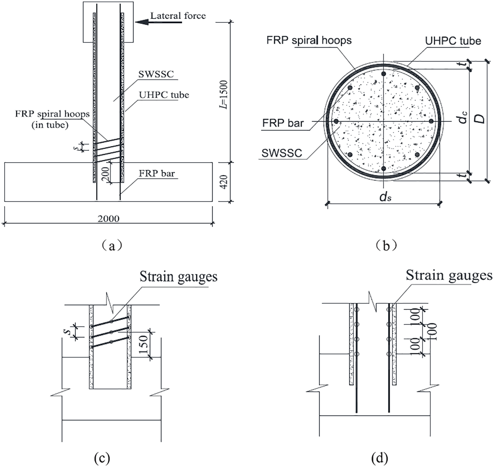
Design of SFUHPC tube column (unit: mm): (a) SFUHPC tube column, (b) cross section, (c) strain gauges on hoops, and (d) strain gauges on longitudinal bars.
SFUHPC tube columns have several special advantages for use in marine engineering. Unlike the FRP hoop-confined column, UHPC cover contributes to the load carrying capacity due to its spalling resistance and high strength (Shan et al., 2018). The prefabricated tube also services as the permanent formwork for inner SWSSC during construction. UHPC tube can provide effective protection and then can avoid those disadvantages due to FRP exposure, such as suffering elevated temperature condition. Moreover, the proposed system is much cost effective compared with the SWSSC filled SS tube system.
Recently, axial compression properties of SFUHPC tube stubs were studied (Shan et al., 2020), in which carbon FRP (CFRP) bars were selected as hoops. The results showed that strength and ductility of SFUHPC tube are much higher than those of corresponding conventional CFRP hoop-confined SWSSC specimen, attributing to whole UHPC tube, including UHPC cover, has a significant contribution to the axial load carrying capacity. The proposed hybrid system effectively combines the super high compressive strength of UHPC and confinement effect from CFRP hoops.
Structure columns need to bear the lateral load caused by wave impact, hurricane and earthquake if being used in island engineering. Therefore, the lateral resistant performance of SFUHPC tubes need to be investigated. In this study, five relatively large-size composite columns were performed the low-cycle reversed lateral loading tests in order to investigate the structural behavior and evaluate the seismic performance of the proposed composite system.
Experimental program
Specimen design
Five SFUHPC tube columns were conducted the low-cycle reversed lateral loading test under the constant axial load. All specimens were consistent sizes with outer diameter (D) of 300 mm and height (L) of 1500 mm, corresponding to the distance between the lateral loading point and the top of the footing, as shown in Figure 1(a).
The thickness of the UHPC tube (t) was 25 mm and the FRP spiral hoops were placed in the mid-thickness section (t/2), and the center diameter of the FRP hoops (ds) was equal to 275 mm. Eight longitudinal FRP bars were evenly arranged in the inner concrete, as shown in Figure 1(b).
Table 1 shows the testing matrix, in which the variables include spiral spacing (s) in the UHPC tube (20 mm, 40 mm, and 60 mm, corresponding to different hoop volumetric ratio), type of FRP bar (carbon FRP (CFRP) and basalt FRP (BFRP)) and strength grades of inner SWSSC (C40 and C60 according to the Chinese standard). Each specimen in Table 1 is named as type (C and B for CFRP and BFRP hoops, respectively) followed by spiral spacing in UHPC tube (s) and strength grade of inner concrete (L and H corresponding to C40 and C60, respectively). For example, C40L designates the tubular composite specimen with 40 mm spiral spacing in UHPC tube, filling SWSSC of C40 grade. B40L is the only specimen reinforced with BFRP bars. Longitudinal reinforcement ratio and the hoop volumetric ratio of B40L were close to those of C40L on the basis of the strength equivalent principle.
Details of specimen and test matrix.
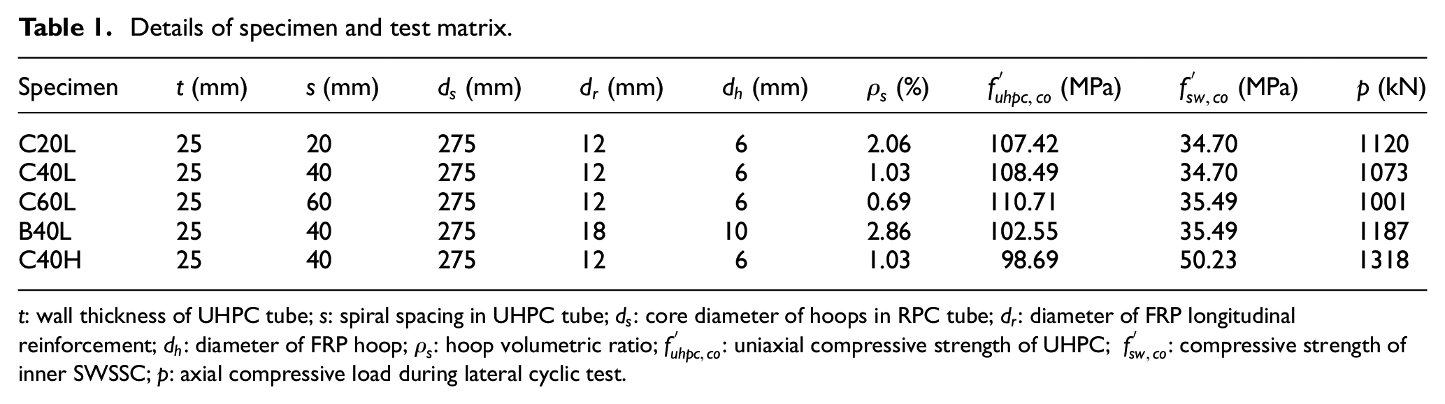
t: wall thickness of UHPC tube; s: spiral spacing in UHPC tube;
Materials
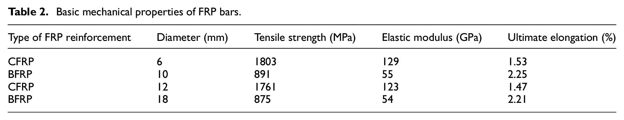
Two types of CFRP bar and BFRP bar with nominal diameter (
Basic mechanical properties of FRP bars.
UHPC tube in this investigation is a typical thin-walled element with dense reinforcement. Therefore, all tubes in the test were manufactured by factory by the spinning process, in which the fresh UHPC was intensively compacted in a rotating mold by centrifugal force, as shown in Figure 2. The raw materials of UHPC used in the spinning process were as follows: Grade 42.5 ordinary Portland cement; silica fume (20,500 m2/kg); natural sand (maximum nominal sizes of and 3 mm); superplasticizer (polycarboxylate); thickening agent (methylcellulose); stainless steel fibers (12 mm long and 0.2 mm diameter); polyvinyl alcohol (PVA) fibers (18 mm long and 45 μm diameter). The mix proportion was as follows: cement: silica fume: sand: steel fiber (volume dosage): PVA fiber: superplasticizer: thickening agent = 1.0:0.25:2.1:0.02:0.004: 0.03:0.0005, with the water to binder ratio (W/B) of 0.17. The compressive strength of UHPC was 123.2 MPa tested on the three cubes (100 mm × 100 mm × 100 mm) after heat treated at 90°C for 48 h. Three UHPC prisms (100 mm × 100 mm × 300 mm) were cast and cured at the same time and conditions as each tube. The average of compressive strength
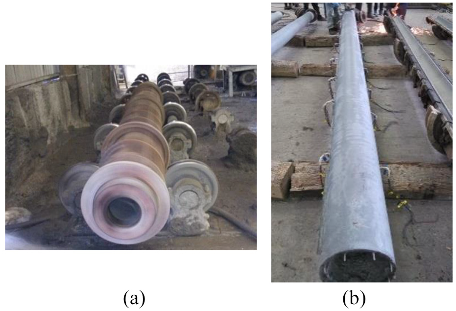
Process of UHPC tube: (a) spinning process and (b) UHPC tube.
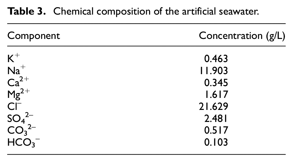
The water used for inner SWSSC was artificial seawater prepared in the lab according to the existing study on seawater from the South China Sea (Wang et al., 2017), and its composition was presented in Table 3. The sea sand obtained from Daya Bay, China, was used as fine aggregates. The rest of the raw materials included ordinary Portland cement, crushed granite stone with a maximum size of 25 mm as coarse aggregate and superplasticizer (polycarboxylate). The mix proportion of C40 was as follows: 1:0.61:2.07:3.38 for cement:seawater:sea sand:gravel, respectively. The mix proportion of C60 was as follows: 1:0.38:1.58:2.58:0.0085 for cement:seawater:sea sand:crushed stone:superplasticizer, respectively. The average compressive cylinder strength at 28 days of C40 and C60 were 35.6 MPa and 52.3 MPa, respectively, according to ACI Committee 318:2008 (2008).
Chemical composition of the artificial seawater.
Specimen preparation
The SFUHPC tube specimens were fabricated by laboratory staff. Firstly, the FRP bar cages were assembled, as shown in Figure 3(a). Secondly, the UHPC tube was erected and embedded 200 mm into the footing to provide sufficient development length for transferring the load, as shown in Figure 1(a). Then, SWSSC was poured in the footing and the hollow UHPC tube, respectively. A typical composite column is shown in Figure 3(b). Three cylinders with 150 mm diameter and 300 mm height were produced at the same time for each column when the inner concrete was poured and then cured in the same conditions. The average of compressive strength from three cylinders represented the uniaxial compressive strength of inner concrete
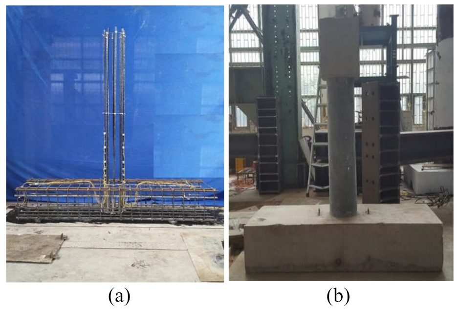
Process of SFUHPC column construction: (a) FRP bar cage and (b) SFUHPC tube specimen.
Test setup and instrumentation
All columns were tested using a special test setup, in which the specimen was tested as style of vertical cantilever, as shown in Figure 4. Lateral load was applied through a pseudo-controlled hydraulic actuator. By post-tensioning two high-strength steel rods with two hydraulic hollow jacks, a constant axial load was applied on the top of the specimen. The axial load was monitored by load cells placed and lateral force was recorded by the built-in load cell of the actuator. The lateral displacement was measured by a separate linear potentiometer.

Illustration of test setup (unit: mm).
Nine strain gauges were adhered on three continuous loops in the UHPC tube before casting UHPC in the plant, as shown in Figure 1(c). For measuring the strain distribution of longitudinal FRP bar, twelve strain gauges were adhered on two FRP bars in the loading plane, starting from the top of footing, as shown in Figure 1(d).
All strain points, including lateral displacement and load, were simultaneously recorded by a data acquisition system at rate of 2 Hz.
Testing procedure
During the test, the specimen was first subjected to a constant axial load to simulate the dead load acting on the column. The axial load P was taken as 0.2 Nu, where Nu is the axial load carrying capacity of the SFUHPC tube column decided through a calculation method proposed by authors (Shan et al., 2020), as follows.

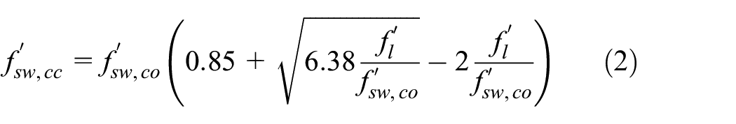
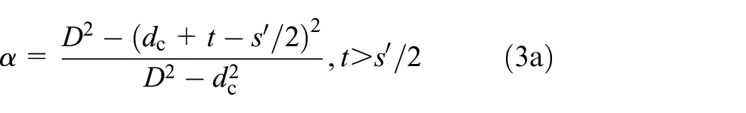


where,
A reversed cyclic lateral load was applied incrementally in displacement control. For the first three single cycles, the increment of peak drift ratio was set as 0.25%; where drift ratio, θ, was defined as ratio of the lateral displacement Δ and the clear length L. Then, the load run for 3 cycles at the peak drift ratio of 1%, 1.5%, 2%, 2.5%, 3%, 4%, 5%, 6%, 7%, 8%, and 10%, respectively, until that the specimens was judged as unsuitable for further loading (Shan et al., 2020).
Experimental results
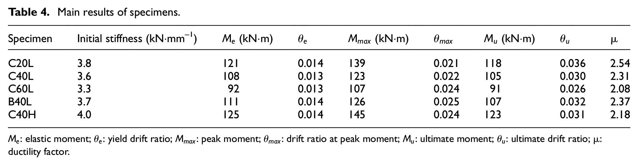
The failure mode and the hysteretic lateral force-drift ratio response of each model column are exhibited in Figures 5 and 6, respectively. Table 4 also presents the basic test data of all specimens, where each value is the average of the push and the pull directions. It should be noted that the ultimate state of the specimen is determined as the state when the lateral load carrying capacity (bottom moment) dropped 15% from the peak value (Park, 1989; Xu et al., 2017) in this study, as illustrated in Figure 7.
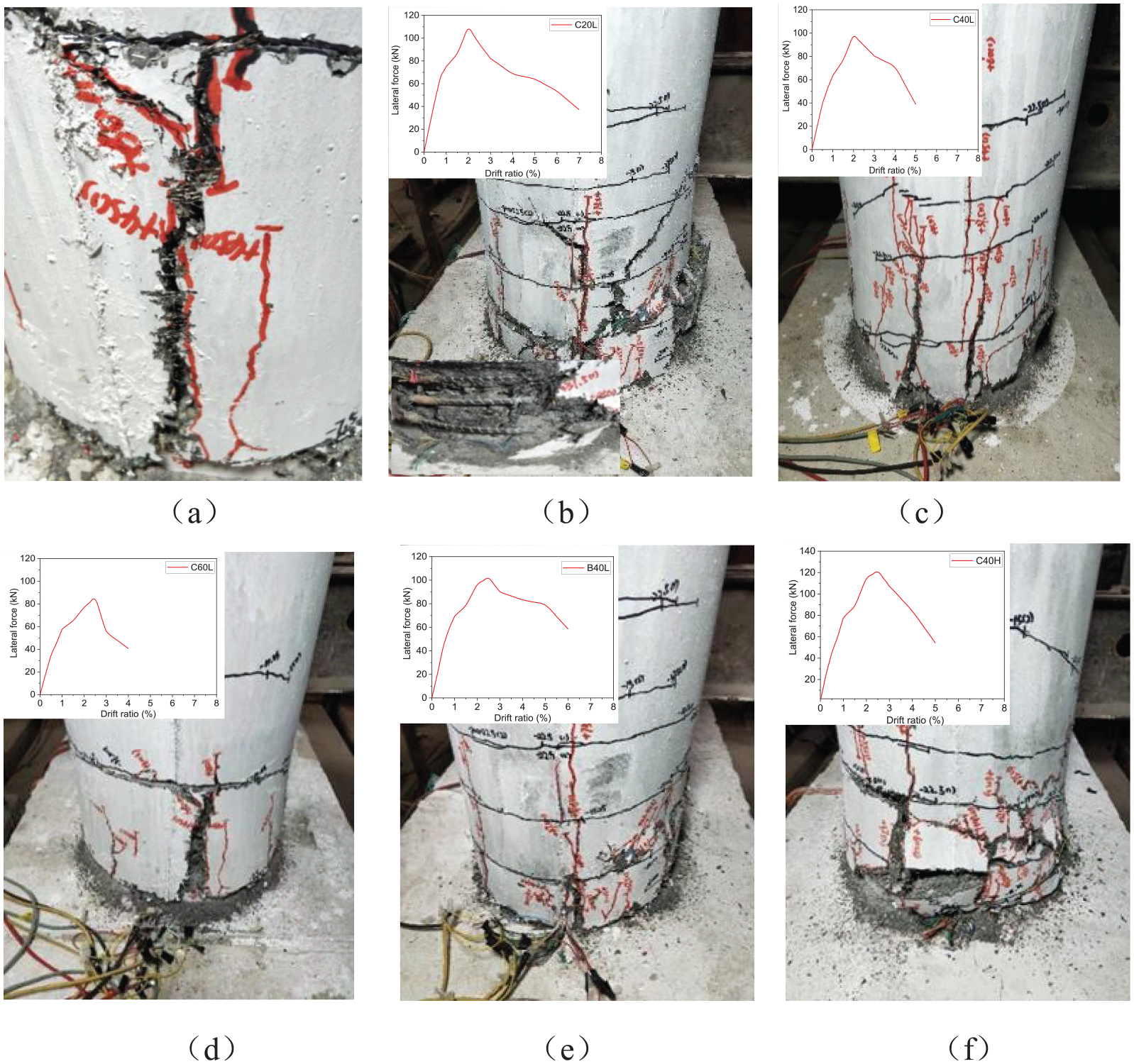
Failure patterns of specimens: (a) details of cracking, (b) C20L, (c) C40L, (d) C60L, (e) B40L, and (f) C40H.
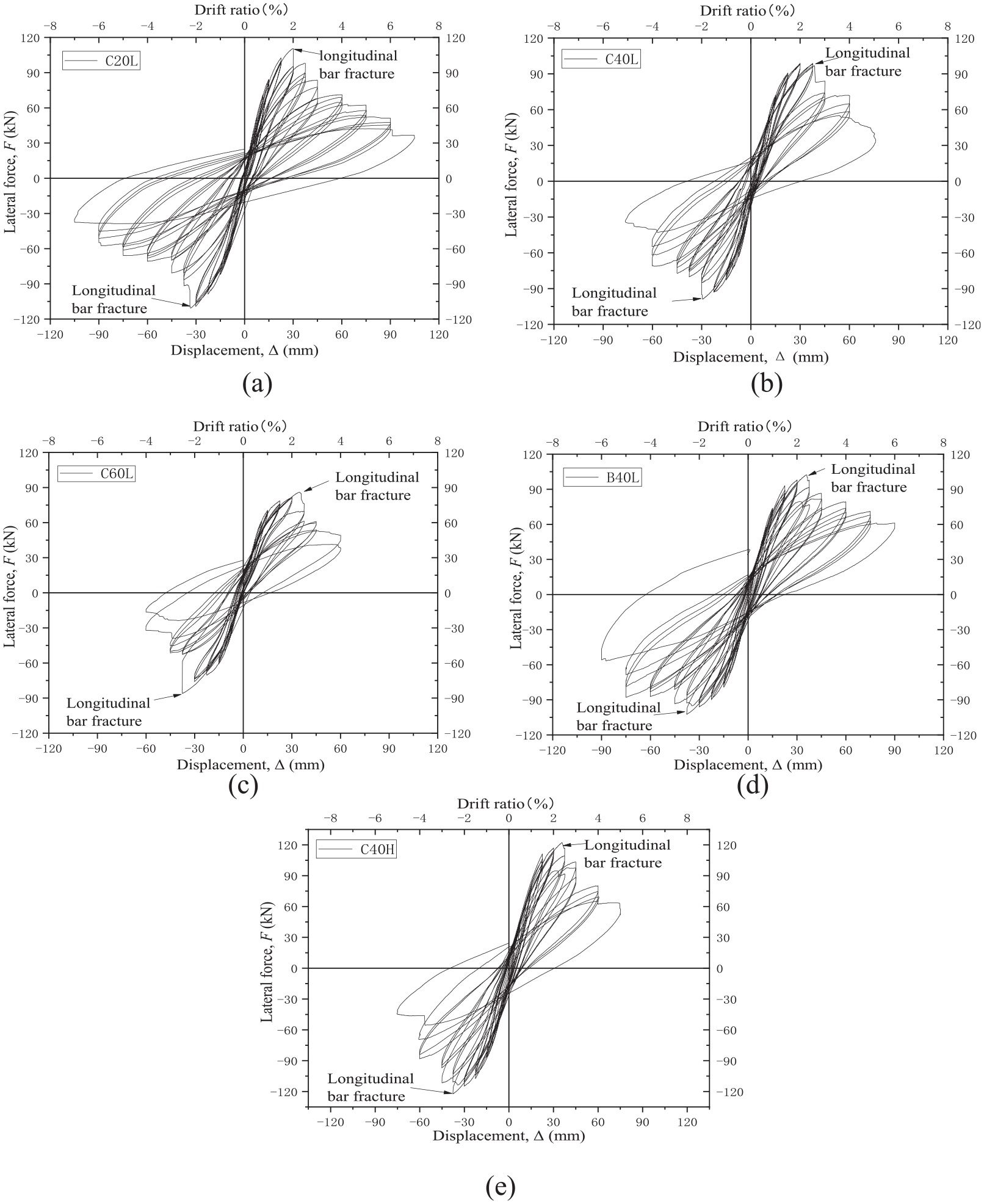
Hysteretic loops: (a) C20L, (b) C40L, (c) C60L, (d) B40L, and (e) C40H.
Main results of specimens.
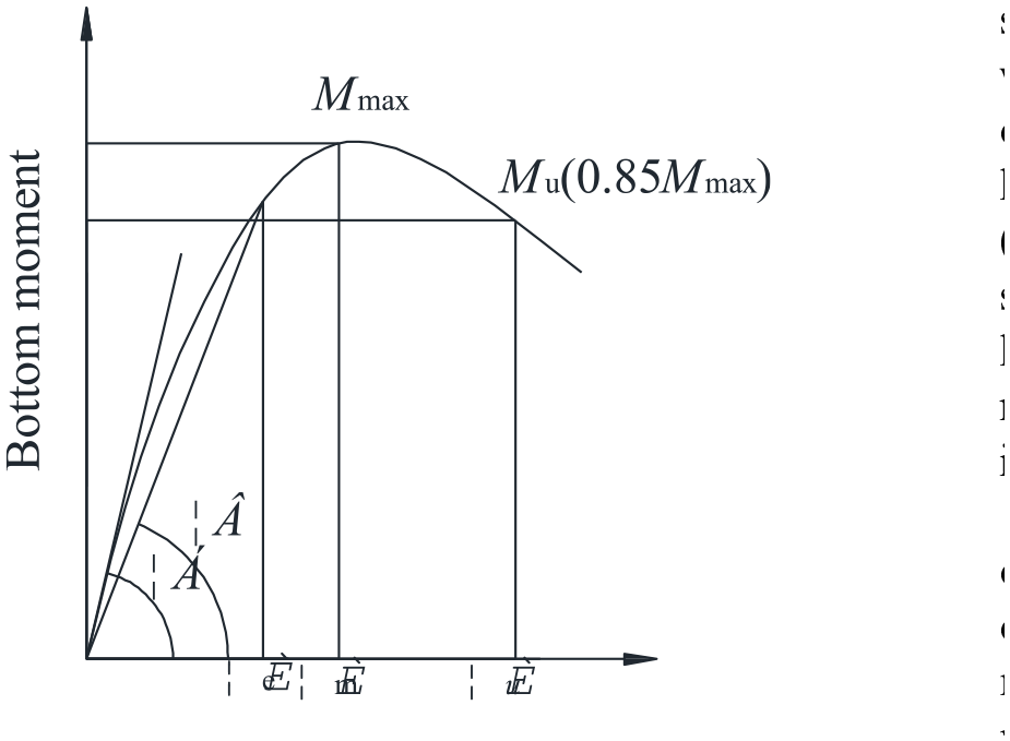
Characteristic parameter definition.
Failure modes
In Figure 5, only a portion of length above the footing is shown for clearer illustration of the cracking patterns, in which the relationship between the average lateral force and the lateral drift ratio is also presented for each specimen. Generally, SFUHPC tube columns exhibited typical bending shear failure characteristic, similar to the ordinary reinforced concrete column (Shan et al., 2006). Taking C20L as an example, the first transverse crack could be observed when the drift ratio reached about 1%. Several cross diagonal cracks appeared at drift ratio of 2%. Then, the thin cracks increased in length and number, rather than widening, throughout subsequent cycles. When the draft ratio reached 5%, the UHPC tube occurred visible bulge. However, obvious spalling of UHPC cover is not observed due to the bridging action of fibers in UHPC, as shown in Figure 5(a). When the drift ratio reached about 7%, with, CFRP hoops ruptured with a loud noise, and the test was terminated, as shown in Figure 5(b).
For the composite columns with increasing hoop spacing in the UHPC tube, the more sparse transverse cracks on the surface can be observed after test, comparing failure modes in Figure 5(b) to (d). For the B40L reinforced by BFRP bars, relatively more crack can be seen on the surface compared with the corresponding specimen with C40L, as shown in Figure 5(e).
For the composite column C40H, filled with high strength SWSSC, the cracks on tube is relatively serious compared with C40L, filled by normal strength SWSSC, as shown in Figure 5(f).
Hysteretic response
Basic feature of hysteretic curves of all specimens is a shuttle shape with obviously pinched phenomenon. Typical hysteretic response of SFUHPC tube columns includes three stages of the initial elastic stage, a relatively slow ascending stage and the relative fast declining stage. In the initial stage, before the UHPC tube cracked, the hysteretic loops exhibit a narrow and elongated shape, corresponding to slight plastic deformation and negligible energy dissipation. Next, the lateral stiffness decreases and the hysteretic loops are relatively plumped gradually, indicating the increasing of energy dissipation in the second stage. Then, the hysteretic loops show a sudden drop at the peak load caused by the rupture of the longitudinal FRP bars. Finally, the hysteretic loops present a relatively slow descent until the end of the test.
Compared with C60L, C40L, and C20L (Figure 6(a)–(c)), the hysteretic loops gradually become relative plumper as the spacing of hoops in the tube reduces from 60 mm to 20 mm. It means that the energy dissipation capacity can be improved in a certain degree through increasing hoop volumetric ratio in the tube.
Compared with B40L and C40L in Figure 6, it can be seen that the hysteretic loops of the former are relatively plumped, indicating that using BFRP bars as reinforcement can improve the energy dissipation capacity of SFUHPC tube system. The result suggests that the deformable FRP bar is more efficient for improving seismic behavior of this type of composite columns.
C40L and C40H were filled with different strength SWSSC in the tubes. The peak load and the initial stiffness of C40H are greater than those of the C40L, especially for the peak load, as shown in Figure 6(b) and (e). On the other hand, the hysteretic loops are relatively more pinched for the specimen filled with higher strength SWSSC. The phenomena may be caused by increasing of the axial load P and decreasing of the confinement ratio, defined as the ratio of lateral confining stress to compressive strength of inner concrete.
Strain analysis
Figure 8 shows the lateral load-strain development of the longitudinal FRP bars in inner SWSSC and hoops in UHPC tube, which were recorded by the strain gauges approximately 100 mm and 130 mm above the footing, respectively.
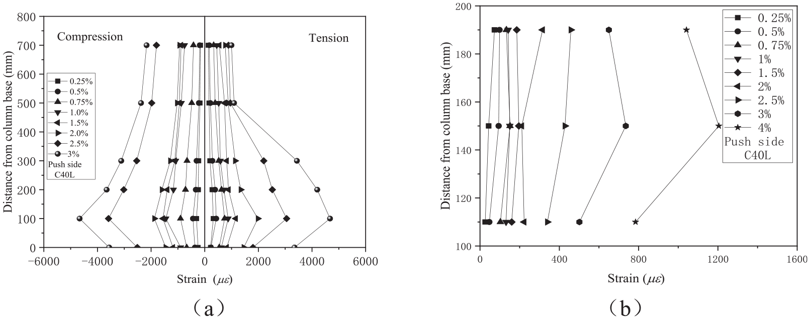
Strain development of FRP reinforcements in C40L: (a) longitudinal FRP bars and (b) FRP hoops.
Generally, the load-strain developments of all SFUHPC tube columns are similar with each other. So C40L is selected to analyze the strain behavior of FRP bars. Figure 8(a) shows the strain distribution of longitudinal CFRP bars along the height under different loading levels, where the compressive strain is negative and the tensile strain is positive. The values of strain decrease along the column height and increase with increasing drift ratio. However, the strain value of the first measuring point at the foot is relatively lower, due to the confinement effect caused by the stub (Paultre et al., 2001). It can also be observed that the strains in the plastic hinge zone, corresponding to a length of column diameter above the footing, develop much faster than other measuring points, due to significantly lateral expanding of SWSSC in this zone.
The hoop strain distribution of C40L at each level of drift ratio is presented in Figure 8(b). Development of the hoop strain can be ignored before the drift ratio reaches 2.0%. Then, the strain of hoops increases significantly with the increasing of the drift ratio, meaning that the FRP hoops in the UHPC tube provide effectively lateral confining action during the cyclic revised loading. It also can be seen that the maximum strain of the CFRP hoop is significantly less than the ultimate strain from the tensile test on straight bars. The similar results were also reported in tests on concrete columns confined by FRP hoops (Afifi et al., 2014c).
Skeleton curves
Figure 9 presents the skeleton curve of each column corresponding to the envelope curve of the first cycle under each level of the drift ratio. All the skeleton curves of SFUHPC tube columns show a good symmetry in the push and the pull directions. The typical skeleton curve exhibits almost a linear line before cracking of the UHPC tube followed by an obvious non-linear change. Then, the lateral stiffness, the slope of the skeleton curve, gradually decreases before reaching the peak load. After the peak load, the lateral load declines rapidly till failure of the column.
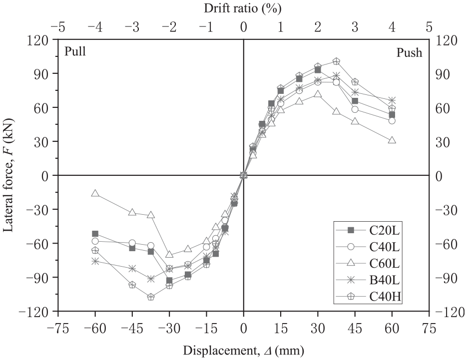
Skeleton curves of specimens.
In Figure 9, it can be found that the lateral load carrying capacity and the initial stiffness of SFUHPC tube columns increase with decreasing of the spiral spacing in the tube, where the initial stiffness is based on the elastic slope of the skeleton curve. For example, the peak lateral load of C20L is about 12.8% and 30.3% higher than those of C40L and C60L, respectively. The main reason is that increasing hoop volumetric ratio in the tube can enhance the lateral confinement to inner SWSSC. However, this improvement is quite limited compared with its effect on the axial load carrying capacity reported by writers (Shan et al., 2020).
The skeleton curves experience a certain difference between the specimens with different types of FRP bar and SWSSC. For instance, the lateral resistance and the deformability improve by using BFRP bars in the tube and the inner concrete. Compared with C40L, the peak lateral load and the initial stiffness of C40H increase about 22.5%, 26.7%, respectively. However, the deformability shows a slight descent with the composite column filled with high strength SWSSC.
Lateral load carrying capacity degradation
In the paper, the lateral load carrying capacity ratio is used to evaluate the stability of lateral resistance of the composite columns that is defined as the lateral force ratio between the last cycle and the first cycle at each level of drift ratio. Degradation curves are shown in Figure 10, where values at the first four points are equal to 1.0 due to only one cycle at those four drift ratios.

Strength degradation curves.
In Figure 10, the load carrying capacity degradations of SFUHPC tube columns are almost identical before the drift ratio reaching 2.0%, corresponding to the cracks of UHPC tube increased in length and number instead of in width in this stage. Then, the load carrying capacity degradation is more dramatic as increasing the hoop spacing in the tube, through comparing the curves of C20L, C40L, and C60L. It proves that increasing lateral confinement is beneficial to maintain the stability of residual load carrying capacity of this composite column.
On the other hand, the compressive strength of inner SWSSC and the type of FRP bar have obvious influence on the load carrying capacity degradation. It can be seen that the load carrying capacity ratio of C40H declines faster and more seriously than that of C40L after the point of draft ratio equal to 2%, due to a relatively higher brittleness for high strength concrete. Compared with the C40L, the load carrying capacity ratios of the B40L are significantly lager after drift ratio beyond 2%, though two columns have a similar lateral confining level. This result indicates that the deformability of FRP bar is more important than its strength for maintaining the stability of lateral resistance under earthquake.
Discussions on deformability
Ductility
As an important index for evaluating seismic performance, ductility reflects the inelastic deformability of a structural column without significantly losing its lateral load carrying capacity, and it is usually quantified by the ductility factor. Generally, the ductility factor of ordinary reinforced concrete columns is defined as the ratio of the yield displacement and the ultimate displacement. Existing investigations reported that the concrete columns reinforced by FRP bars have not a clear yield characteristics under the low-cycle reversed lateral loading (Ali and El-Salakawy, 2016; Tavassoli et al., 2015). Therefore, the ductility factor, μ is decided by the ratio of the elastic drift ratio and the ultimate drift ratio in this study, as follows,

where,
Figure 11 presents the comparison of the ductility factor. For the SFUHPC tube columns, the ductility factor increases with the densifying spiral spacing in the UHPC tube. The μ of C20L is about 10.1% and 19.0% higher than those of C40L and C60L, respectively, suggesting that enhancing the lateral confining pressure can improve the deformation capacity of this type of composite columns.
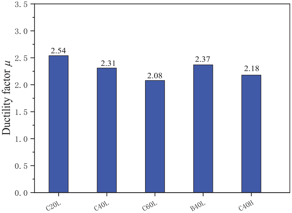
Comparison of ductility factor.
In Figure 11, the μ of the specimen filled by C60 SWSSC (C40H) is only about 3% smaller than that of the specimen filled by C40 SWSSC (C40L), meaning that the ductility of SFUHPC tube column almost does not decreases with filling high strength SWSSC in UHPC tube. The result is different from the observation from the seismic tests on the conventional reinforced concrete columns, in which the ductility decreased significantly and became poor by using HSC (Shi et al., 2014; Xiao and Henry, 2002). It suggests that the brittleness of HSC is improved in the SFUHPC hybrid system, due to the excellent deformability of UHPC tube and the confining action from FRP hoops.
It also can been observed that the μ of the B40L is about 7% higher than that of the C40L, proving again using deformable BFRP bars is beneficial to the ductility of the SFUHPC tube column. Compared with CFRP hoops, BFRP hoops can provide increasing confining pressure for concrete core in a relatively larger range of lateral expansion. Therefore, the deformable FRP hoops are more efficient than stiffer ones for improving the seismic performance of SFUHPC tube columns.
According to the design requirement of Chinese seismic design core (GB 50011-2010, 2010), the limit plastic drift ratio
Energy dissipation
Energy dissipation capacity is another important factor for estimating the seismic performance of the proposed composite system. In this study, the cumulative energy dissipation is utilized for an evaluating parameter and calculated on the basis of the area enclosed in the first hysteretic loop at each level of drift ratio (Zohrevand and Mirmiran, 2012).
In Figure 12, it is clear that the cumulative energy dissipation of the SFUHPC tube columns increases following increasing the hoop volumetric ratio and the strength of SWSSC. For example, the cumulative energy of C40H is about 1.34 times as much as that of C40L at drift ratio of 4%, different to the case of HSC usage in the conventional reinforced concrete columns.

Curves of cumulative dissipated energy.
Conclusion
In this study, five relatively large-scale specimens were conducted the low-cycle reversed lateral loading test for evaluating the structural performance of SWSSC filled in UHPC tube (SFUHPC tube) columns. Based on the test results and analysis, the main conclusions are drawn as follows:
(1) SFUHPC tube columns exhibited flexural failure mode under cyclic reversed lateral loading, where the plastic hinge formed near the root about a diameter height. Failure feature of the composite columns were marked by small and multi-cracking, without UHPC cover spalling or crushing.
(2) The hysteretic curves of SFUHPC tube columns exhibited obviously pinched phenomenon. Using deformable BFRP bars in enhancing SFUHPC tube columns is more efficient for improving seismic behavior compared with using relatively stiffer CFRP bars.
(3) Research results reveal that the main seismic properties of this proposed composite column, including the initial stiffness, the lateral load carrying capacity, the ultimate lateral displacement and the cumulative dissipated energy, are improved as increasing the FRP hoop volumetric ratio in tube.
(4) The limit plastic drift ratio of SFUHP tube columns varies from 0.025 to 0.035 under the test conditions, and that exceeds the ductility requirement (0.02) of the rare earthquake in accordance with the Chinese seismic design code (GB 50011-2010, 2010).
SFUHP tube columns exhibit acceptable ductility and relatively reliable lateral resistant performance if being used in the island engineering. From the point of view of seismic performance, filling high strength SWSSC in UHPC tube is acceptable for the proposed composite system.
Footnotes
Acknowledgements
The research was executed at the MOE Key Laboratory of Building Safety and Efficiency, Hunan University.
Declaration of conflicting interests
The author(s) declared no potential conflicts of interest with respect to the research, authorship, and/or publication of this article.
Funding
The author(s) disclosed receipt of the following financial support for the research, authorship, and/or publication of this article: This work was supported by National Natural Science Foundation of China (51678228, U1806225).