
Abstract
Recycled lump concrete (RLC) made with demolished concrete lumps (DCLs) and fresh concrete (FC) provides a solution for effective waste concrete recycling. To promote the development of precast RLC structures, this study tested a new type of connection for precast concrete columns: connecting the upper and the lower halves of columns with bent longitudinal reinforcements and structural adhesive. In this work the behavior of precast RLC columns with the new connection was studied under axial compression. The axial compressive strength of nine two-part columns was tested. The effects of the degree of bending in the longitudinal reinforcement, the replacement ratio of DCLs and the stirrup spacing were investigated. Tests showed that: (1) the failure mode of precast concrete columns is different from that of cast-in-place columns; (2) when the strength of the waste concrete is close to that of the fresh material, there is no significant difference in the axial compression performance of either precast or cast-in-place columns; (3) the bent longitudinal reinforcement causes the axial load bearing capacity of precast concrete columns to be 4.2%–12.3% lower than that of a similar cast-in-place column; (4) reducing the stirrup spacing has little effect on a precast column’s axial load bearing capacity and ductility; (5) when using Chinese and American codes to predict the axial load bearing capacity of the column, the predicted value should be multiplied by a reduction factor.
Keywords
Introduction
Precast concrete structures have distinct advantages over cast-in-place concrete structure in terms of better quality control, speed, cost, and less environmental pollution (Belleri et al., 2015; Lu et al., 2019; Nikbakht et al., 2014). The performance of a precast concrete structure depends heavily on the mechanical properties of the connections among its precast elements (Kurama, 2018), a matter receiving widespread attention.
Precast concrete frames are among the most widely-used types of precast concrete structures (Guan et al., 2018; Priestley, 1991; Saqan, 1995). Restrepo et al. (1995) have tested the mechanical properties of on beam-to-column joints connected by cast-in-place concrete and shown that a precast version can achieve performance similar to that of cast-in-place construction. Parastesh et al. (2014) used cast-in-place concrete to connect beam-to-column joint with diagonal reinforcement was arranged to increased the strength of the joints and angle steel used as a temporary support. The test results showed that precast components have good structural integrity and higher bending strength, initial stiffness, ductility, and energy dissipation capacity than that of cast-in-place components. It should be pointed out, however, that although the precast setup showed good integrity, the layout of reinforcement in the joints’ core was complex. Proper pouring and vibrating could be difficult. Installing the temporary supports would also increase construction cost and complexity.
Yee (1968) invented a grout sleeve connection in 1968 which is now widely used in building precast concrete structures. Yan et al. (2018) has shown how grout sleeves can be used to connect reinforcements at beam-to-column joints. The beam reinforcements were connected by fully-grouted sleeves and the column reinforcements were connected by half-grouted sleeves. Experiments showed that the seismic performance of precast specimens joined in this way was similar with that of cast-in-place specimens. However, the cost of grout sleeve connections is relatively high and testing the quality of the grout material after grouting is difficult.
Weld connection and bolt connection are also widely used in precast structures. Vidjeapriya and Jaya (2013) compared two precast beam-to-column joints with one cast-in-place joint. The former were connected by stiffeners, cleat angles, and bolts. The stiffener was welded to the cleat angle, and the gap between bolts and the bolt holes were filled with isoresin grout. Test results indicated that the precast specimens would deliver satisfactory performance in terms of energy dissipation and ductility. Ghayeb et al. (2017) reports that beam-to-column joints of precast parts connected by steel plates and bolts showed stable load-displacement hysteresis curves and good energy dissipation capacity under simulated seismic loading. But it should be mentioned that the quality of welding on-site is sometimes difficult to guarantee, and that the installation accuracy required of bolted connections may be too high. Therefore, the application of these two types of connections in practical engineering needs to be carefully evaluated in advance.
The beam-to-column connections have been briefly reviewed above, the following will discuss the column-to-column connections. Nzabonimpa and Hong (2018) and Hu et al. (2016) have conducted experiments prepared finite element models of column-to-column connections with steel plates and bolts. They found the bending strength of the connection was sufficient to replace a traditional precast connection. However, the accuracy requirements of bolted connections may be difficult to meet in practice. Tullini and Minghini (2016) considered the grout-spliced connections commonly used column-to-column connections. Zheng (1996), Kuttab and Dougill (1988), and Arango et al. (2018) have studied similar column-to-column connections with longitudinal reinforcement extending from the precast upper (or lower) column unit inserted into reserved corrugated steel ducts in the precast lower (or upper) unit and then grouted in the corrugated steel duct. Tullini and Minghini (2016) conducted bending, shearing, and cyclic bending tests and found that the failure of precast columns with such connections was mainly concentrated at the interface between the upper and lower column units. Zheng (1996) carried out cyclic loading tests on precast columns with such connections and concluded that the bearing capacity of a precast column can be predicted by conventional reinforced concrete theory. Work by Kuttab and Dougill (1988) has confirmed Tullini and Minghini’s (2016) finding that the failure is mainly concentrated near the interface between the upper and lower column units. Arango et al. (2018) has reported that the performance of precast specimens with such connections can be comparable to that of cast-in-place specimens, but Seifi et al. (2016) suggest that the strength and stiffness of precast columns with such connections might be reduced by the ducts reserved for grouting. For this reason, a new type of column-to-column connection with bending reinforcements and structural adhesive has been proposed, the performance in the axial compression were tested in this study.
Structural adhesive has been widely used in aerospace, automobile, civil engineering, and other applications (Feraboli, 2004; Toldy, 2011). Compared with a welded connection, structural adhesive connections have hardly any stress concentration problems (Floor, 2014). However, structural adhesive are rarely used in beam-to-column or column-to-column connections in precast concrete frame structures at present.
The column-to-column connection method studied here is shown in Figure 1. The lower part of the four corner longitudinal reinforcements of the upper column unit are bent and extend vertically downward from the lower end surface of the upper column into vertical holes on the upper end surface of the lower column unit. Each vertical hole corresponds to a bending longitudinal reinforcement from the upper column unit. Structural adhesive is poured into the holes in advance before inserting the longitudinal reinforcement. Compared with a grout splice connection with corrugated steel ducts, the connection shown in Figure 1 is relatively simple to assemble, and the cost of the corrugated steel ducts is saved. The holes in the lower column unit are smaller than those with a steel duct, so there is less weakening of the cross-section. Due to the weak performance of structural adhesive at high temperatures, the distance between the structural adhesive and the column surface is substantially increased by bending the longitudinal reinforcement. That slows the heating rate of structural adhesive in a fire to improve the column’s fire resistance.

Prototype of the precast column.
The thickness of the column-to-column joint studied here was 6 mm, which is less than other similar studies (Arango et al., 2018; Kuttab and Dougill, 1988; Tullini and Minghini, 2016; Zheng, 1996) have assumed (10–25 mm). Zheng (1996) has suggested that a larger joint thickness may weaken the connection. Grout is required in the joint.
In this study, RLC was used in columns. Experimental results describing the axial compressive, eccentric compressive, and seismic performance of cast-in-place RLC columns have previously been published (Teng et al., 2016; Wu et al., 2010, 2018d, 2019; Zhao et al., 2016). Their mechanical behavior is basically equivalent to that of columns cast with conventional concrete. This study assumed that in assessing the strength in axial compression of the connection between upper and lower RLC column units.
In this paper, six precast concrete columns and three cast-in-place concrete columns were tested under axial compression, the effects of the degree of bending in the longitudinal reinforcement, the replacement ratio of DCLs, and stirrup spacing were investigated. The bending in the longitudinal reinforcement was studied in response to stirrup spacing and the replacement ratio of DCLs. Base on those observations, the axial load-bearing capacity of the precast columns was estimated and compared with the concrete code requirements.
Experimental program
Specimens design
Nine columns were tested under axial compression, including six precast concrete columns and three cast-in-place columns. The geometric dimensions and reinforcements of the columns tested are shown in Figure 2. Each precast column consisted of an upper column unit, a lower column unit, and grout pumped into the joint between them.
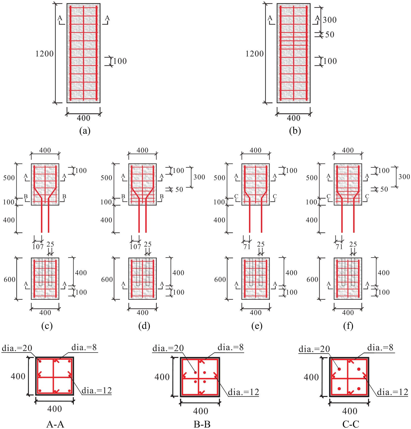
Reinforcement details of columns (unit: mm): (a) C-0-0-100, (b) C-0-20-50, (c) P-107-0-100, (d) P-107-20-50, (e) P-71-0-100, (f) P-71-20-50, Cross-section A-A, Cross-section B-B, and Cross-section C-C.
The cross-sectional size of each column was 400 × 400 mm. Each consisted of two 600 mm units, so the total height was 1200 mm, giving a height to width ratio of 3. The longitudinal reinforcement ratio of each column specimen was 1.07%, which conforms to the provisions of the Chinese code GB 50010-2010 (2010) for the design of concrete structures. The four corner longitudinal reinforcements of the upper column unit were bent 45°. They extended 400 mm out of the lower end of the upper column unit. The diameter of the reserved holes in the lower column unit was 25 mm. The thickness of the concrete covering the stirrups was 25 mm. The joint between the upper and lower halves of the precast column was 6 mm.
The test specimens were cast with two different horizontal projections along the column’s width of the bent section of longitudinal reinforcement (i.e. the distance between the center of the longitudinal reinforcement before and after bending) L = 107 or 71 mm; DCL replacement ratios of η = 0% or 20%; and stirrup spacings of the bent reinforcement s = 50 or 100 mm. The specimens were then designated as M-L-η-s. M represents the production method. For a cast-in-place column M = C, for a precast column M = P. So for example, specimen P-107-20-100 was a precast RLC column, with a 107 mm horizontal projection of the bent section, a DCL replacement ratio of 20%, and 100 mm stirrup spacing. Table 1 gives the details of each specimen tested.
Details of column specimens.

Material properties
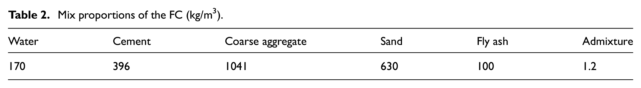
The concrete used in these tests consisted of FC filled with DCLs. The FC used for pouring all of the specimens came from one batch of commercial ready-mixed concrete. Table 2 specifies its mix proportions. Six 150 mm cubes of that ready-mix were poured and cured under same conditions as the column specimens, and their compressive strengths were measured on the test day (Bai et al., 2021).
Mix proportions of the FC (kg/m3).
The DCLs came from a demolished concrete beam. The picture of DCLs is shown in Figure 3. Six 70 mm diameter core samples with 70 mm long were drilled from the beam and tested according to Chinese specification JGJ/T 384-2016 (2016). The cores’ measured compressive strengths were converted to those of equivalent 150 mm cubes. Pneumatic picks and an electric hammer were used to break up the beam into chunks with a characteristic size of 70–90 mm. Table 3 gives the cubic compressive strength of the FC and the DCLs.
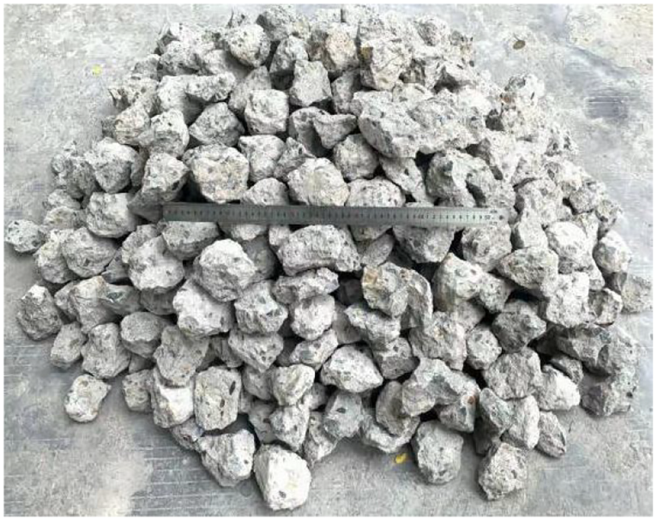
Demolished concrete lumps.
Average compressive strength of FC and waste concrete (MPa).
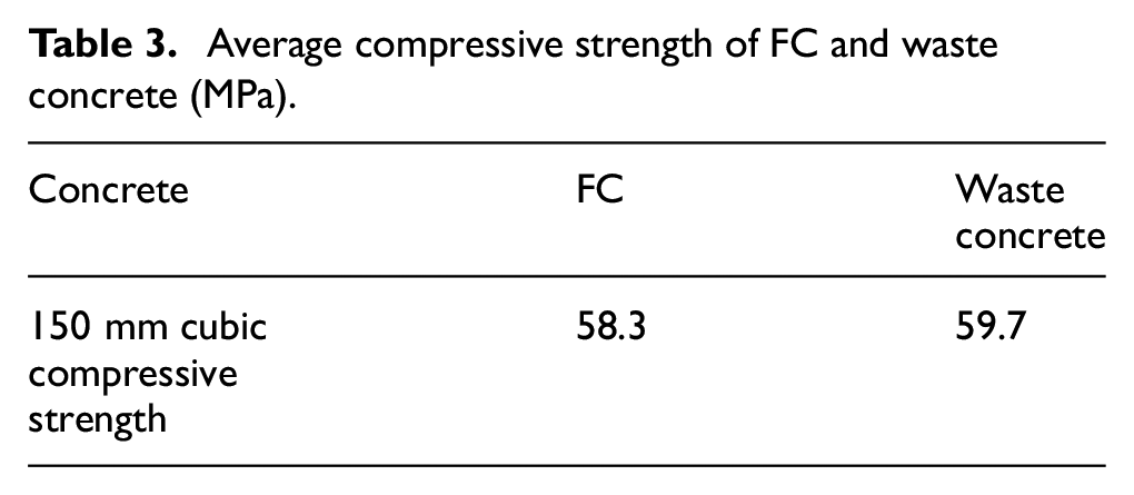
This agrees with the findings of previous studies (Liu et al., 2015, 2017; Wu et al., 2012, 2013, 2014, 2018b, 2018c) that the compressive strengths of both FC and DCLs are within 15 Mpa. The cubic compressive strength concrete combining them can be approximated as

Where,
The measured yield strength and ultimate strength of longitudinal reinforcement and the stirrups used are shown in Table 4.
Mechanical properties of the longitudinal and transverse reinforcements.

The grout was provided by Shenzhen Hongweida Building Materials Co., Ltd. Its water-to-cement ratio was 0.27. The structural adhesive was Hilti model HITRE-500. The curing time for the structural adhesive was 12–24 h at room temperature. Table 5 shows the compressive strengths of the grout measured on the day of the test. The compressive strength and bonding strength of HITRE-500 structural adhesive were provided by Hilti manufacturer.
Mechanical properties of grout and epoxy adhesive (MPa).

Fabrication of specimens
Figures 4 and 5 present the fabrication process. It had two stages: (1) pouring the upper and lower column units; (2) assembling them together. The specimens were poured horizontally. Before pouring, the DCLs were sprayed with tap water to wet them fully (Wu et al., 2008, 2018a, 2018d, 2018e). The tied reinforcement cage put into the mould first, then DCLs and FC were added alternately with continuous vibration to ensure the compactness of the specimen (DBJ/T 15-113-2016, 2016). The extended longitudinal reinforcements of the upper column unit were positioned with the aid of a steel plate made in advance. Four stainless steel pipes with an outer diameter equals to 25 mm were carefully placed in the mould of the lower column unit. They were withdrawn after the concrete had begun to set.
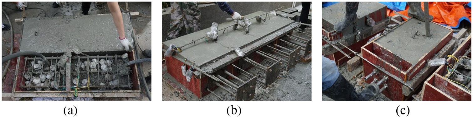
Casting of precast columns and cast-in-place columns: (a) cast-in-place columns, (b) upper part of precast columns, and (c) lower part of precast columns.
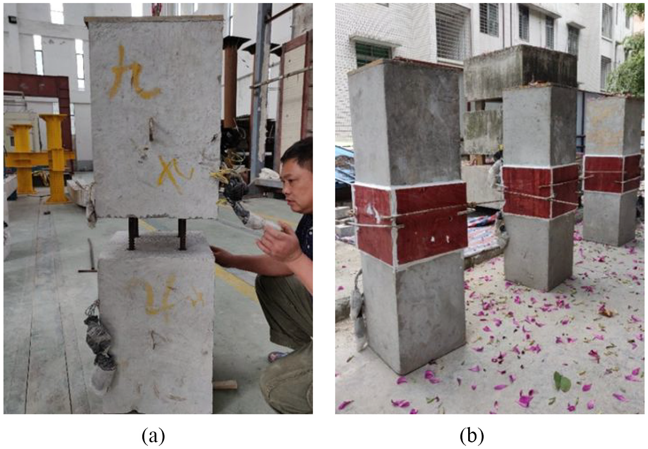
Assembling the upper and lower parts: (a) assembling a precast column and (b) precast columns before grouting.
The assembly was carried out 28 days after upper and lower column units were poured. The upper and lower surfaces of the joint were chipped before assembly to increase their roughness as required by specification JGJ1-2014 (2014). The reserved holes in the lower column unit were cleaned with high-pressure air, and then structural adhesive was injected into them. The extended longitudinal reinforcements of the upper column unit were then inserted. During the assembly process, three 6 mm spacers were placed on the upper end surface of the lower column unit to ensure a 6 mm-wide joint. After the structural adhesive had solidified, grout was pumped into the joint.
Test setup and instrumentation
Four LVDTs were arranged on the side surfaces of each column to measure any axial deformation. An LVDT’s measured length was 1000 mm with 0.01 mm precision over a test range of 50 mm. Strain gauges were arranged on the longitudinal reinforcements and stirrups to measure any strain. Another eight strain gauges were evenly arranged vertically on the surface of each column’s grouting to measure the longitudinal strain at the joints. The specific arrangement of LVDTs and strain gauges is shown in Figures 6 and 7.

Arrangement of strain gauges: (a) cast-in-place column and (b) precast column.
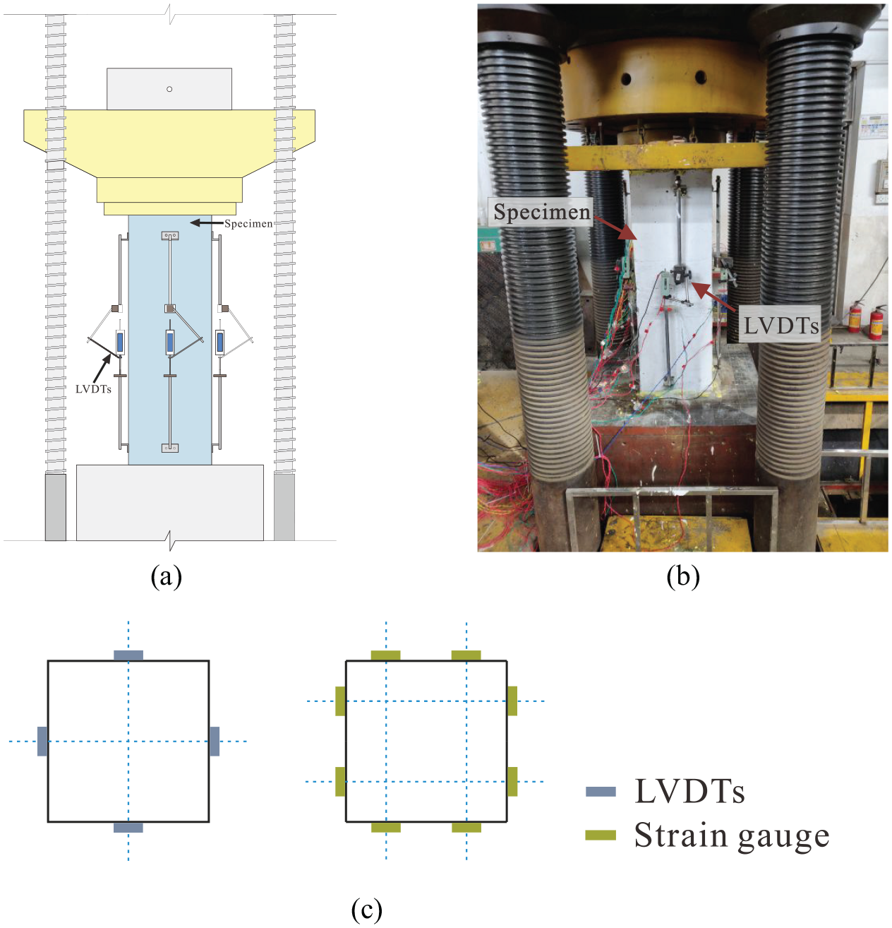
Test setup and the arrangement of LVDTs and strain gauges on the surface of the grouting: (a) test setup, (b) photo of a column ready for testing, and (c) arrangement of LVDTs and strain gauges.
Axial compression tests were carried out on a 15,000 kN electro-hydraulic servo press in the structural laboratory of the South China University of Technology. Before testing, high strength gypsum was used to level the columns’ upper and lower end faces. The columns were then carefully aligned with the press geometry. Displacement control was used with a loading speed of 0.003 mm/s. The loading ended when the load dropped to 70% of the peak load.
Test results and discussion
Crack development and failure patterns
Well-controlled loading was applied to all of the specimens except P-71-20-50, where the press accidentally failed. Figure 8 shows the typical failure processes for cast-in-place and precast columns. Figure 9 shows the final failure mode of each column.

Failure processes of cast-in-place and precast columns: (a) cast-in-place column specimen C-0-20-50 and (b) precast column specimen P-107-0-100.
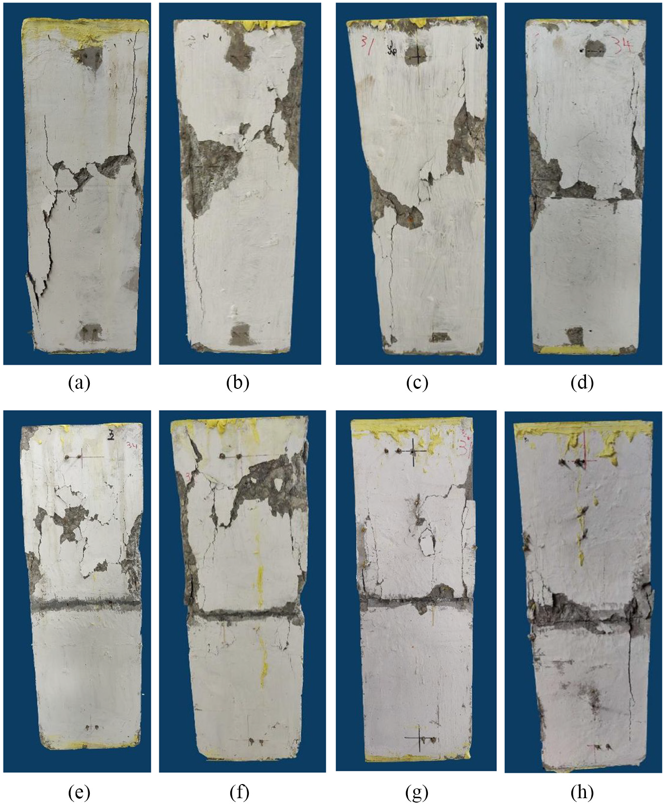
Final failure patterns: (a) C-0-0-100, (b) C-0-20-100, (c) C-0-20-50, (d) P-107-0-100, (e) P-107-20-100, (f) P-107-20-50, (g) P-71-0-100, and (h) P-71-20-100.
For a cast-in-place column, the first longitudinal crack formed in a corner when the load reached 70%–75% of the eventual peak. As the load continues to increase, the number of surface cracks increases, the cracks widen rapidly and gradually extends to the center of the column. Beyond the peak load, part of the concrete surface of column gradually spalls off. When loading was terminated, an inclined main crack has formed on the surface of the specimen. The failure modes of the three cast-in-place column specimens were relatively similar, which indicates that the addition of DCLs did not change the failure mode.
For the precast columns, when the loading increased to 60%–65% of the peak load, the first vertical crack formed at the lower corner of the upper column unit. As the load increased further the number of surface cracks gradually increased. Unlike the cast-in-place columns, the cracks which formed in the precast columns were more concentrated in the upper column unit. There were relatively fewer in the lower column unit, while the number of cracks in the upper and lower parts of the cast-in-place columns were roughly the same. This may due to the bending of the longitudinal reinforcements at the corners of the upper column unit weakening their restraining effect. Beyond peak load, surface spalling was again observed. When the loading was terminated, no typical main crack was found consistently on the surface of the precast columns, unlike with the cast-in-place columns.
Axial load-deformation curves
Figures 10, 12, and 13 show the deformation curves under axial compression. The deformation is the average of the four LVDTs’ measured values. The stiffness Kin is defined as 0.4 times a specimen’s peak load divided by the corresponding axial deformation Δ0.4 (i.e. Kin = 0.4Pmax/Δ0.4) (Wu et al., 2020). A column’s ductility coefficient μ0.85 is defined as its axial deformation at 85% of the peak load divided by the yielded deformation after the peak load (i.e. μ0.85 = Δ85%/Δy) (Lue et al., 2007). The yielded deformation was determined by extending a line connecting the origin and 75% of the peak load on the deformation curve and finding the intersection of that line with a horizontal line passing through the peak load point. The yielded deformation is defined as the intersection point’s abscissa value. ΔPmax is defined as the axial deformation at the peak load. The axial load bearing capacities Pmax, stiffnesses Kin, ductility coefficients μ0.85, and ΔPmax are listed in Table 6.

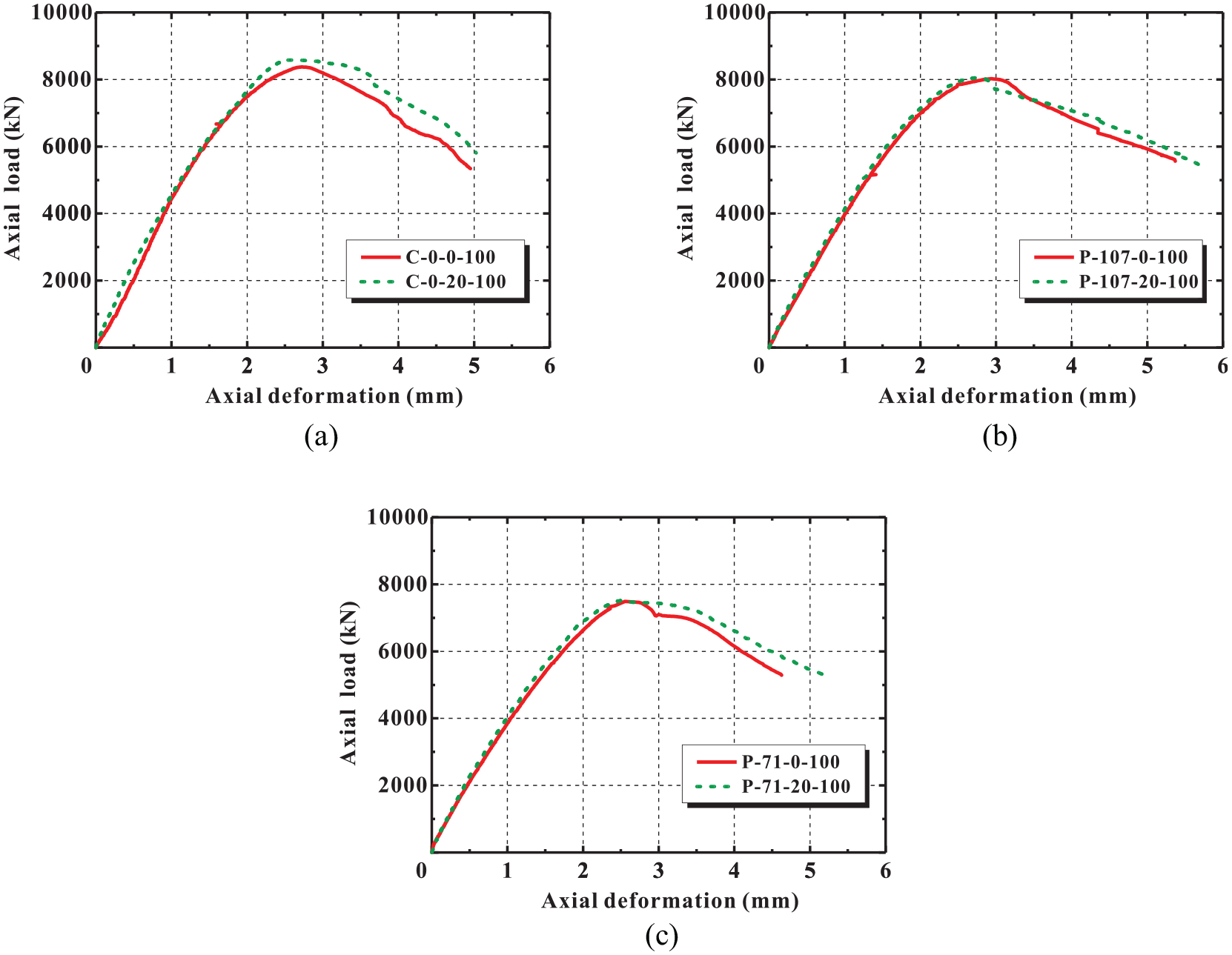
Effect of production method: (a) specimens without DCLs, (b) specimens with DCLs and 100mm transverse reinforcement spacing, and (c) specimens with DCLs and 50 mm transverse reinforcement spacing.
Experimental results.

It can be seen from Figure 10 and Table 6 that: (1) when the replacement ratio of DCLs is identical, the stiffness of a precast column with a greater degree of longitudinal reinforcement bending is 7.2%–10.7% lower than that of a cast-in-place column. This is due to the fact that the grouting in the joint is pure mortar with an elastic modulus less than that of concrete; (2) when the DCLs replacement ratio is identical, the axial load bearing capacity of a precast column (L = 107 mm) with a greater degree of bending in the longitudinal reinforcement bending 4.2%–6.2% lower than that of a cast-in-place column. With less bending (L = 71 mm) the axial load bearing capacity of a precast column is 10.6%–12.4% lower. Precast columns with little bending of their longitudinal reinforcement are weaker than those with more bending; (3) with the same DCLs replacement ratio, the ductility coefficients of cast-in-place precast columns are roughly the same.
It can be seen from Figure 11 that a distributed outward horizontal force −qc is applied on the peripheral concrete of the upper part (AO) of the reinforcement’s bent section (AB). This distributed force clearly will generate horizontal tensile stress in the peripheral concrete putting it under biaxial stress (compression in vertical direction, and tension in the horizontal direction). The vertical compressive strength of the peripheral concrete will then be lower than that under uniaxial compression. As a result, the axial load bearing capacity of the precast column will be lower than that of an equivalent cast-in-place column. For columns P-107-0-100 and P-71-0-100, the measured strains at point O (see Figure 11 and the measuring point P2 in Figure 6) were, respectively, −251.0 and −237.3 με at the peak load. The difference between the two measured strains was only 5.5%, indicating that there is little effect of the reinforcement’s degree of bending on either the internal force FO at point O or the total horizontal force acting on the peripheral concrete. In comparison with the column having more bent reinforcement (P-107-0-100), the vertical projection height of AO in the column with less bent reinforcement (P-71-0-100) was smaller (see Figure 2). When the total horizontal forces applied on the peripheral concrete of P-107-0-100 and P-71-0-100 were almost the same, the horizontal tensile stress related to P-71-0-100 was obviously larger than that pertaining to P-107-0-100. As a result, the decrease in the vertical compressive strength of the peripheral concrete in P-71-0-100 was more remarkable than that in P-107-0-100, leading to relatively lower axial load bearing capacity for P-71-0-100 with its less bent reinforcement.
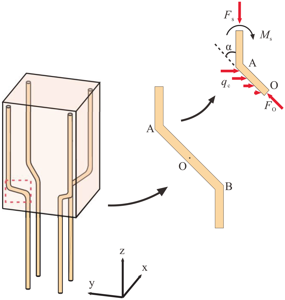
Force analysis of bending reinforcement.
It can be seen from Figure 12 and Table 6 that: (1) when the replacement ratio of DCLs increases from 0% to 20%, a column’s axial load bearing capacity increases very slightly (0.3%–2.4%). This is because the DCLs are slightly stronger than FC; (2) when the replacement ratio of DCLs is increased from 0% to 20% a column’s stiffness increases by 5.2%–9.3% and its ductility coefficients increases by 5.0%−12.6%. This indicates that the addition of DCLs will not weaken the stiffness or reduce the ductility of a column.
Effect of DCLs: (a) cast-in-place specimens, (b) precast specimens with larger bending distance, and (c) precast specimens with smaller bending distance.
Turning to Figure 13 and Table 6: (1) when stirrup spacing is reduced from 100 to 50 mm a column’s axial load bearing capacity increases slightly (1.1%–1.8%). There is slightly more transverse restraint at the bend, slightly improving the concrete’s bearing capacity in compression; (2) reducing the spacing also reduces a column’s stiffness by 1.9%–3.7%. This is because the transverse restraining effect of the stirrups is not fully exerted at 40% of the peak load, and with 50 mm stirrup spacing the 70–90 mm DCLs will be mainly concentrated within the stirrup. They are unlikely to go through the gap between adjacent stirrups to achieve relatively uniform distribution over the column’s cross-section. Since the DCLs used in these experiments were slightly stronger than the FC, the columns were slightly less stiff with the smaller stirrup spacing; (3) the spacing of the stirrups had little effect on a column’s ductility coefficient.

Effect of transverse reinforcement spacing: (a) cast-in-place specimens and (b) precast specimens with larger bending distance.
It can be seen from Table 6 that: (1) when the replacement ratio of DCLs equals to 0, the ductility coefficients of the precast column with greater degree of longitudinal reinforcement bending (L = 107 mm) and the precast column with less degree of longitudinal reinforcement bending (L = 71 mm) are, respectively, 1.5% and 3.5% lower than that of the cast-in-place column; (2) when the replacement ratio of DCLs equals to 20%, the ductility coefficients of the precast column with L = 107 mm and the precast column with L = 71 mm are 4.2% and 3.5% higher than that of the cast-in-place column, respectively; and (3) when the stirrup spacing is reduced from 100 to 50 mm, the ductility coefficient of the precast column with L = 107 mm is 4.3% higher than that of the cast-in-place column. From the above data, it is clear that the ductility of the precast column is almost the same as that of the cast-in-place column.
Figure 14 shows the ratios of joint deformation to the deformation of the entire column under axial compression. The axial deformation of a joint was measured by the strain gauges attached vertically on the surface of the grouting. The reported values are the average of the readings from eight strain gauges multiplied by the width of the joint (6 mm). It can be found from Figure 14 that: (1) the maximum value of the ratio of the grout’s axial deformation at the joint to the axial deformation of the entire column is between 0.02 and 0.06, which is significantly larger than the ratio of the width of the joint (6 mm) to the length of the area measured by the LVDTs (1000 mm). The reason for that is the grout’s relatively low elastic modulus due to the absence of coarse aggregate; (2) the ratio of the grouting’s axial deformation to that of the column increases to a maximum rapidly early in the loading, then decreases continuously with increasing axial load. This may be because the grouting is seriously compressed in the initial stage of loading.

The ratio of deformation in the grouting material to that of the entire column: (a) precast specimens with larger bending distance and (b) precast specimens with smaller bending distance.
Evaluating the axial load bearing capacity of precast columns with bent reinforcement
Table 7 compares the axial load bearing capacity calculated according to Chinese code GB 50011-2010 (2010), American code ACI 318-14 (2014), and the measured values. The calculation formula of GB 50011-2010 is

and that of ACI 318-14 is

Comparison of calculated and measured capacities of column specimens.
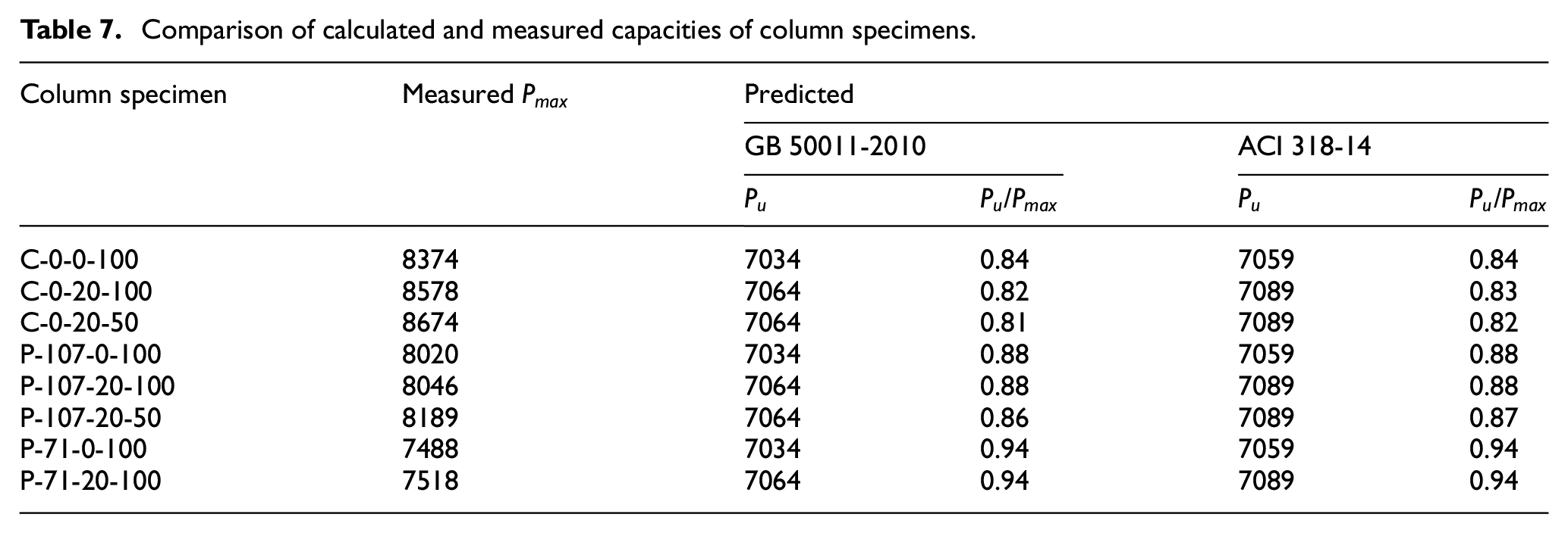
It can be found from Table 7 that: (1) the axial load bearing capacities predicted by the Chinese and American codes are close to each other. The measured values are somewhat higher; (2) to ensure that precast and cast-in-place columns are designed with the same level of security, their
Conclusions
Axial compression tests were carried out on two-part precast columns containing RLC concrete. The failure mode, axial load bearing capacity, stiffness, and ductility of the precast column segments, as well as the axial deformation of the grout between the upper and lower halves of the columns were investigated. They were compared with the values for cast-in-place columns. The results support the following conclusions:
(1) The failure mode of cast-in-place concrete columns is different from that of precast columns. The surface cracks on cast-in-place columns are distributed more evenly, with an inclined main crack forming on the surface. The surface cracks on precast columns are mainly on the upper half, and there is no typical inclined main crack.
(2) When the strength of the waste concrete is close to that of the FC, incorporating DCLs have no significant effect on a column’s performance whether precast or cast-in-place. A column’s axial load bearing capacity, stiffness, and ductility are not reduced by incorporating DCLs.
(3) Due to the bends in the longitudinal reinforcement, the axial load bearing capacity of a precast concrete column is 4.2%–12.3% lower than that of a similar cast-in-place column. However, the axial load bearing capacity of precast concrete columns increases with the degree of bending in the longitudinal reinforcement increasing from L=71–107 mm.
(4) Decreasing the stirrup spacing has little impact on a precast column’s axial load bearing capacity and ductility.
(5) In order to ensure that the designed axial load bearing capacity of a precast concrete column has a safety margin similar to that of a cast-in-place column, the predicted value should be multiplied by 0.85 if there is little bending in the reinforcement (L=71 mm) or 0.95 if the bending is greater (L=107 mm).
Considering that the mechanical properties of the epoxy resin used to anchor the bent reinforcement deteriorate quickly with increasing temperature, and considering that the shear capacity of the joint between the upper and lower halves of the column is mainly provided by the bent reinforcement, the fire resistance, and shear behavior of the newly-proposed precast RLC columns need to be investigated carefully. Experimental studies on these two issues are being conducted by the authors’ research team, and some other shear-resistant configurations are being tested.
Footnotes
Declaration of conflicting interests
The author(s) declared no potential conflicts of interest with respect to the research, authorship, and/or publication of this article.
Funding
The author(s) disclosed receipt of the following financial support for the research, authorship, and/or publication of this article: The research reported was financially supported by the Key-Area Research and Development Program of Guangdong Province (2019B111107003), the National Natural Science Foundation of China (52078219), and the Guangdong Provincial Key Laboratory of Modern Civil Engineering Technology (2021B1212040003). The financial supports are highly appreciated.