
Abstract
This study introduces a shape memory alloy (SMA)-spring damper which is composed of SMA bars and elastic springs arranged in perpendicular. The damper depicts a curved flag-shape hysteretic behavior that is endowed with self-centering capacities and large deformation capabilities but uses reduced amount of SMA material. A design procedure is proposed to apply the SMA-spring damper to the bridge with laminated rubber bearings which would slide under seismic excitations. Analytical results validate the effectiveness of SMA-spring dampers in seismic control of the bridge: (1) The damper provides trivial stiffness to the bridge at small displacement, and the isolation efficiency of the bridge is maintained; (2) large horizontal force is provided for the structures at large deformation of the bearings, which alleviates the excessive displacement of bearings and prevents span collapse; and (3) the damper helps recenter the bearings and reduce the residual displacement of the bridge.
Keywords
Introduction
Passive vibration control for seismic applications has been widely applied in structure and infrastructure engineering since 1990s. The principal function of a passive vibration control device is to dissipate the input seismic energy and suffer from the most damage to protect the major structural elements. The energy dissipation mechanisms of these conventional devices include the yielding process of metals, friction mechanisms, viscous fluids, and viscoelastic materials (Parulekar and Reddy, 2009). Despite the effectiveness of these devices for seismic control, they are found less effective for controlling residual deformation, which might render the structures unusable or irreparable after the earthquake (Macrae and Kawashima, 1997). In light of this, there has been a trend to apply self-centering (SC) dampers for seismic reduction of post-event residual deformations of structures.
Several strategies have been applied for the SC properties, including unbonded post-tensioned (pre-stressed) bars, special energy dissipating dampers (Zhu and Zhang, 2008; Chou and Chen, 2011), or special material. Among these, shape memory alloys (SMAs) have been a popular solution for the construction of SC capabilities for civil engineering applications. This type of material is famous for its inherent super elasticity and shape memory effect that favorably endows the structure with recentering capability (Graesser and Cozzarelli, 1991; Li et al., 2018b; Miller et al., 2012; Zheng et al., 2018). So far, SMAs have been used in a variety of applications including SMA-based devices, SMA bracing systems, SMA beam–column connectors, SMA-based isolation devices, SMA-based retrofitting devices, SMA restrainers, and so forth (Ozbulut et al., 2011). The effectiveness of these devices has been widely exploited in the design, construction, and retrofit of civil engineering systems for the vibration control of structures (Casciati et al., 2009; Cardone et al., 2006; Dolce et al., 2000, 2005; Fang et al., 2019; Hedayati Dezfuli and Alam, 2018; Humbeeck and Kustov, 2005; Khan et al., 2004; Miller et al., 2012; Motahari et al., 2007; Shinozuka et al., 2015; Williams et al., 2002; Zheng et al., 2021).
However, difficulties have been found in applying SMA-based devices to structures expected to undergo large seismic displacement. For instance, several studies have used SMA wires wrapped around isolation bearings to improve the recentering capability of bearings (Cao et al., 2020; Choi et al., 2006; Hedayati Dezfuli and Alam, 2014; Mishra et al., 2016; Shinozuka et al., 2015; Zheng et al., 2019). In some studies, the SMAs would not be functional at very large shear deformation of the bearings (200%) as the SMA wires will experience more than 20% axial strain (Choi et al., 2005). In some other studies, a cross configuration is used to substitute the straight configuration to enable the SMA wires to accommodate the large shear deformation of the bearings (Hedayati Dezfuli and Alam, 2013, 2015). However, a much greater length of SMA wire is required for the cross configuration compared to the straight arrangement. Given the fact that the high cost of SMA material has impeded the actual implementation of SMAs in civil structures where large quantity of material is required (Ozbulut et al., 2011; Desroches and Smith, 2004), too much usage of SMA material makes the application to practical engineering even more unrealistic. There is an urgent need of the SMA-based device that is able to accommodate the large displacement of the structures while uses the reduced amount of SMA material.
This study introduces a new SMA-spring damper that is endowed with SC capacities and large deformation capabilities. The proposed damper consists of SMA bars and elastic springs arranged in perpendicular and they are able to deform in series to sustain large deformation. Based on a special force transition mechanism, the SMA bars are always elongated under tension or compression force to save the usage of SMA material. The mechanical properties of the damper are illustrated, which depicts a curved flag-shape hysteretic behavior. The SMA-spring dampers are then applied to bridges with laminated rubber bearings following a proposed design procedure. The effectiveness of the damper in seismic control of the bridge is evaluated and outlined.
SMA-spring damper
Arrangement of the damper
The damper consists of three systems: the SMA system (I), the spring system (II), and the restrainer system (III), as shown in Figure 1. Different systems are assigned with different colors. To describe the damper, all the subassemblies are listed from 1 to 11: 1—top force transmission steel plate; 2—the top anchorage block for SMA bar; 3—top restrainer block; 4—top springs; 5—top mounting block; 6—SMA bar with threaded ends; 7—bottom mount block for springs; 8—bottom springs; 9—bottom restrainer block; 10—the bottom anchorage block for SMA bar; and 11—bottom force transmission steel plate. The components within the same system are either connected through bolting or welding, whereas they are detached between different systems. Schematic view of the shape memory alloy-spring damper.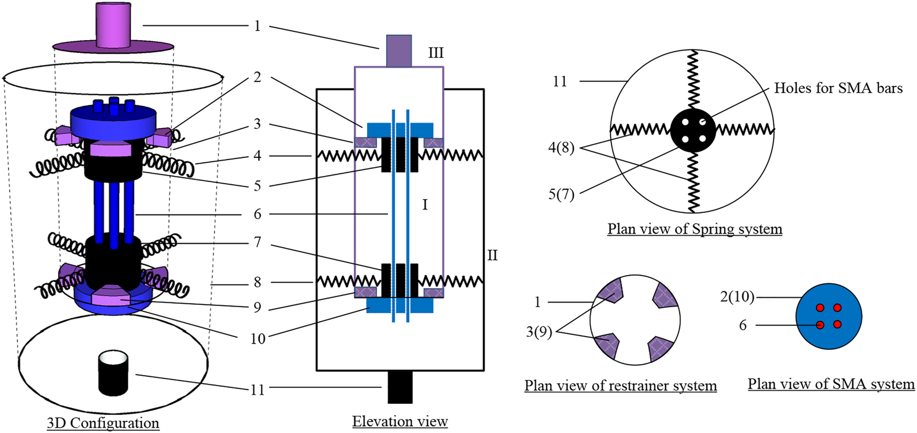
The working principle of the SMA-spring damper is described in Figure 2. For illustration, it also depicts the transmission path of the tension or compression force through the arrows. Upon tension, as shown in Figure 2(b), the tension force of 1—top force transmission steel plate is transmitted to the 2—top anchorage block, which results in the tension of the 6—SMA bars. The tension force of SMA bars causes the upward movement of the 10—bottom anchorage block together with the 9—bottom restrainer block which deforms the bottom springs. The vertical force components of springs are then transmitted to the bottom force transmission steel plate. Note that the 4—top springs, 5—top mounting block, and 9—bottom restrainer block have no interaction with the resistance of the device upon tension. Upon compression, the force transmission path is that 1—top force transmission steel plate, 9—bottom restrainer block, 10—bottom anchorage block, 6—SMA bars, 2—top anchorage block, 5—top mounting block, 4—top springs, and 11—bottom force transmission steel plate. Similarly, the 8—bottom springs, 9—bottom mounting block, and 3—top restrainer block do not work for compression resistance. Response of the shape memory alloy-spring damper subjected to tension force and compression force.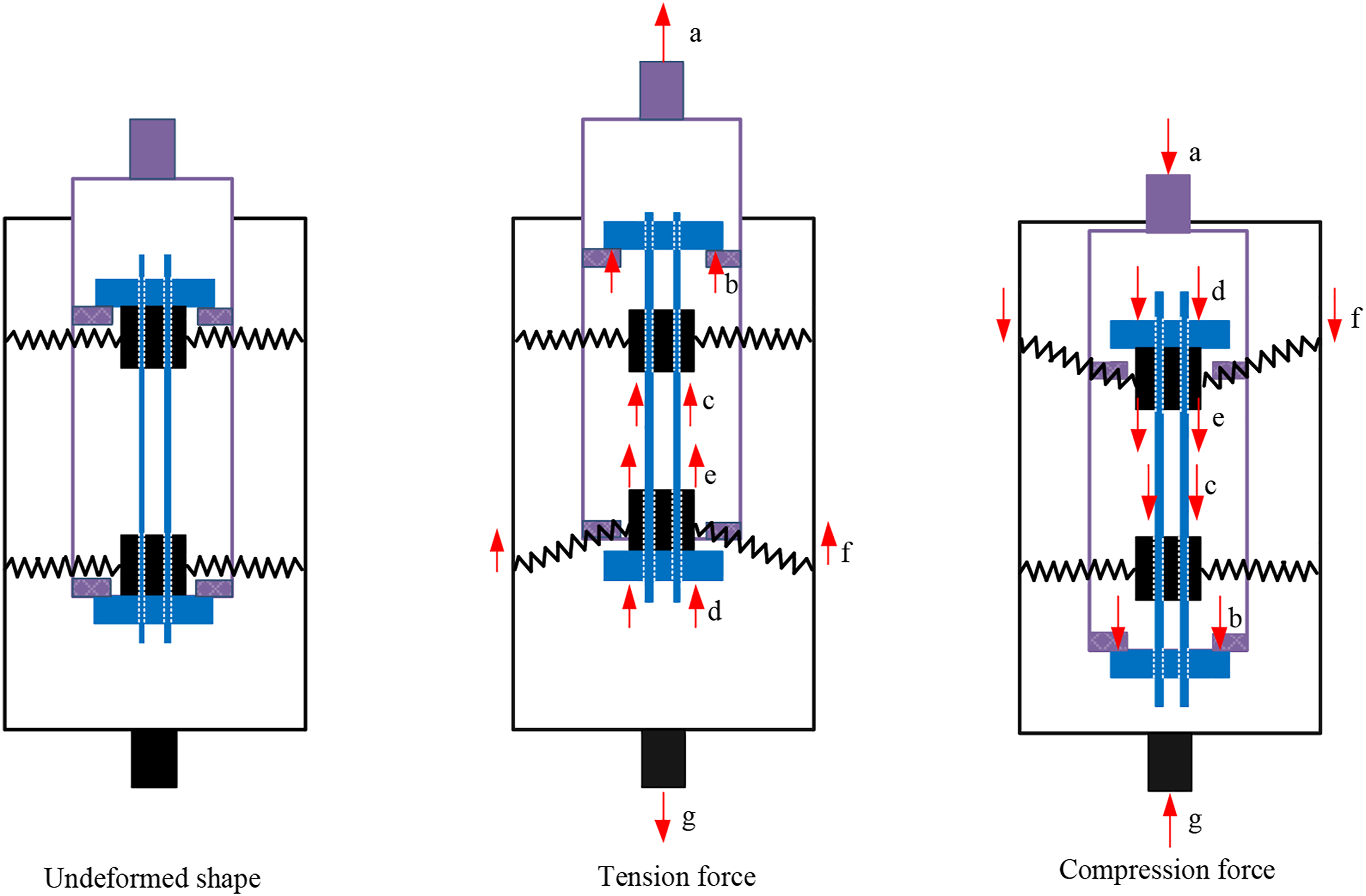
Above discussion indicates two key features of the proposed SMA-spring damper. First, the SMA bars and springs deform in series subjected to external force, which enables the damper to undergo large deformation. This is very useful for seismic control of structures expected to develop significant displacement, like bridge isolation bearings. Meanwhile, the SMA bars are always elongated when the damper is deformed. This, on one hand, avoids the buckling-induced instability problem of SMA bars, while, on the other hand, fully utilizes the SMA bars so that reduced SMA material is needed. As a result, the proposed SMA-spring damper is suitable for engineering implications, especially useful for controlling large displacement.
Mechanical properties of the damper
The mechanical behaviors of the device depend on the design parameters of SMA bars and the springs. SMA bars
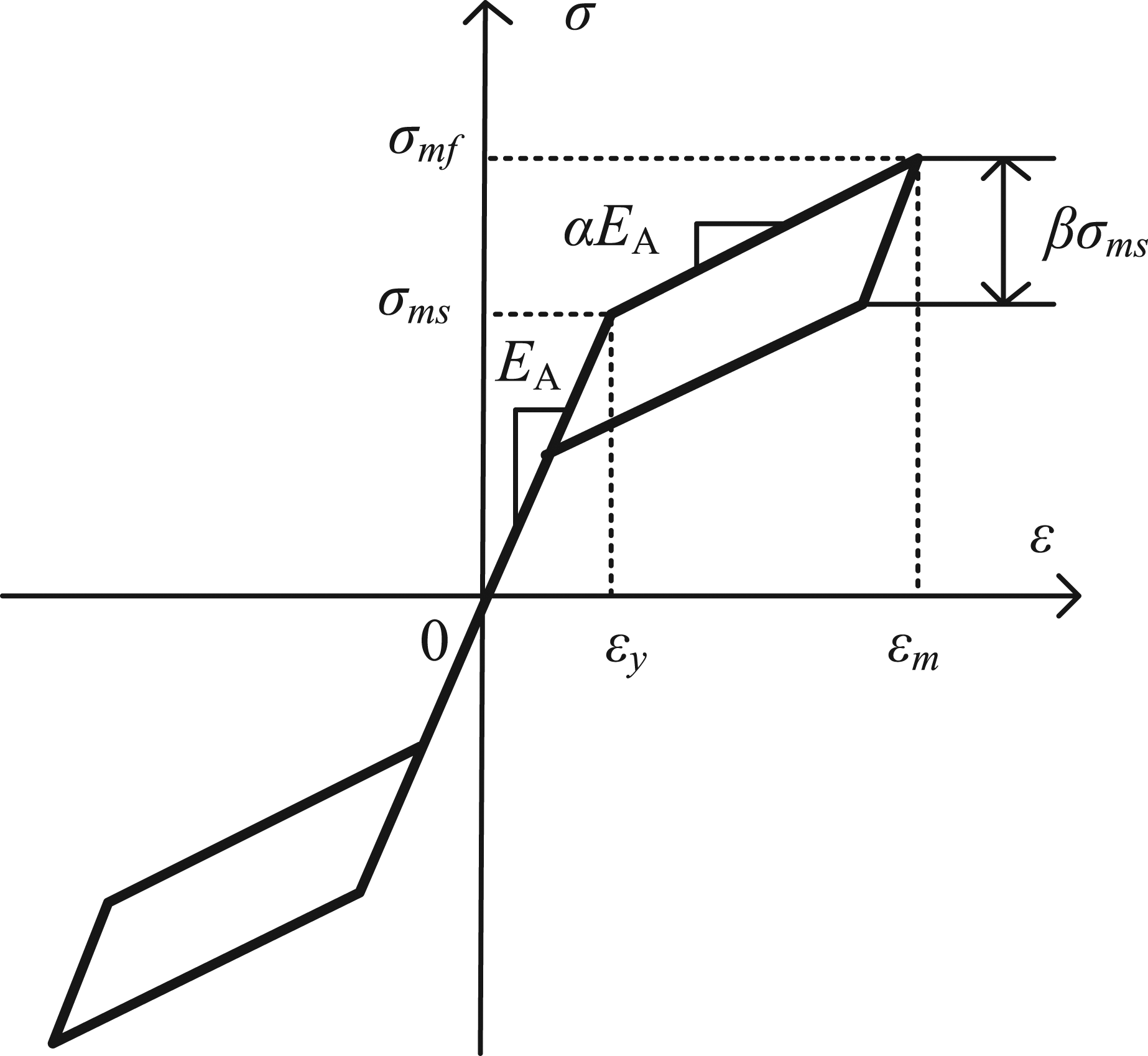
For SMA bars, the force versus the deformation can be simplified as linear piecewise flag-shape model (Figure 3) expressed numerically in equation (1)
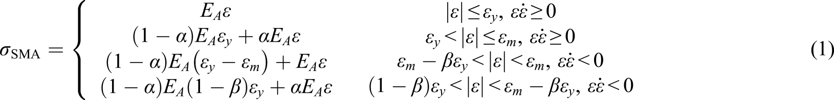
Where 2. Springs Stress–strain model of the shape memory alloy bars.


Under a deformation of y (Figure 4), the springs are displaced from its horizontal position to an inclined position. Several studies (Antoniadis et al., 2015; Attary et al., 2015; Li et al., 2018a; Pasala et al., 2013) have precompressed the springs which results in the negative stiffness negative, termed as “negative stiffness damper,” for seismic control of structures. The feasibility and reliability of such springs have been verified both numerically and experimentally. In this study, instead of being precompressed, the springs are either pretensioned or unprestressed. This guarantees that the damper always sustains tension force to avoid buckling of the SMA bars. Suppose the tension force is Force–deformation relationship of springs.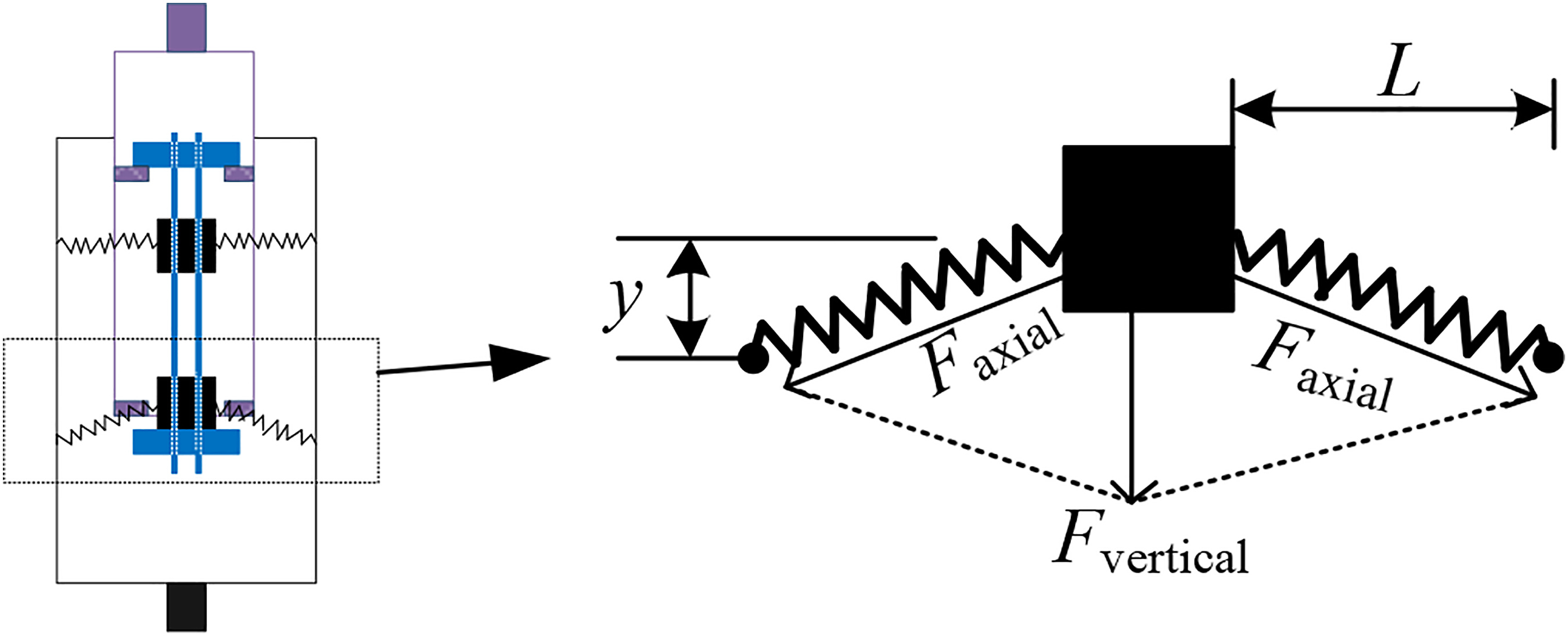

which yields

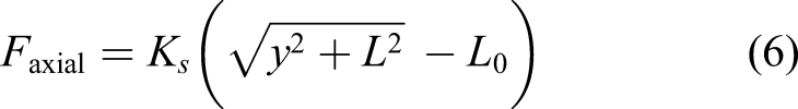
The axial force of the springs is determined based on Hooke’s law
The vertical component of the force is

The output force of n springs and the output stiffness are

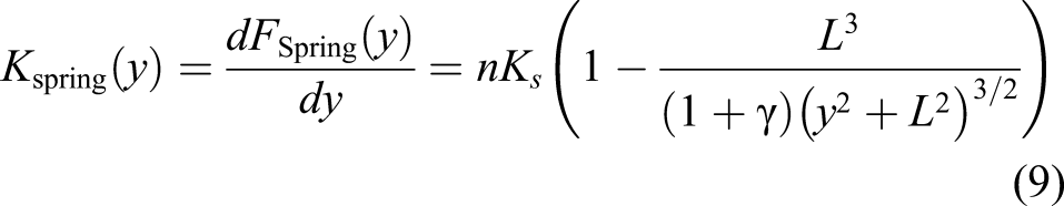
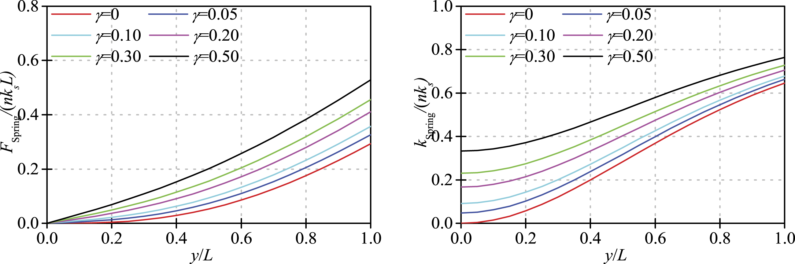
Figure 5 shows the normalized output force and stiffness of the springs subjected to the deformations for different pretension ratios of 3. Total response of SMA-spring damper Normalized force and stiffness of the springs with its deformation.
Since the SMA bars and springs are arranged in series, the output force is Total response of the shape memory alloy-spring damper.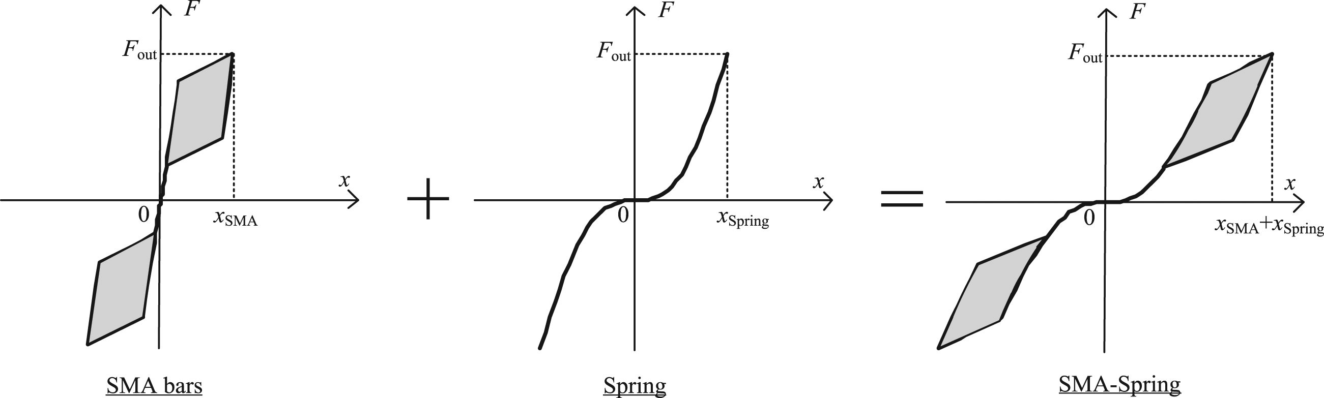
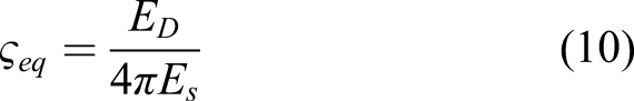
It should be noted that since the spring stays in the elastic range during the excitation, the total energy dissipation originates mainly from the SMA bars. Generally, the equivalent viscous damping ratio
Applying SMA-spring damper to bridges with laminated bearings in China
Bridge description and modeling
Due to the low cost and good reliability, laminated rubber bearings are widely used for highway bridges in China. These bearings provide sound stiffness in the vertical directions while relies on the friction force between the bearing pads and the girder to resist the horizontal force from the superstructure (Xiang and Li, 2017). As a result, these bearings tended to slide under seismic loadings in the horizontal directions. The sliding behavior of the bearings limits the forces transferred between the superstructure and substructure, which are protected to maintain essentially elastic seismic behavior. However, without restraint after bearing sliding, the superstructure would undergo extreme horizontal displacement and have large residual displacement. Wenchuan earthquakes in 2008 revealed that the typical damage feature of this type of bridge is directly associated with the large superstructure displacement, including the failure of shear key, destruction of expansion joints and abutment, and even span collapse, whereas the piers are seldom damaged, as shown in Figure 7 (Han et al., 2009; Li et al., 2008). To this end, SMA-spring damper is introduced to control the large superstructure displacement and the residual displacement for bridges with laminated rubber bearings. Typical seismic damages of bridges with laminated rubber bearings (images by Xiang and Li (Xiang and Li, 2016) with permission). (a) Sliding of the bearings, (b) failure of the shear keys, (c) destruction of the abutments, and (d) span collapse.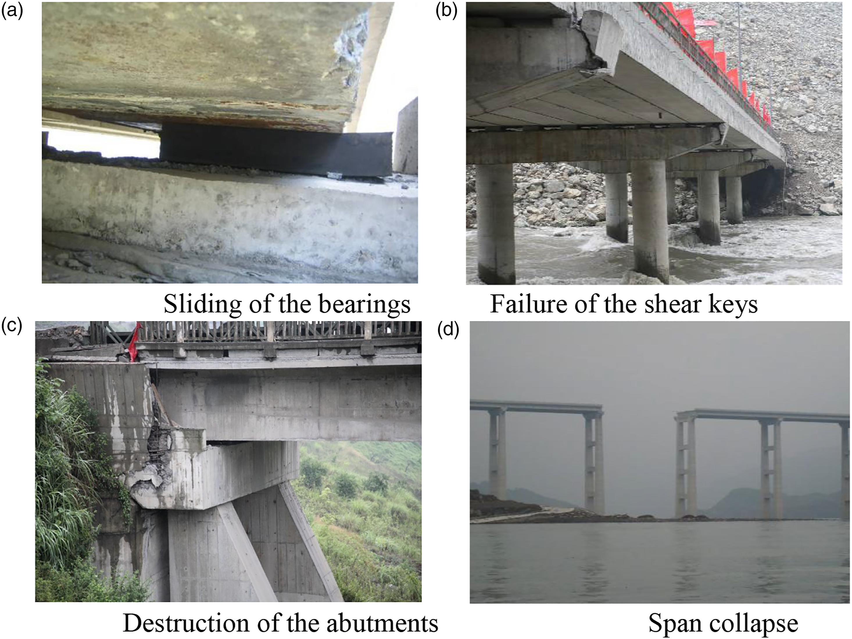
A typical simply supported girder bridge is used for seismic evaluation, as shown in Figure 8. The span length is 25 m, which is composed by pre-stressed precast T-girders with a height of 1.75 m. The total mass of one span is approximately 300t. The substructure is cylindrical concrete column with a height of 10 m and a diameter of 1.5 m. The longitudinal reinforcement ratio is 2.0%. The laminated rubber bearings are placed directly on the bent cap and support the superstructure through steel plate which are mounted to the superstructure. There are no horizontal restraints between the bearings and the bend cap or steel plate. The bearings are formed into the circular shape with a diameter of 400 mm and a height of 84 mm. Transverse concrete shear keys are installed at two sides of the bent cap to prevent the transverse deformation of the bearings. In the longitudinal direction, however, there are no restraints between the superstructure and the substructure other than the friction force between the bearings and the steel plate. For this end, the SMA-spring damper is installed in the longitudinal direction of the bridge to control the large superstructure displacement. A detailed description is illustrated in Figure 8 for the connections of the SMA-spring damper to the deck and the bent cap. Description of the bridge (unit: cm).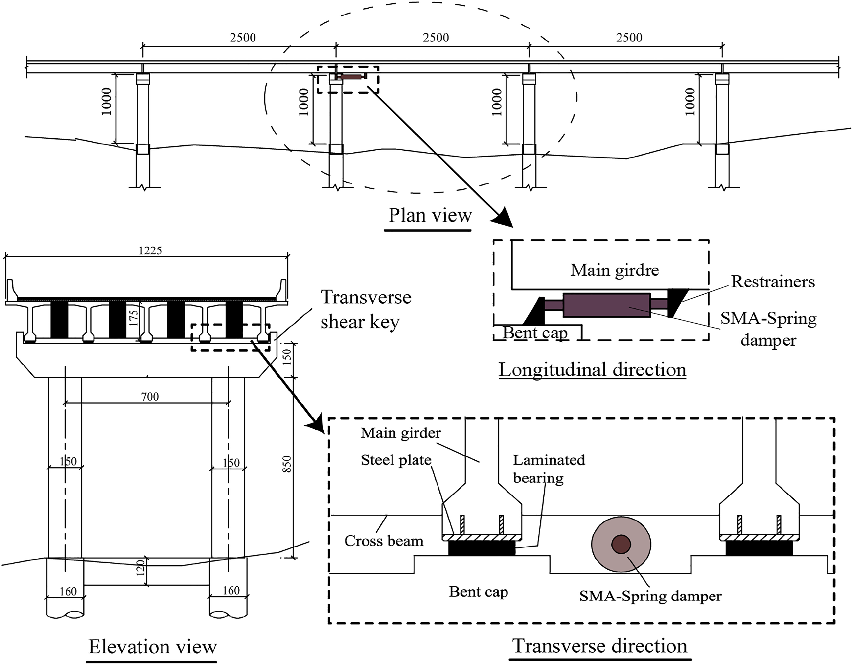
The Open System for Earthquake Engineering Simulation (OpenSees) was employed to model the bridge system controlled by SMA-spring damper. For simplicity, the prototype bridge was represented by a single mass-column system as shown in Figure 9. Due to the symmetric arrangement of the bridge, only half of the bridge is modeled. The superstructure is represented by a node assigned with a nodal mass. To represent the distribution of the material nonlinearity along the length of the piers, the fiber-modeling approach is implemented which discretizes the pier section into unidirectional confined concrete, unconfined concrete, and steel fiber. Menegotto-Pinto steel model with isotropic strain hardening property is used for modeling the reinforcing steel material (Carreño et al., 2020). For the unconfined and confined concrete, the uniaxial Kent–Scott–Park model (Kent and Park, 1971) with degraded linear unloading/reloading stiffness, is employed to describe the nonlinear behavior of concrete. Since the bridge Modeling of the bridge.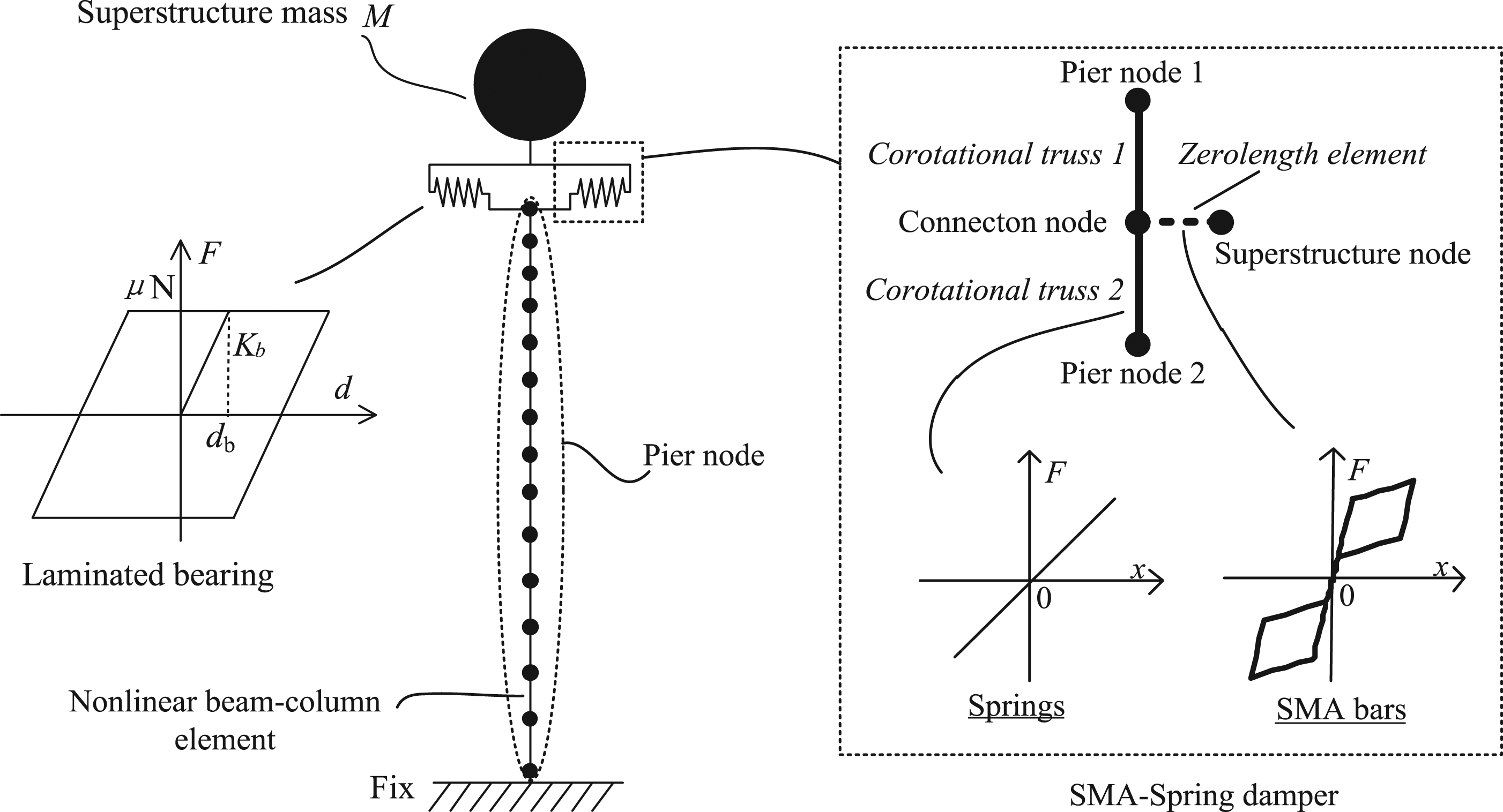
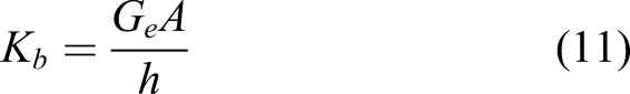
The seismic sliding behavior of bearings was modeled using an initial elastic stiffness before sliding and a constant friction after sliding. The effective initial shear stiffness (K
b
) and the sliding displacement (d
b
) are calculated by equations (11) and (12)

To represent the realistic behavior of the SMA-spring damper, the springs and the SMA bars are separately modeled. The springs are modeled employing corotational truss element which has the exact length of the springs and is applied with an elastic behavior. The corotational truss element has a set of corotational axis that rotate with the element, thus taking into account the exact geometric deformation of the element. The SMA bars are modeled using the “zerolength” element with the material depicts the flag-shape behavior.
Design of SMA-spring damper
To restrain the large superstructure displacement of the bridges with laminated bearings, SMA-spring damper is implemented between the interface of the superstructure and the substructure. The concept of applying SMA-spring damper is that the bearings are protected from excessive deformation and residual deformation, while the superstructure and substructure remains in the essentially elastic range, which is achieved based on the curved flag-shape hysteretic behavior of the SMA bars. To this end, it is of significance to determine the design parameters of SMA-spring damper to fulfill the design concept. A design procedure is proposed as shown in Figure 9, and detailed description is illustrated as follows: Seismic requirements
Seismic requirements of SMA-spring damper are the allowable deformation Ds and the maximum force Fs. The former is set to be the allowable bearing deformation so that span unseating is prevented. Considering the bearing height of 84 mm, the allowable deformation of the damper is set to be Ds = 168 mm, corresponding to the 200% of the bearing height. The latter is set so that the substructure remains in the essentially elastic range under seismic actions. Based on sectional analysis, the yield moment of the section, corresponding to the first yield of the longitudinal reinforcement, is My = 5600 kN m. Since it generally gives satisfactory results for regular isolated bridges to ignore the contribution of the pier mass, the allowable shear force of the pier section is Fc = My/H = 5600 kN m/10 m = 560 kN. On the other hand, the maximum bearing friction force is Fb = μN = 0.2 × 1500 kN = 300 kN. It is anticipated that bearing sliding occurs prior to the yielding of the substructure. The maximum shear force provided by the SMA-spring damper is Fs = Fc−Fb = 560 kN−300 kN = 260 kN. 2. SMA material
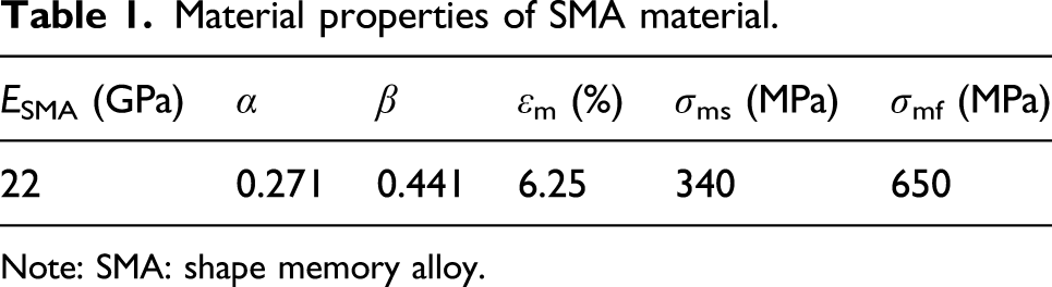
Various types of SMA material can be sourced from previous literatures, including nickel–titanium, Cu-based shape memory alloys, and ferrous shape memory alloys, as summarized by Defile and Alam (Hedayati Dezfuli and Alam, 2013). The typical design parameters of SMA material used in this study is listed in Table 1. These parameters are extracted from Qiu et al. (Qiu et al., 2020) based on tensile results of the SMA coupons. 3. Some assumptions Material properties of SMA material. Note: SMA: shape memory alloy.
The force–displacement output of the SMA-spring damper depends on several parameters, including the SMA bar length LSMA, the spring length Lspring, the pretension ratio γ, the area of the SMA bars ASMA, and the stiffness of the springs Kspring. The following three parameters, LSMA, Lspring, and γ are first determined based on the work space restrictions at the bearings for anchorage.
First, the length of the spring is determined. Accounting for the vertical gap (0.5 m) between the superstructure and the substructure, the length of the spring is assumed Lspring = 0.2 m, which is slightly less than half of the vertical gap. The remaining space, equal to 0.5 m−2 × 0.2 m = 0.1 m, is suitable for installation of the damper.
If the SMA cables are simply used to undergo the allowable deformation of the bridge, the length of the cable would be LSMA = Ds/εm = 0.168 m/6.25% = 2.688 m. To accommodate the reverse movement of the bearings, two cables arranged in opposite directions are required and the total length is 5.376 m. To reduce the SMA material used, the length of the SMA bars is set to be LSMA = 1 m, which is 81% reduction of the SMA cables. In this way, the contribution of SMA bars to the total deformation of the damper is 1 m × 0.0625 = 62.5 mm, so the rest contribution from the springs is 168–62.5 = 105.2 mm. The design details of the SMA-spring damper, such as the dimensions, the length of the SMA, and springs, are illustrated in Figure 10. Design procedure of applying shape memory alloy-spring damper to the bridge with laminated bearings and results.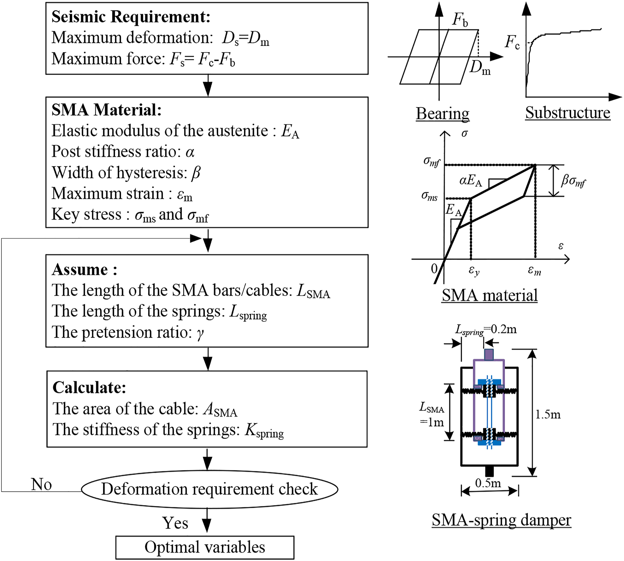
Despite the springs can be pretensioned to yield larger stiffness (see Figure 5) at small deformation of the bearing, this will introduce extra stiffness to the bridge system and reduce the isolation efficiency of the laminated rubber bearings. Meanwhile, the pretension might be difficult to conduct within the limited work space. Accounting for this, the springs are unpretensioned (γ = 0) in this application. 4. Calculation
Based on above assumptions, the area of the SMA bars is determined as ASMA = 260 kN/650 MPa = 400 mm2. In practical engineering, 8 SMA bars with the diameter of 8 mm are used instead. Based on equation (8), the total stiffness of the spring is determined to be nKs = 2145 kN/m. Accounting for eight springs arranged in each of eight dampers, the stiffness for a single spring is 33.6 kN/m. Following the design procedures of extension springs (Walsh, 2000), the springs can then be designed based on the available parameters above. Note that the deformation capacity of the spring is checked to satisfy the requirement (which is 105.2 mm in this case) so that the spring keeps in the elastic range during the earthquake.
Based on above parameters, the SMA-spring damper can be manufactured and installed to the bridge. The numerical model is then constructed using these parameters for nonlinear time history analysis of the bridge. The feasibility of the damper is validated through the comparison of the seismic responses of the bridge with and without the SMA-spring damper in the following section.
Seismic response of the bridge with SMA-spring damper
Input ground motions
Information of selected ground motions.
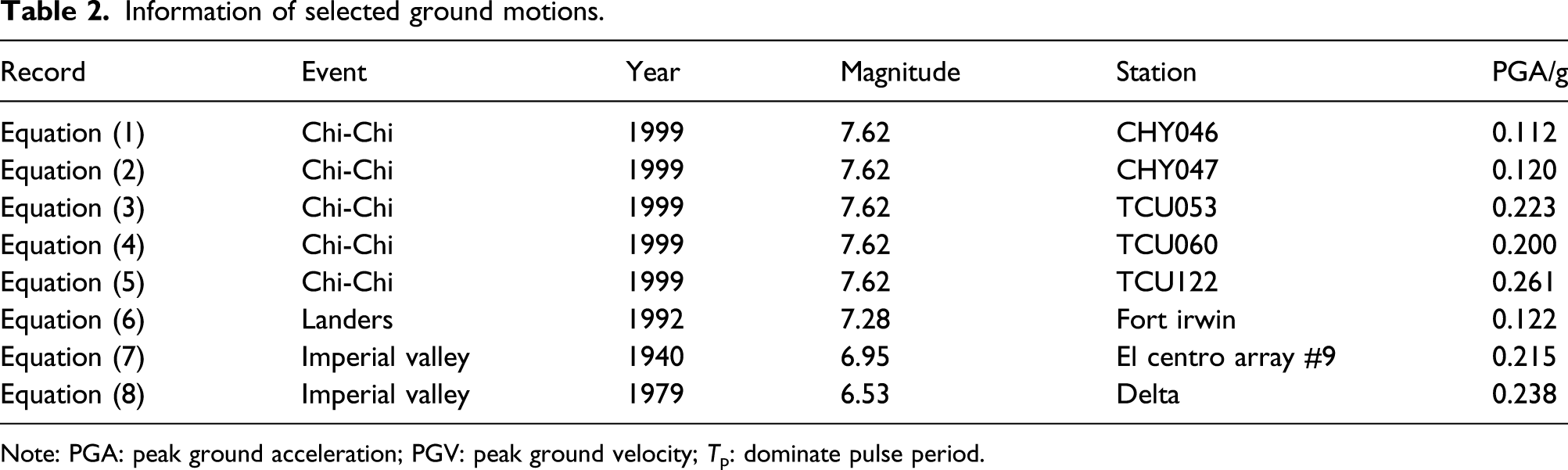
Note: PGA: peak ground acceleration; PGV: peak ground velocity; Tp: dominate pulse period.
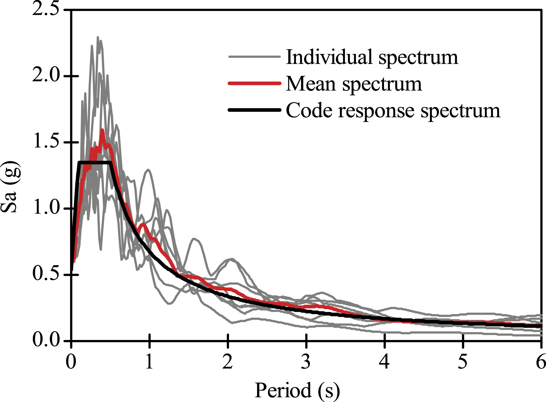
Response spectrum of selected ground motions (5% damping).
Seismic responses
The seismic performance and responses of the bridge are compared in the cases of regular bridge (termed as “regular” bridge where only laminated rubber bearings are utilized) and the bridge with SMA-spring dampers (termed as “SMA-spring” bridge where both the laminated rubber bearings and SMA-spring dampers are used). Four key responses are used for assessing the seismic performance of the bridge, namely, the maximum bearing deformation, the residual bearing deformation, the maximum bending moment of the pier bottom, and the maximum shear force of pier bottom. Note that the bearing deformation defined in this study refers to the relative displacement between the superstructure and the pier top. whereas the residual response is determined from the absolute stable values of the time history of the bearing lateral deformation at the last 5 s. Figure 12 compares the maximum responses of the bridge for two bridge systems as well as the average responses of eight ground motions and the standard deviations. Seismic responses of the bridge with and without shape memory alloy-spring dampers: (a) maximum bearing deformation, (b) residual bearing deformation, (c) maximum bending moment of pier bottom, and (d) maximum shear force of pier bottom.
It is observed from Figure 12(a) that the regular bridge system would suffer from excessive bearing deformation, ranging from 0.161 m to 0.441 m. The average value reaches 0.263 m, approximately 57% more than the design limit (0.168 m). This indicates the great chance of the span
The more obvious reduction effect for bearing residual deformation in SMA-spring bridge is observed in Figure 12(b). The reduction effect ranges from 65% to 97% with an average value of 81%. This owes much to the flag-shape hysteretic behavior of SMA-spring damper, which endows the system with SC capacities. The standard deviation is also significantly reduced, from 0.061 m to 0.023 m.
From Figures 12(a) and (b), it is concluded that the SMA-spring damper provides effective yet reliable control of bearing displacement and residual displacement for bridge with laminate bearings. The physical reason can be explained as
Figures 12(c) and (d) indicates that the introduction of SMA-spring damper will expand the seismic demands of bending moment and shear force at the pier bottom. This is unavoidable, given the extra shear force transmitted by the SMA-spring damper other than the laminated rubber bearings. The largest increases of bending moment and shear force are 13% and 25%, respectively, and the average increases are 7% and 12%, respectively. The standard deviations are not pronounced affected for bending moment and shear force. The increase of the bending moment is acceptable since the pier is kept within the elastic range, that is, the bending moment is below the yield moment 5600 kN m. Nevertheless, the increase of the shear force would be of a concern, which requires further check, especially for the bridge foundations.
For illustrations of the observations from Figure 12, Figure 13 shows the sample time history responses of the bridge with and without SMA-spring dampers under Wave No. 1. It is demonstrated that the regular bridge and SMA-spring bridge share the similar responses at the beginning of the seismic excitation when the deformation of the bearings keeps at the low level. Under this condition, the force and stiffness of SMA-spring damper are insignificant comparing to the laminated bearings so that it would negligibly interact with the dynamic responses of the bridge. After the bearing deformation reaches certain deformation (which is 0.12 m under Wave No. 1), bearing responses of two systems begin to divert from each other. For the regular system where the laminated bearings have zero stiffness after sliding, the bearings can develop significant deformation and will vacillate at a new position (which is around −0.1 m for Wave No. 1) instead of the original position. Benefitting from the enhanced spring force and the flag-shape effect of the damper, the bearing deformation of SMA-spring system is well controlled and would return to the original position during the excitation. Figure 13(b) shows that after the implementation of SMA-spring damper, the seismic responses of the bending moment are not intensively affected. This agrees well with the observations of Figure 12(c). Time history responses of the bridge with and without shape memory alloy-spring dampers under Wave No. 1: (a) bearing deformation and (b) bending moment at the pier bottom.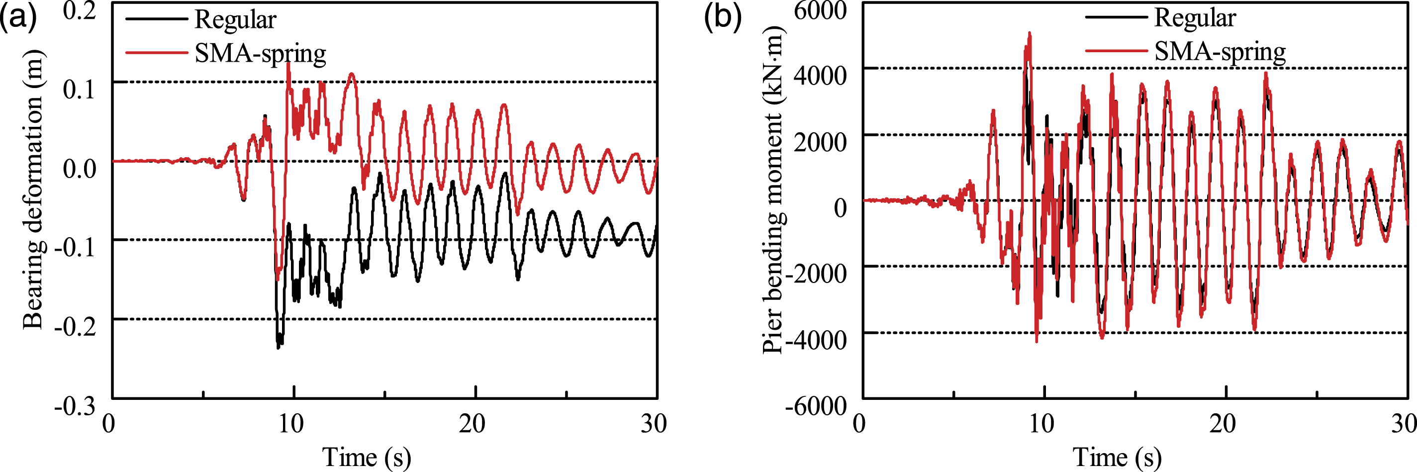
Figure 14 depicts the hysteretic responses of the bridge with and without SMA-spring dampers under Wave No. 1. Figure 14(a) shows that the implementation of SMA-spring damper significantly changes the hysteretic responses of the bearings. However, the total energy dissipation by the sliding behavior is not significantly altered. This indicates that SMA-spring damper alters the position of hysteretic behavior of the laminated bearings but would slightly affect the bearing hysteretic energy dissipation. Figure 14(b) shows the output force versus the deformation of the damper. It is noted that despite the SMA bars always sustain the tension force during the excitation, due to the special design of the damper, the output force would be either tension or compression. Figure 14(b) clearly captures the desirable hysteretic behavior of the SMA-spring damper during the seismic excitation, that is, the enhancing force–deformation relationship and the curved flag-shape hysteretic behavior. Some amount of energy is also dissipated by the damper during the excitation, from the hysteretic response of the SMA bars. However, as compared to the total energy dissipated by the laminated bearings, the SMA bars only increases 2.2% energy dissipation of the bridge system. This demonstrates that it is the additional force provided by the damper other than the increased energy dissipation that contributes most to the reduction of the bearing deformation. Hysteretic responses of the bridge with and without SMA-spring dampers under Wave No. 1. (a) Sliding of laminated rubber bearing and (b) SMA-spring damper. Note: SMA: shape memory alloy.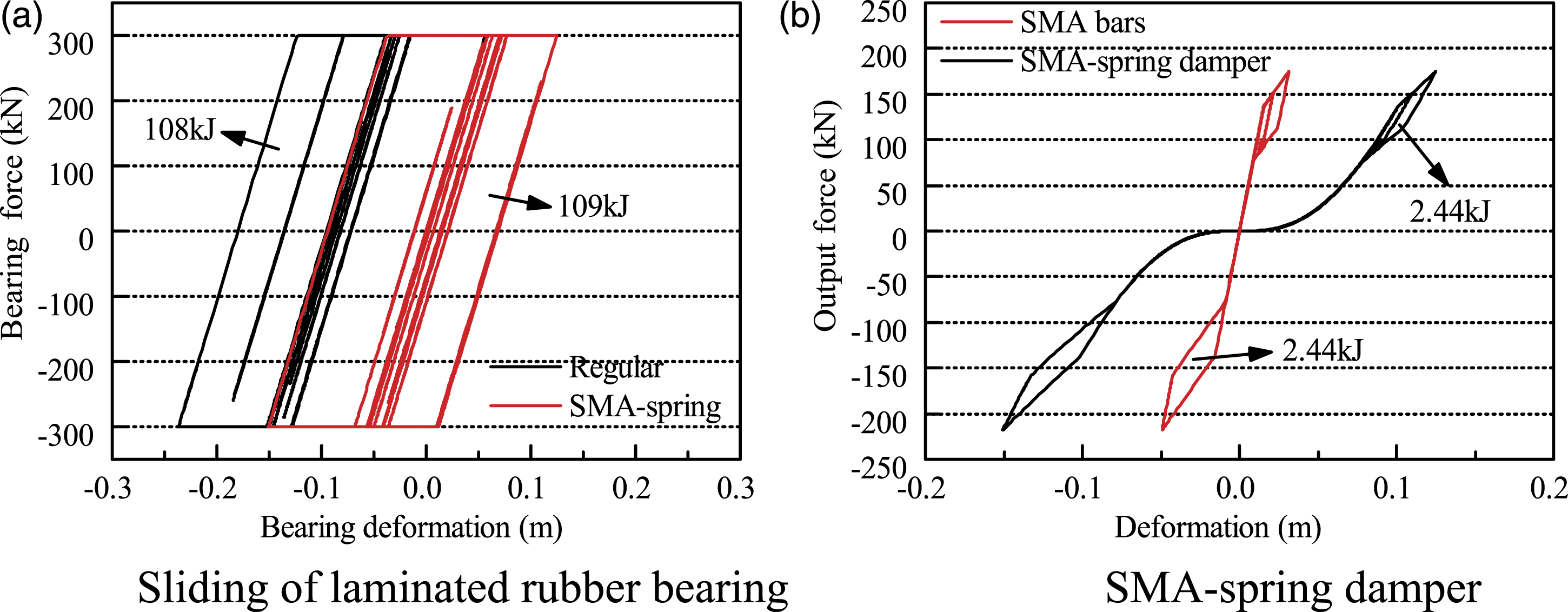
Conclusion
This study introduces a new SMA-spring damper that is composed of SMA bars and elastic springs in perpendicular. Based on a special force transition mechanism, the SMA bars always sustain tension force so as to prevent the buckling of the bars and effectively reduce the material use of SMA bars. When subjected to an external force, the SMA bars and the springs deform in series to enable the damper to undergo large deformation. Mechanical properties of the damper depict a “curved” flag-shape hysteretic behavior and the SC capability of the device. A design procedure is proposed to apply the SMA-spring damper to the bridge with laminated rubber bearings which would slide under seismic excitations. Analytical results reveal that: The bridge with SMA-spring damper shows the similar responses to the regular bridge at small displacement of the bearings so that the isolation efficiency of the bridge is maintained; The SMA-spring damper provides enhancing stiffness to the structure with the increase of bearing deformation, which provides a large horizontal force to the structures at large deformations to prevent the excessive displacement of bearings and span collapse. Meanwhile, the sensitivity to the ground motions of the bridge is also reduced after introducing the damper. With the flag-shape hysteretic behavior, the damper helps recenter the bearings and significantly reduces the residual displacement of the bridge.
Footnotes
Acknowledgements
This research is supported by the 2020 University Scientific Research Project of Guangzhou Education Bureau (No. 202032797) of Guangzhou Science and Technology business management sunshine government platform and the 2021 Basic and Applied Basic Research Project of Guangzhou Municipal Science and Technology Bureau (202102020594). The support is gratefully acknowledged.
Declaration of conflicting interests
The author(s) declared no potential conflicts of interest with respect to the research, authorship, and/or publication of this article.
Funding
The author(s) disclosed receipt of the following financial support for the research, authorship, and/or publication of this article: This work was supported by the University Scientific Research Project of Guangzhou Education Bureau grant number 202032797 and the Applied Basic Research Project of Guangzhou Municipal Science and Technology Bureau grant number 202102020594.