
Abstract
This paper presents a new type of composite slim floor beam, determined by combining the results of an experimental study and theoretical analysis of the ultimate flexural strength of slim floor beams. The shear connectors play a significant role in the mechanical properties of this type of composite slim floor beam, because the precast concrete slab is laid on the bottom flange of the steel section and because the upper portion of the steel beam is encased in the cast-in-place concrete slab. To investigate the ultimate flexural strength, three specimens, which included headed studs, transverse steel bar shear connectors and no shear connectors, were tested. Additionally, a detailed numerical analysis was performed to verify the experimental results, which indicated that a higher-strength steel beam and thicker concrete slab can effectively enhance the stiffness and flexural capacity of the composite slim floor beam. Based on plastic mechanics and limit analysis theory, a calculation method was derived to estimate the ultimate flexural strength of a composite slim floor beam, and a comparison between the calculation and experimental results shows that the theoretical results exhibit good agreement with the experimental results, and the proposed analysis method can be used in future studies to gain a better understanding of the ultimate flexural strength of composite slim floor beams.
Keywords
Introduction
A composite slim floor beam is a type of beam used in steel frame structures in which the central feature is a steel section integrated into a concrete slab. The slim floor concept was originally proposed to reduce the floor height of a building. However, with the extensive application of this system, many advantages have been gradually discovered, such as its fast construction period, good fire resistance, and the resulting neat ceiling and more accessible arrangement of services. Due to these advantages, the study of composite slim floor beams is of significant value.
Since the birth of the slim floor beam in Stockholm (Lu and Mäkeläinen, 1996), several studies have been carried out to investigate its mechanical behavior to support the development of slim beams. Pajari (1995) conducted a pioneering test with parametric studies on the flexural behavior of slim floor beams. Subsequently, experiments with slim floor beams were conducted to investigate the influence of parameters such as the load conditions and reinforcement ratios (Bernuzzi and Zandonini, 1996). After this type of construction was widely accepted by Nordic countries, the term slim floor originated in the 1990s in the UK, and the R&D activities of the Peikko Group promoted the birth of two forms of slim beams, “Slimflor” and “Slimdek” (Lawson et al., 1999).
Recent research programs have studied the contribution of shear connectors to flexural capacity, and some experiments have been carried to study the design of the connections (De Nardin and El Debs, 2012; Nádaský, 2012). Ju et al. (2007) developed a composite slim floor beam that enhances the flexural capacity by utilizing dowel bars passing through the web of the beam section (Hechler et al., 2013). Cho et al. (2017) proposed a type of steel concrete composite beam in which the lower flange has a tubular shape with infilled concrete and derived its flexural strength estimate equations. In addition, Huo and D’Mello (2017) focused on the transmission of shear force between the concrete and steel shapes, and geometric factors were considered to obtain accurate results (Yu et al., 2019). To improve the design theory of the slim floor beam, Wang et al. (2009) and Kuhlmann and Hauf (2011) analyzed the bending capacity and stiffness of deep deck slim floors in detail. Chen and Limazie (2017) proposed the use of steel bars as the shear connectors in a slim floor beam via a numerical study, indicating the advantages of this type of shear connection. Shim et al. (2000) suggested that the utilization of a precast concrete slab took advantage of such shear connectors.
Currently, the large-scale applications of composite slim floor beams are hindered by a lack of individually designed guidance in general codes such as Eurocode 1994-1-1 (EN, 2004). While many other types of composite beams are well understood and have been designed in recent years, further investigation is needed to gain a better understanding of the action of the shear connectors and the complex mechanisms that transfer the shear forces between the steel and concrete components of a composite slim floor beam. The use of prefabricated concrete slabs and composite slim floor beams is one of the current construction trends and the combination of the two can fully reflect the design advantages of composite slim floor beam designs.
In this paper, a new type of composite slim floor beam is presented (Figure 1). The precast concrete slabs are laid on the bottom flange of the steel section as a base plate and the upper portion of the steel beam is encased in the concrete slab, combining the dual merits of an integral and assembly floor. After the ultimate flexural capacity of three specimens with different types of shear connectors was observed during bending experiments, the test results were analyzed and rationally simplified; then, a theoretical assumption was put forward to improve the design equations.

Configuration of the composite slim floor beam.
Experimental investigation
Description and dimensions of the specimens
Three composite slim floor beam specimens, BL1 to BL3, were designed and constructed in the laboratory. All precast decks were reinforced by steel bars to improve the mechanical properties, and a steel bar truss was employed to increase the integrity of the cast-in-place concrete slab and precast slabs. To prevent damage to the concrete under the sagging moment, Q235 mesh was used near the top of the cast-in-place concrete slab as shown in Figure 2. According to the complete shear connection design, the shear studs were selected with a diameter of 16 mm, the gap of each was 100 mm, the length was four times the diameter, and the hole diameter was designed as 18 mm to facilitate dowel rebar installation.

Cross-sections of the specimens (in mm): (a) BL1-no shear connectors, (b) BL2-headed studs, (c) BL3-transverse steel bars, and (d) side view.
The experiment aimed to study the effectiveness of shear connectors in reducing the slippage between the concrete and the steel beam and in increasing the flexural capacity of the composite slim floor beam. Table 1 illustrates an overview of the specimen characteristics. The total length of each specimen was 2900 mm, the span was 2700 mm, the total depth of the beams was 120 mm, and the height of the precast concrete slab was 60 mm. For the steel beams, the widths of the top flange and bottom flange were 100 mm and 250 mm, respectively, and the thickness was 8 mm. The web was designed to be 8 mm thick and 76 mm high. According to the Chinese code for design of steel structures (GB50017-, 2017), the effective width of the concrete slab was calculated by
Main parameters of the specimens.
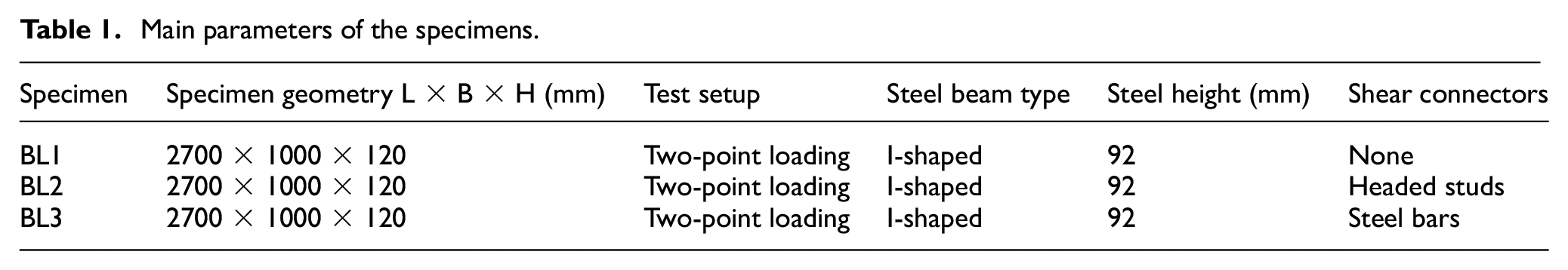
The shear connectors were the variables considered among the specimens. BL1, as the control group, was designed with no shear connectors, as illustrated in Figure 2(a). BL2 had the same dimensions as BL1, except for its additional 25 pairs of horizontal shear studs, which were welded onto the beam web to provide the shear connectors, as shown in Figure 2(b). BL3, which was designed with shear connectors and employed transverse steel bars instead of welded studs, is presented in Figure 2(c). The identical side views of the specimens are shown in Figure 2(d).
Mechanical properties of the materials
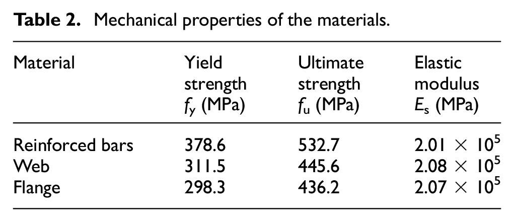
In the test, the strength classes of the concrete and steel were C30 and Q235B according to Chinese code for design of concrete structures (50010-, 2010). The tested compressive strengths of the 150 × 150 × 150 mm3 concrete cubes were 32.3 MPa on average (28 days). For the steel, the tested tensile strengths of the flange and web were approximately 300 MPa at yield and 440 MPa at failure. The measured yield strength and ultimate strength for the 8 mm rebar were 378.6 MPa and 532.7 MPa respectively; the details of the material test results are summarized in Table 2.
Mechanical properties of the materials.
Loading and measuring
All specimens were tested on a microcomputer electrohydraulic servo pressure testing machine that provides a maximum monotonic load of 5000 kN, as shown in Figure 3. Through the distributive girder, the load was applied at two locations along the length of the specimen: at the center of the cross-section and 0.45 m from the midspan. The loading procedures were divided into two parts. The load was gradually increased by 10 kN per stage before the load reached 100 kN in the first part of the test, and in the second part of the test, the increment of the load applied was 5 kN per stage until the specimen failed.

Test setup for the specimens under distributed loading.
To measure the midspan deflection and loading capacity of composite slim floor beams under a negative bending moment, three LVDTs, 1-2, 1-3, and 1-4, were arranged under the steel beams. In addition, the end-slips of the specimens were recorded by LVDTs 1-1 and 1-5. The side view in Figure 4(a) presents the position of the LVDTs and the strain gauges.

Measuring arrangement: (a) positions of the LVDTs and strain gauges (in mm) and (b) detail of the strain gauges.
For each specimen, the strain gauges layouts were identical. Strain gauges SG-2 and SG-5 were placed at the top on each side of the flange of the asymmetric steel beam, while strain gauges SG-2, SG-3, and SG-4 were arranged at the center of the midspan steel cross-section, and strain gauge SG-6 was located on the surface of the concrete. More details regarding the location of the strain gauges are provided in Figure 4(b).
Test results
Failure mode
The failure mode of each specimen was dominated by flexural effects as shown in Figure 5(a), exhibited by crushing of the concrete in the compression zone (Figure 5(b)). The results show the shear connectors could considerably reduce the slippage of the concrete and steel beam of composite slim floor beams, especially when the applied load reached a higher level. This effect was less distinct in the specimen with headed studs (BL2) but more distinct in the specimen with transverse steel bars (BL3). Regarding the loading capacity, although the initial flexural behavior of the specimens was identical, a slight reduction in the loading capacity at the final stage was observed in the specimen without shear connectors.

Typical failure patterns of the specimens: (a) failure mode and (b) top crushing of the concrete.
Load-deflection behavior
The three specimens demonstrated identical behavior during the testing procedures, so BL1 is taken as an example. In the first part of loading, the load-deflection curve developed linearly before 25% of the peak load was reached, and the specimen underwent deformation in an elastic state, without cracking. As Figure 6(a) to (c) shows, vertical cracks began to reach the surface of the concrete accompanied by a quiet sound when the load increased to 45% of the peak load; additionally, the load-deflection curve turned, indicating the yield of the steel shape in the tensile area, and the beginning of the elastic-plastic stage of deformation.

Cracking of the specimens: (a) BL1-no shear connectors, (b) BL2-headed studs, and (c) BL3-transverse steel bars.
In the second part of the test, with the increase in the load to 75% of the peak load, cracks gradually propagated through the entire midspan cross-section, while the steel shape in the tensile area yielded and entered the plastic deformation stage, resulting in the conspicuously decreased slope of the linear segment of the load-deflection curve. During the failure stage, while the concrete in the compression zone was partially crushed, the load-deflection curve maintained a relatively gradual decline until the end of loading, showing good ductility. According to the analysis of the load-deflection curves shown in Figure 7(a), the experimental ultimate flexural strength of the specimens was obtained by the twice elastic slope criterion, as shown in Figure 8.

(a) Load-deflection curves and (b) load-displacement curves.

Determined the ultimate flexural strength of the test specimens.
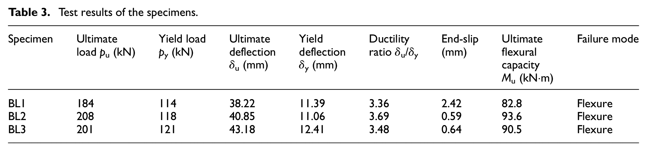
As illustrated in Table 3, the analysis of the ultimate flexural strength demonstrates that the shear connectors notably influenced the flexural capacity of the slim floor beam. The ultimate flexural loads of BL2 and BL3 were 13.0% and 9.2% higher than those of BL1 respectively.
Test results of the specimens.
End-slip
The shear connectors shown in the above figures also influence the end-slip between the concrete and steel beam. Figure 7(b) shows that each specimen exhibited identical behavior in the initial stage of loading, and the load-displacement curves developed linearly and smoothly with the loading increment and showed distinct elastic characteristics. With the continuation of loading, the load-displacement curves of BL2 and BL3 exhibited gradual increases in slope while the load-displacement curve of BL1 exhibited a turn, meaning that the end-slip increased drastically. An analysis of the test results suggests that the average end-slip of the specimen without shear connectors was six times that of the specimen with shear connectors. The end-slips of the two specimens with headed studs and transverse steel bars were in low disparity regarding the ultimate flexural strength of each specimen (0.59 mm and 0.64 mm), while the ultimate flexural strength was very close; thus, in the process of deriving the calculation method, the effect of the slip is neglected. However, the headed studs have higher yield strength values than the steel bars and, therefore are conducive to the ultimate flexural strength of the composite slim floor beam.
Strain distribution in the cross-sections
η is the ratio of the measured flexural capacity to the ultimate flexural capacity obtained from the test. As Figure 9 shows, during the first stage of loading, the distribution of the strain was almost linear along the cross-section, and the strains at the bottom of the steel beam and the top of the concrete were similar. This result shows that slippage did not appear during the procedure and reveals a sufficient composite action. In this stage, the initial neutral axis heights of BL1, BL2, and BL3 were all 64 mm.

Strain distribution curves along the specimen height: (a) BL1-no shear connectors, (b) BL2-headed studs, and (c) BL3-transverse steel bars.
After the initial cracking, the tests entered the second stage of loading. Although all specimens behaved only slightly differently in the previous stage, the slippage between the concrete and steel beam of BL1 was much more substantial and occurred earlier than in the other specimens in the second stage. The strain at the bottom of the steel beam and at the top of the concrete increased at different rates, prompting a rise in the height of the plastic neutral axis. Because of the existence of the shear connectors, the ultimate strains of BL2 and BL3 were approximately 20% larger than that of BL1. In this stage, the final neutral axis heights of BL1, BL2, and BL3 were 78 mm, 80 mm, and 79 mm, respectively.
Throughout the experiment, nearly all tensile force was resisted by the steel shape, while all compressive stress was born by the concrete. The results present the variation in the plastic neutral axis and indicate that the plain section assumption was satisfied in these specimens.
Numerical studies
More specimen dimensions are simulated by the finite element software ANSYS 18.2, a powerful package for nonlinear structural analysis. The distribution of reinforced bars and the cracking and failure of concrete can be simulated accurately by the software.
FE model description and boundary conditions
To comply with the test specimen conditions, the specimens in the finite element simulation were all simply-supported composite slim floor beams, which were subjected to a two-point symmetric loading configuration. Rigid plates were installed at the loading point and bearing as shown in Figure 10 to eliminate the convergence difficulties caused by the stress concentration. The boundary conditions of the beam supports were modeled on the bottom flange of the steel beam. At one support, translations in global directions X, Y, and Z were restrained, while at the other support, translations in global Y and Z directions were restrained.

Finite element model.
Element types and material property
To accurately calculate the composite slim floor beam with three types of shear connection under a positive bending moment in a nonlinear finite element, and correctly reflect its stress process, the following corresponding material relationships and element types were selected.
Steel component: Two solid elements and one bar element were used in the finite element analysis of steel. The steel flange of the steel beam adopted the SOLID45 element and the web plate of the steel beam adopted the PLANE42 element; both elements were eight-node and three-dimensional solid elements. The reinforcing bars embedded in the concrete slab were modeled using the spar element LINK8, a three-dimensional uniaxial tension–compression element with three degrees of freedom at each node that exhibits plasticity, creep, swelling, and stress stiffening. A multi-linear isotropic reinforcement model with the Von-Mises yield criterion was adopted for the steel materials. As shown in Figure 11(a), the secondary plastic flow model was selected as the constitutive relationship. The stress-strain relationship was divided into the two stages of the elastic stage and yielding stage. The yield strengths of different steel elements were the same as the experimental test and are summarized in Table 2.
Concrete component: The concrete elements were modeled by SOLID 65, an eight-node and three-dimensional solid element. It is capable of modeling the crushing of concrete during compression and cracking with tension. For the material, the concrete adopted was the multi-linear isotropic strengthening model. The failure criterion was the five-parameter failure criterion of Willan-Warnke. The stress and strain relationship shown in Figure 11(b) was determined in accordance with the Chinese code for concrete design (50010-, 2010), using equations (1) and (2). Accordingly, the concrete reached its maximum compressive stress at the strain value of 0.002, and beyond the peak stress, the concrete strain reached the maximum value of 0.0033.


To simulate vertical and horizontal slippage and vertical lift between the concrete slab and steel beam, headed studs were simulated by three orthogonal spring units, in COMBIN39. Ollgaard et al. (1971) conducted tests and proposed the load-slip relationship of headed studs by regression analysis of using a mathematical model, and the load-slip curve is derived from equation (3), as presented in Figure 11(c).


(a) Constitutive relationship of steel, (b) constitutive relationship of concrete, and (c) load-slip curve of the headed stud.
Model validation and parameter study
Validation
To verify the finite element model, one specimen was modeled with the same configuration as BL2 (experimental specimen with headed studs), and the finite element results were compared with the test results. As shown in Figure 12(a) to (c), it was observed that the computational curves of the deflection generally agreed with the test results; the difference between the two curves was negligible. The end-slip of the experimental specimen was lower than that of finite element in the same load because the friction and the encase force between the steel beam and the concrete slab also provided part of shear capacity of the experimental specimens, but this could not be reflected on the finite element model; the failure modes and the crack positions were similar. Thus, compared with the two engineering investigation methods, the developed finite element models are reliable and sufficiently accurate, and can be used to predict the bearing strength as well as the failure mechanisms of composite slim floor beams.

Comparison of the experimental and finite element results: (a) load-deflection curves, (b) load-slip curves, and (c) cracks.
Effect of slab thickness to load capacity
The concrete slab thickness varied only in the cast-in-place portion from 60 mm to 100 mm; the precast slab remained unchanged, with 60 mm thickness. The headed studs were taken as the shear connectors given their excellent behavior in the experiments. The other material properties adopted were the same as those for specimen BL2. The results shown in Figure 13(a) compare the ultimate flexural strength of three composite slim floor beams with slab thicknesses of 120 mm (BL2), 140 mm (TL1), and 160 mm (TL2). In comparison with the three specimens, the ultimate flexural strength increase by 11.2% and 33.3%, respectively, when the thickness of the concrete slab increased by 20 cm and 40 cm, respectively. It can be observed that the stiffness of the concrete slab increased with increasing concrete slab thickness. Therefore, increasing the thickness of the concrete slab can contribute to the ultimate flexural strength of the composite slim floor beam.

Variation of parameters: (a) concrete slab thickness, (b) yield strength of steel, and (c) strength classes of concrete.
Effect of steel strength to load capacity
The influence of the steel beam on the behavior of composite slim floor beams was investigated by varying the yield strength values of the steel beams. The steel strength grades of Q235, Q345, and Q390, which represent yield points of steel at 235 MPa, 345 MPa, and 390 MPa, respectively, are widely produced and employed in mainland China. Therefore, the values of 235 MPa (BL2), 345 MPa (SL1), and 390 MPa (SL2) were adopted for the numerical investigations, and the obtained results were compared in the mid-span deflection curves shown in Figure 13(b). In comparison with the three specimens, when the yield strength of steel increased by 110 MPa and 155 MPa, the ultimate flexural strength increased by 28.1% and 36.6%, respectively. It is worth noting that the increase in the yield strength of steel has significant effects on the stiffness and ultimate flexural strength of the composite slim floor beam. This phenomenon can be explained by the fact that the buckling effect that could affect the steel web is not a concern for the composite slim floor beam, since the steel beam is highly encased within the concrete slab. Therefore, the vertical and longitudinal shear capacities of the composite slim floor beam can be increased when the steel beams are encased in the concrete slab, which effectively enhance its ultimate flexural strength.
Effect of concrete strength to load capacity
The results when changing the strength classes of concrete when the material properties adopted are the same as BL2 are as shown in Figure 13(c). In comparison with the three specimens, when strength classes of concrete increased by 5 MPa (CL1) and 10 MPa (CL2), the ultimate flexural strength increases by 4.8% and 11.9%, respectively. The results show that the strength of concrete hardly affects the ultimate strength of the composite slim floor beam because the area of the compressive region of the concrete never exceeds the limit, and the failure mode of the specimen is not brittle failure. However, the concrete provides an encasement for the steel beam and, therefore, sufficient composite behavior within the beam section; this is the reason why the ultimate strength values of the test pieces have slightly improved. Therefore, it is suggested that the concrete should be employed in relatively cost efficient strength classes, which not only is conducive to the flexural behavior of the composite slim floor beam but also improves its fire resistance performance.
Analysis and discussion
The composite slim floor beam with a steel beam at 390 MPa yield strength exhibited higher stiffness and flexural capacity than those of 345 MPa and 235 MPa. An identical conclusion can be derived on the variation of slab thickness: the slab with 160 mm thickness exhibited higher stiffness and flexural capacity than those of 120 mm and 140 mm. However, in the comparison of C30, C35, and C40 concrete, the effect of increasing the strength classes of concrete was limited.
Ultimate flexural capacity calculation method
The position of the neutral axis plays a decisive role in the subsequent analysis. To provide simple design equations for calculating the flexural capacity of the composite slim floor beam, the neutral axis in the beam is simplified into three positions.
The plastic neutral axis is in the concrete at the top of the steel beam.
The plastic neutral axis is in the upper flange of the steel beam.
The plastic neutral axis is in the steel beam web.
Basic assumption
The analytic results of the strain distribution show that the steel beam and concrete work together under the load and that the composite effect is sufficient. Hence, based on the above findings, the following assumptions can be employed in deriving the formulas.
The plane section assumption is applied to the composite section.
Both the steel beam and the reinforced bars are elastic-perfectly plastic.
The compression of the concrete is considered while the compression of the steel bars is ignored.
The concrete under tension is neglected.
The longitudinal shear force is provided by the bond force between the concrete and the steel beam, and the slippage between them is neglected.
Determination of the ultimate flexural capacity
The plastic neutral axis is located at the top of the steel beam
For the position of the neutral axis and the distribution of stress and resistance shown in Figure 14(a), if the criterion


(a) The plastic neutral axis located at the top of the steel beam, (b) the plastic neutral axis located at the upper edge of the steel beam, and (c) the plastic neutral axis located at the steel beam web.
The plastic neutral axis is located at the upper edge of the steel beam
In Figure 14(b), due to the variation in the neutral axis, the stress and resistance were redistributed. In this situation, the compressive resistance effect of the upper flange of the steel beam was considered to simplify the calculation of the centroid of the steel beam. When

The plastic neutral axis is located at the steel beam web
In this condition, it was assumed that the neutral axis passes through the web of the steel beam as illustrated in Figure 14(c). The compressive resistance effect of the steel beam was considered and simplified. If the premise of

Results comparison
By applying the proposed methodology, the theoretical values of the ultimate flexural strength of resistance, as well as the design values, were calculated for the specimens tested in this study and are presented in Table 4. The results show excellent agreement among the experimental, theoretical and finite element values of the ultimate flexural strength. A refined model should be developed when more experimental data becomes available.
Comparison of the experimental, theoretical, and finite element results.
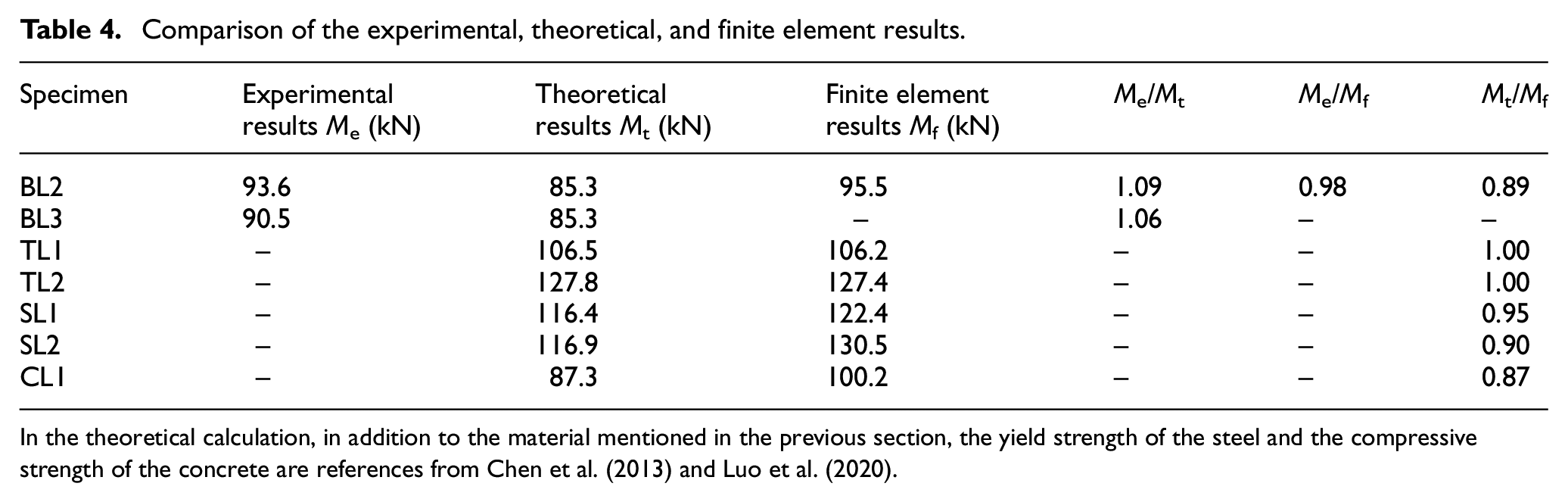
In the theoretical calculation, in addition to the material mentioned in the previous section, the yield strength of the steel and the compressive strength of the concrete are references from Chen et al. (2013) and Luo et al. (2020).
Conclusion
To understand the ultimate flexural strength of composite slim floor beams and determine a simplified calculation method, three slim floor beam specimens were tested and studied in this article. Combine with the experimental results, the finite element method and the theoretical calculation, the flexural strength and end-slip of slim floor beams were analyzed, and used to derive formulas for the ultimate flexural strength at three positions. The main conclusions drawn from this work are as follows:
The composite slim floor beam exhibits excellent bending resistance, and the steel and concrete are well combined. The section strain of a slim floor beam conforms to the plane section assumption. When deriving the ultimate flexural strength formulas, the steel and concrete could be considered to work together.
The shear connectors of the specimens efficiently reduced the slippage between the concrete and steel shape and enhanced the stiffness and flexural capacity of the composite slim floor beam. The utilization of headed studs welded onto the steel beam improved the performance of the slim floor beams, while the utilization of transverse steel bars with pass-through holes are advantageous due to their convenient construction.
The reasonable constitutive relationships of the reinforcement and concrete were selected, and a verified FE model for the composite slim floor beam was developed to conduct parametric studies, which broadened the available experimental results about the mechanical performances. The results indicate that a higher strength steel beam and a thicker concrete slab can effectively enhance the stiffness and flexural capacity of the composite slim floor beam, while the effect of increasing the strength classes of concrete is limited.
Based on plastic mechanics and limit analysis theory, a simplified calculation method was derived to estimate the ultimate flexural strength of a composite slim floor beam with shear connection (ignoring slip).
Footnotes
Acknowledgements
The funding, cooperation and assistance of many people from the organization are greatly acknowledged.
Declaration of conflicting interests
The author(s) declared no potential conflicts of interest with respect to the research, authorship, and/or publication of this article.
Funding
The author(s) disclosed receipt of the following financial support for the research, authorship, and/or publication of this article: This research was funded by the National Science Foundation of the People’s Republic of China (No. 51308269,51668027, 51708486, 52068068).