
Abstract
Application of basalt fibre reinforced polymer (BFRP) bar reinforced seawater sea-sand concrete structures in marine and coastal buildings could bring both environmental and economic benefits. As BFRP bar reinforced seawater sea-sand concrete members are likely to be exposed to temperature variations during their service life, the bond durability between BFRP bar and seawater sea-sand concrete should be well understood. This paper investigated the effects of thermal cycling, such as target temperature (i.e. amplitude of variation) and cycling times, bar diameter and concrete strength on the bonding behavior of BFRP bars in seawater sea-sand concrete by pullout test. It is found that target temperature and cycling times lead to a significant reduction of BFRP bar-to-seawater sea-sand concrete bonding, which is mainly attributed by the degradation of BFRP under thermal cycles. Through the method of scanning electron microscopy, microstructure of BFRP is examined and the bond mechanism considering the effect of temperature variations is clarified. Finally, theoretical model is proposed to predict the bond stress-slip relationship of BFRP bars in seawater sea-sand concrete. Accuracy of the predictions is validated by the experimental results.
Introduction
As the most popular construction material, concrete is world-widely used and consumes a large amount of fresh water and river sand. In recent years, river sand resource has been in shortage, leading to an increase in its price. Moreover, excessive exploitation of river sand leads to ecological problems. In some remote and marine areas, the freshwater resource is also very scarce. One of the solutions is to develop marine resources, including the usage of seawater instead of fresh water and sea-sand instead of river sand. Sea-sand generally has the features of desirable particle size, high hardness and less mud content, which is suitable as constructional sand (Xiao et al., 2017). Nevertheless, chloride ion in seawater and sea-sand introduces severe corrosion problem to carbon steel reinforcements. At present, sea-sand after desalination treatment has been used as constructional sand in buildings to solve the river sand scarcity in coastal areas and to achieve economic and social benefits (Limeira et al., 2010; Liu et al., 2016; Xiao et al., 2017). Seawater sea-sand concrete (SSC) which uses untreated seawater and sea-sand has a wide application prospect (Guo et al., 2020; Li and Zhao, 2020). It can reduce material and transportation costs, avoid desalination treatment and shorten construction period, especially for island and port buildings. However, the corrosion problem caused by SSC should be properly solved, such as by using corrosion-resistant reinforcements.
Due to the advantages of high strength, light weight, good corrosion resistance, fibre-reinforced polymer (FRP) materials have been gradually applied in concrete structures, such as FRP plates (Pan et al., 2019; Zhou et al., 2015), FRP bars (Wang et al., 2017b; Zheng et al., 2018) and FRP tubes (Fang et al., 2019; Li et al., 2016, 2018b; Xiong et al., 2018, 2020; Zeng et al., 2020). Due to its high corrosion resistance, FRP has the potential to be used in SSC. FRP bar reinforced members have been successfully applied in bridges (Benmokrane et al., 2006; El-Salakawy et al., 2005; Zheng et al., 2018) and buildings (ACI440.1R-15, 2015). Recently, some studies have been conducted on FRP bar reinforced SSC members, such as beams (Dong et al., 2018b; Li et al., 2018a), slabs (Gao et al., 2020), columns (Xiong et al., 2022) and walls (Zhang et al., 2019). These studies demonstrated the applicability of FRP bar reinforced SSC structures.
The mechanical behavior of FRP bar reinforced concrete members is mainly controlled by the mechanical behavior of FRP bars and concrete and the bond performance between them. The ribs of FRP bars are weaker than those of steel bars. It can be observed that the ribs of FRP bars were always damaged after pull-out tests (Wei et al., 2019). Since the bond performance between FRP bars and concrete usually influence the cooperative working ability of FRP bars and concrete, researchers have paid much attention to their bond performance. The mechanical behavior of concrete has a great effect on the bond performance between FRP bars and concrete. Generally, the bond strength increases with the increase in concrete strength. Achillides and Pilakoutas (2004) observed that concrete strength could affect the bond failure modes. Bond failure occurred at the surface of FRP bar for low strength concrete, whereas the failure interface changed to concrete matrix for high strength concrete. Islam et al. (2015) found that when the thickness of concrete cover was smaller than 2.5 times of the bar diameter, the bond strength could be improved by increasing the thickness of concrete cover to enhance the confinement effect. The mechanical behavior of FRP bars also plays a key role in the bond performance between FRP bars and concrete. The surface texture of FRP bars also can influence the bond performance greatly (Baena et al., 2009). Because ribs can enhance the mechanical interlocking, deformed FRP bars have a good bond behavior. However, compared with the studies on the bond performance between FRP bars and plain concrete, the studies on the bond performance between FRP bars and SSC are relatively less (Liao et al., 2022). Wei et al. (2020) investigated the high strain rate effect on the bond performance between FRP bars and sea-sand concrete, and observed that the high strain rate obviously changed the bond mechanism. Dong et al. (2016a; 2018a) found that the temperature, aging, seawater environment, and bar types have important effects on the bond behavior between FRP bars and SSC, and developed a method to estimate the bond strength. Hence, to promote the application of FRP bar reinforced SSC structures, further studies on the bond performance between FRP bars and SSC are required. Comparing to glass or carbon FRP, basalt FRP has the advantages of low price and less harm to environment during manufacturing. Several studied have been conducted on the pullout behavior of BFRP bars in concrete. El Refai et al. (2015) indicated that due to the different elastic moduli, the bond strength between concrete and BFRP bars was smaller than that between concrete and GFRP bars. Xiong et al. (2021a) investigated the bond behavior between BFRP bars and recycled aggregate concrete and proposed bond-slip models. In general, failure mode of BFRP bar debonding is similar to that of GFRP and CFRP bars.
In addition to static loads, concrete structures are usually subjected to various environmental actions (Dong et al., 2016b; He et al., 2021; Sun et al., 2020; Xiao et al., 2022). Daily temperature is one of the most common types of environmental loads. In some coastal areas, the surface temperature of concrete could reach 60–70°C if being directly exposed to sunlight, and the temperature could quickly decrease during the night or by rainfall, resulting in a periodic change of temperature. The internal stress of concrete caused by daily temperature variation can lead to cracks, reducing the durability of concrete structures (Tang et al., 2021). An et al. (2020) analyzed the influence of temperature cycling on the mechanical behavior of high-performance concrete, and indicated that the compressive strength, splitting strength, and elastic modulus decreased with the increase in temperature cycling times. Liu et al. (2018) found that the static and dynamic behavior of recycled aggregate concrete decreased obviously due to the daily temperature variations. For FRP bar durability, Wang et al. (2017a; 2018b) found that as the temperature increased, the interlaminar shear strength and tensile strength of FRP bars decreased greatly. Lu et al. (2020) and Xie et al. (2022) discussed the durability of BFRP bars at different temperatures, and indicated that the tensile strength of BFRP bars decreased when the temperature increased. For the bond durability, Solyom et al. (2020) studied the bond behavior between GFRP bars and concrete under the temperature levels ranging from 20 to 300°C, and observed that the bond strength decreased from 13.3 MPa to 1.1 MPa. Wang et al. (2018a) indicated that the increased temperature would deteriorate the GFRP bar-coral concrete interface, resulting in a decrease in bond strength. Most of the past research is limited to a constant temperature. However, a structure is likely to subjected to temperature variations during its service life. Currently, no studies have been conducted on the effect of temperature variations on the bond durability of BFRP bars in concrete.
In this paper, bond behavior between SSC and BFRP bars subjected to daily temperature variations were investigated to fill the above-mentioned knowledge gap. By pullout tests, effects of the bar diameters, concrete strengths, temperature cycling times, and target temperatures on the failure modes, bond stress-slip curves and bond strength were studied. With the help of scanning electron microscopy (SEM), degradation mechanisms of bond between SSC and BFRP bars were analyzed. Finally, theoretical models were proposed to predict the bond stress-slip relationship of BFRP bars imbedded in SSC after thermal cycles. This study would provide guidance to the durability design of BFRP bar reinforced SSC structures subjected to temperature variations.
Experimental program
Materials
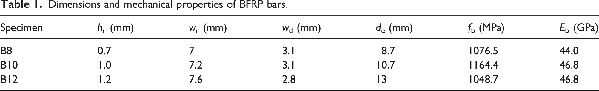
Deformed BFRP bars with three different diameters (i.e. 8, 10 and 12 mm) were selected in this study. Definitions for bar rib dimensions are illustrated in Figure 1, in which hr is the height of ribs, wr is the width of ribs and wd is the width of dents. Dimensions and mechanical properties of FRP bars are summarized in Table 1, in which the bar label consists of letter “B” followed by the nominal diameter. For each BFRP bar group, five 200 mm long BFRP bars were used for the measurement of equivalent diameter (de) by a drainage method (Wei et al., 2019). Based on the manufacturing data provided by supplier, glass transition temperature of BFRP bars in this study is about 120°C. Uniaxial tensile test was conducted according to ACI440.3R-12 (2012) for 800 mm long BFRP bars to measure the mechanical properties, including tensile strength (fb) and Young’s modulus (Eb). Ends of BFRP bars were inserted to steel tubes filled with Sikadur 330CN binder to avoid end failure. During a tensile test, steel tubes were griped by the test machine and the BFRP bar was fractured in the middle. Five bars were tested for each bar diameter and the average values for fb and Eb are reported in Table 1. BFRP bars. Dimensions and mechanical properties of BFRP bars.
Seawater sea-sand concrete (SSC) was mainly composed of ordinary Portland cement (with a strength grade of 42.5 MPa and an apparent density of 3112 kg/m3), sea-sand, coarse aggregate (granite gravel with continuous gradation of 5–20 mm), seawater and superplasticizer (SP). Chemical compositions of cement are 19.6% SiO2, 68% CaO, 5% Al2O3, 3.5% Fe2O3 (in weight). Fineness modulus of sea-sand is 2.6 and its apparent density is 2893 kg/m3. Simulated seawater was used in this study that contained NaCl (24.53 g/L), MgCl2(5.2 g/L), Na2SO4 (4.09 g/L), CaCl2 (1.16 g/L), KCl (0.695 g/L), NaHCO3 (0.201 g/L), KBr (0.101 g/L), H3BO3 (0.027 g/L), SrCl2 (0.025 g/L), NaF (0.003 g/L), and distilled water [40]. Density of simulated seawater was 1016 kg/m3. The solid mass content and density of SP were 20% and 1030 kg/m3, respectively. In this study, three grades of SSC (i.e. C40, C70, and C90) were prepared (JGJ55-2011, 2011) and the water-to-cement ratio is 0.55, 0.38 and 0.295, respectively. Three identical concrete cylinders were prepared for each grade and compressive test was conducted in accordance with ASTMC39/C39M (2017). The measured average cylindrical compressive strength of SSC was 34.1 MPa, 58.4 MPa and 77.2 MPa for C40, C70 and C90 SSC, respectively.
Simulation of daily temperature
Temperature cycle was used to simulate the daily temperature variation (Figure 2(a)). In a temperature cycle, specimens were heated in an environmental chamber (Figure 2 (b)) to the target temperature (e.g. 40, 60, 80 or 100°C) from the ambient temperature (i.e. 25°C) with a heating rate of 1.25 °C/min and then the target temperature was maintained for 3 h. Thereafter, specimens were naturally cooled down to the ambient temperature in the chamber and the ambient temperature was maintained for another 3 h before starting a new cycle. Two parameters, including the target temperature and temperature cycling times, were selected in this study. Four kinds of temperature variations (i.e. 25–40, 25–60, 25–80, and 25–100°C) were chose to cover the possible daily temperature variations during a summer. Meanwhile, five temperature cycling times (i.e. 30, 60, 90, 120, and 150 times) were selected to consider the influence of a long-term exposure on the concrete behavior and bond behavior. Relative humidity for specimens was set as 70% to simulate the humidity a specimen encountered in a real environment. Simulation of daily temperature variation: (a) cyclic temperature regime; (b) programmable environmental chamber.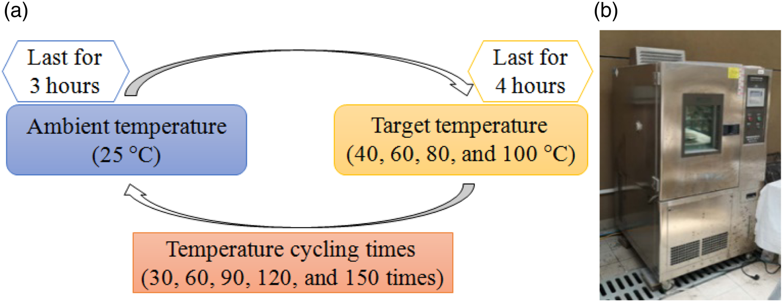
Specimens
A pullout specimen was consisted of an SSC cube and a 500 mm long BFRP bar, as shown in Figure 3. Based on ACI 440.3R-12 (2012) and GB/T 30022-2013 (2012), dimensions of the SSC cube were 150×150×150 mm for BFRP bars with diameter of 8 and 10 mm and 200×200×200 mm for 12 mm diameter BFRP bars. A pullout specimen had four parts, including a free part, a bond part, a deformed part, and a loading part. Length of BFRP bar in the free part was 30 mm. Based on ACI 440.3R-12 (2012), the bond length (la) was equal to 5de to meet the requirement of achieving an effective bonding. In the deformed part, the BFRP bar was not in contact with the SSC cube. BFRP bar in the loading part was strengthened by a steel tube filled with Sikadur 330CN binder and the steel tube was gripped by the test machine during the pullout test. Before the cyclic temperature process, pull-out specimens were standardly cured at temperature of 20 ± 2°C and relative humidity of >95% for 28 days. Pull-out specimen.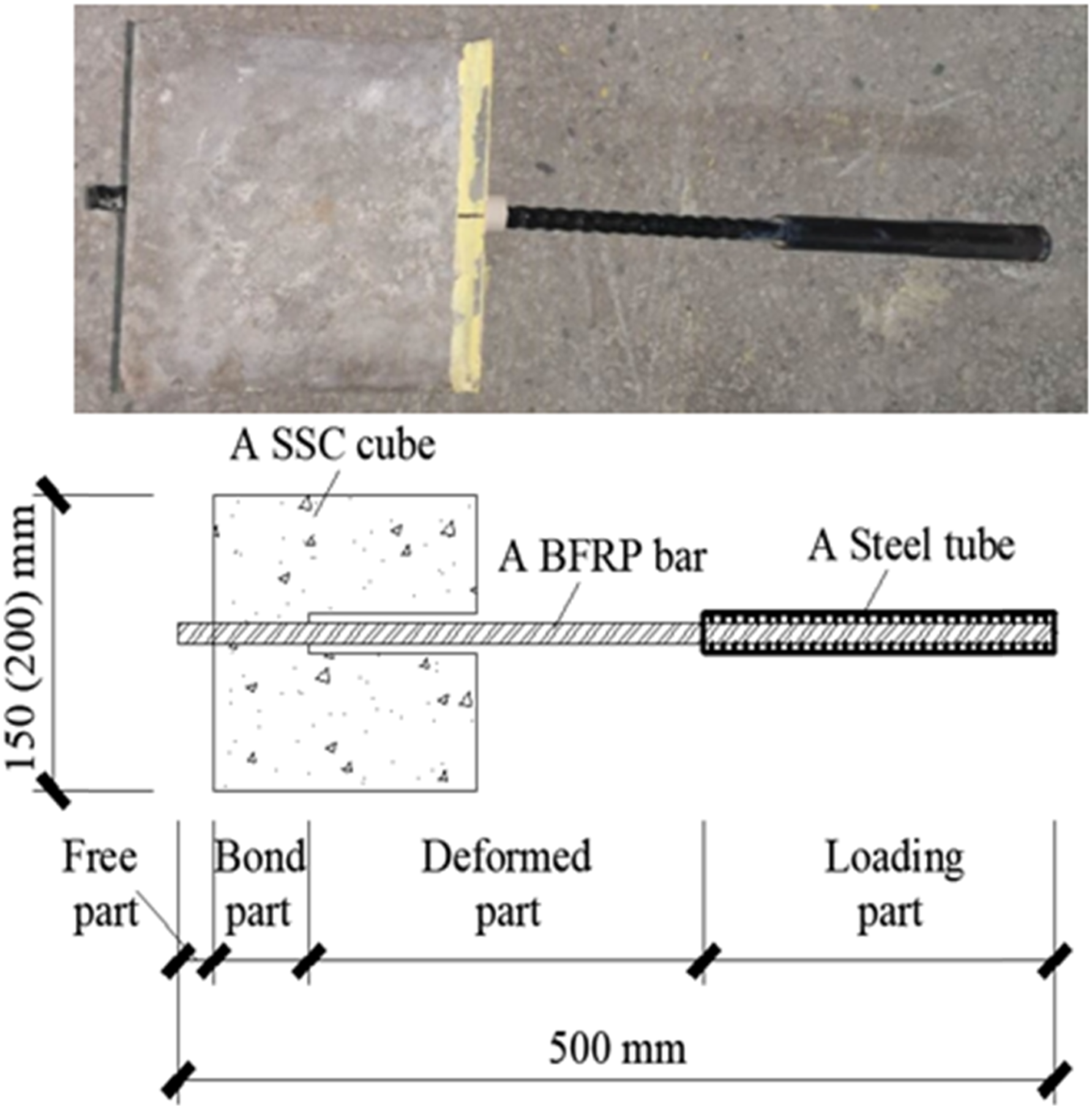
Specimen table.
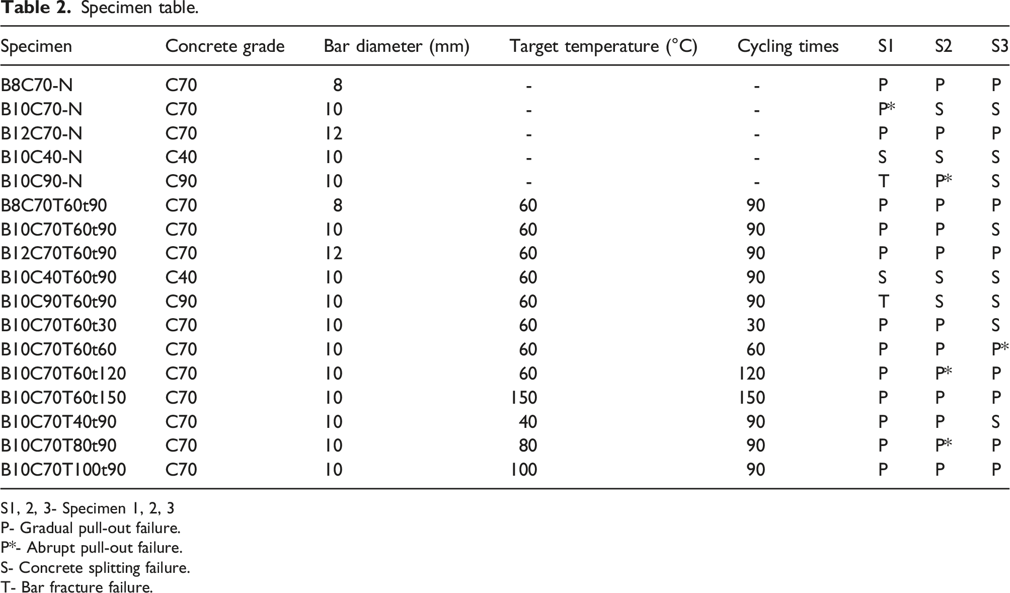
S1, 2, 3- Specimen 1, 2, 3
P- Gradual pull-out failure.
P*- Abrupt pull-out failure.
S- Concrete splitting failure.
T- Bar fracture failure.
Experimental setup and instrumentation
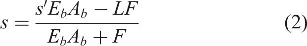
A test device was designed for pullout tests, as plotted in Figure 4. A ball joint was designed to make sure a pure tensile force was applied during the loading process. Moreover, gypsum was used for the contact surface between concrete cubes and steel plates so that the additional friction generated at the contact surface can be effectively reduced. An MTS370 fatigue testing machine was employed and the loading rate was 1.2 mm/min with displacement control. It was assumed that the bond stress was uniformly distributed along the imbedded bar. Bond stress (τ) was equal to the pullout force (F) divided by the bond area, as expressed in equation (1). Slip (s) was modified by considering the deformation of the BFRP bar at the deformed part and it is defined in equation (2). Experimental setup: (a) sketches of pullout test; (b) photo of pullout test.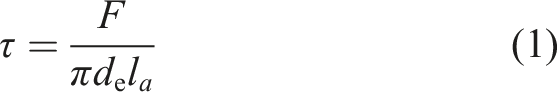
Experimental results
Failure modes
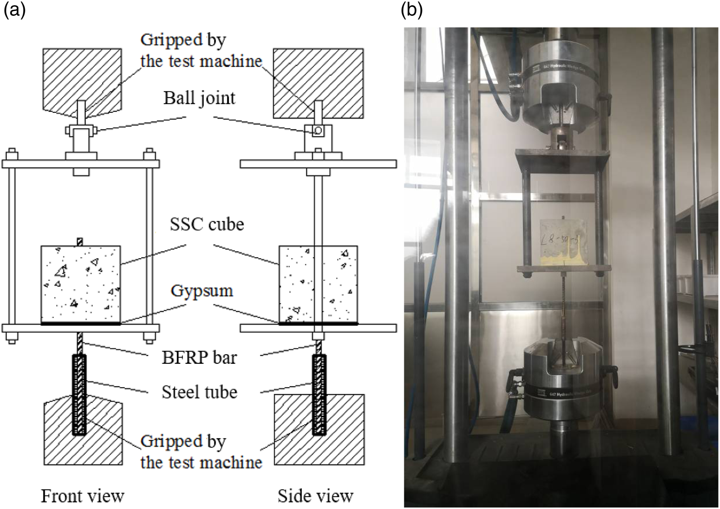
Failure modes of specimens tested in this study include concrete splitting, bar fracture and bar pullout (Figure 5 and Table 2). When a BFRP bar was pulled out from an SSC cube, hoop stress was developed in concrete owing to the wedging action of bar ribs. If the hoop stress exceeded the tensile strength of concrete, abrupt splitting failure, which was a brittle failure, occurred in concrete (Figure 5 (a)). In this study, specimen B10C40-N, B10C70-N, B10C40T60t90 and B10C90T60t90 were failed by concrete splitting, which was probably due to the relative smaller size of SSC cubes and low tensile strength of concrete in the first three specimens, and the significant shrinkage of high strength concrete (i.e. low water-to-binder ratio) under thermal cycles (Chu et al., 2012) for specimen B10C90T60t90. In standards such as ACI 440.3R-12 (2012) and GB/T 30022-2013 (2012), the size of concrete cube is fixed or only depends on the bar diameter, which leads to a concrete splitting failure in some specimens tested in this study. It seems needed to provide a more specific requirement for the dimensions of concrete cube by considering the possible influence of concrete strength, bar diameter and bar surface texture to avoid the splitting failure. Few specimens (i.e. B10C90-N-S1, B10C90T60t90-S1) were failed by a fracture of BFRP bar, which was probably caused by the low product quality of these bars. For these specimens, the tensile strength of BFRP bar was lower than the bond resistance. As fracture failure of BFRP bar was abrupt and resulted in a completed loss of load-carrying capacity, it belonged to a brittle failure. Failure modes: (a) Concrete splitting failure; (b) facture failure of BFRP bar; (c) Abrupt pull-out failure; (d) Gradual pull-out failure.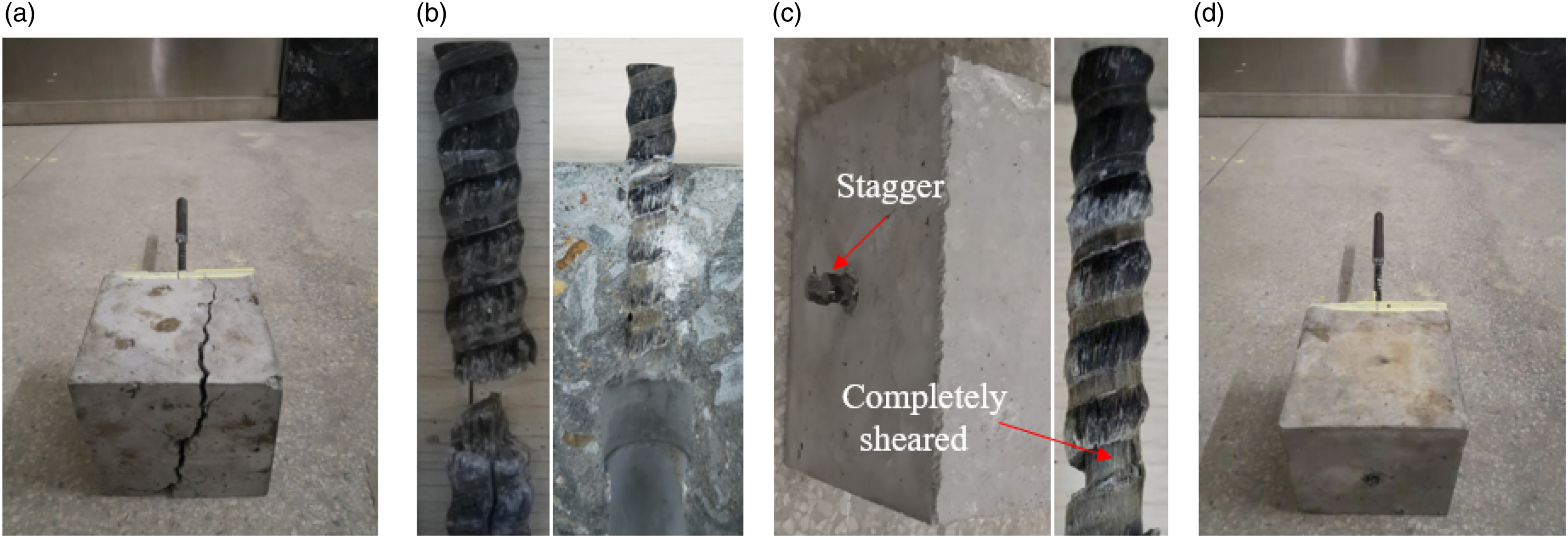
Based on its characteristics, pullout failure of BFRP bar could be further divided as abrupt pullout and gradual pullout failure. As shown in Figure 5 (c), when the BFRP bar was abruptly pulled out from SSC cube, shear failure occurred between the core area of bar and the outer layer, and obvious delamination was observed. During the manufacturing of BFRP bars, voids may exist between fibers and resin, which was prone to stress concentration when a bar was pulled out from an SSC cube. If the shear stress exceeded the interlaminar shear strength, shear failure occurred. With the development of shear failure process, effective shear area of BFRP bar kept decreasing until a completed separation between bar core area and its outer layer, resulting in an abrupt pullout of bar. This failure mode also belonged to a brittle failure. In this study, an abrupt pullout failure only occurred in few specimens. In specimen group such as B10C70T60t60, B10C70T60t120 and B10C70T80t90, one specimen was failed by the abrupt pullout failure whilst the other two repeated specimens were failed by the gradual pullout failure. The abrupt pullout failure was likely caused by the low interlaminar shear strength of BFRP bars with poor quality control. Nevertheless, most of the specimens were failed by a gradual pullout of BFRP bars due to the debonding between bar and concrete (Figure 5 (d)). Bar ribs were successively damaged at the bar-to-concrete interface. This failure mode was ductile and the bond strength between BFRP bar and SSC concrete was fully utilized.
Since the failure modes of concrete splitting, FRP bar fracture and abrupt pullout are brittle and the bond strength cannot be fully utilized, these failure modes are tried to avoid by detailing designs. Discussions in this paper only focuses on the behavior of specimens failed by the gradual pullout of BFRP bars. It is necessary to mention that in specimen groups of B10C40-N, B10C70-N and B10C90-N, which are intended to investigate the effect of concrete strength on pullout behaviour, group B10C40-N and B10C70-N were failed by concrete splitting and group B10C90-N was failed by abrupt pullout of bars. The effect of concrete strength on pullout behaviour cannot be directly analyzed in this study.
Interface damage in pullout specimens
Damages of interface of pullout specimens were observed by breaking the concrete cube into two pieces to expose the inner surface and the photos are shown in Figure 6. For specimen B8C70-N (Figure 6 (a)), fiber layers and concrete debris were observed in SSC cube. Ribs of BFRP bar were completely cut off by shear action and obvious scratches were found on the bar surface. Interface damage of specimen B12C70-N is similar as that of B8C70-N, except that clear ribs could be found in SSC cube as fiber layers were not attached on the SSC surface (Figure 6 (b)). After thermal cycles (e.g. target temperature=60°C, cycling number=90), the concrete surface of specimen B8C70T60t90 (Figure 6 (c)) and B12C70T60t90 (Figure 6 (d)) became slightly yellow and the yellow fibre floccules were observed on bar surface. The interface damages of specimens after thermal cycles were similar as these of unconditioned specimens, which exhibited a cut-off of bar ribs. Furthermore, the diameters of FRP bars did not affect the failure modes of the thermal treated and unconditioned specimens. Interface damage of gradual pullout specimens.
By comparing specimens with the same cycling times but different target temperatures (Figure 6(e) to (h)), it is found that the target temperature did not obviously affect the interface damage mode: bar ribs were completely cutoff and concrete debris and bar ribs were found on the SSC surface. However, the target temperature affected the color of BFRP bars, which changed from gray to light yellow and deep brown with the increase in temperature. This is probably caused by the chemical reaction of resin exposed to temperatures. As shown in Figure 6(i) to (l), the interface damages of specimens with different thermal cycling numbers (target temperature=60°C) are similar, which is also a completely cutoff of bar ribs. Fibre floccules were found on BFRP surface and the cutoff ribs were fixed on the concrete surface. Nevertheless, with the increase in thermal cycling number, the fibre layers became looser due to the increased degradation of resin.
In general, unconditioned specimens and specimens subjected to thermal cycles showed a similar damage pattern at the bar-to-concrete interface. BFRP bar ribs were completely cut off during the pulling process and these ribs were left in concrete. With the increase in target temperature and thermal cycle number, fibre floccules became more obvious on bar surface and the color of the interface also changed, which is related to the degradation of resin in BFRP bar caused by the thermal cycling.
Bond stress-slip relationships
Typical bond stress-slip relationship of pullout specimens is illustrated in Figure 7 (a). At the initial loading stage (oa), bond stress increases linearly with the increase in slip until bond stress reaches about 70% of the bond strength. Thereafter, the curve climbs nonlinearly with the decrease of slope until reaching the first peak point (point b). In these ascending regions (oa and ab), the bond stress is mainly contributed by the mechanical interlocking and friction between BFRP bar and SSC. Due to the deterioration of the interlocking effect, bond stress starts to decrease from point b. As the free end of BFRP bar was pulled into the SSC cube, the interlocking effect and friction force recover to some extent and the bond stress starts to increase again after reaching a valley point (c). Depending on the dimensions, material properties and experiment setup, the second peak point could be either lower (i.e. point d, type I) or higher (i.e. point d’, type II) than the first peak point (b). With a further deterioration of bonding interface and reduction of interface area, the bond stress decreases until a complete pullout of BFRP bars. In this study, bond stress-slip relationship of most specimens belonged to type I, except specimen group B10C70T80t90, B10C70T100t90, B10C70T60t120 and B10C70T60t150, whose curves were categorized as type II. Bond stress-slip curves of pullout specimens: (a) Typical bond stress-slip relationship (b) effect of BFRP bar diameter; (c) effect of target temperature; (d) effect of cycling number.
Bond stress-slip curves of pullout specimens are plotted in Figure 7(b) to (d), in which the bond stress and slip are defined in equations (1) and (2), respectively. For each group, one representative curve was selected to plot. As shown in Figure 7 (b), the shapes of bond stress-slip curves of unconditioned and conditioned specimens are similar with regardless of bar diameters. For unconditioned specimens, the bond stress is enhanced by increasing the bar diameter from 8 mm to 12 mm. For specimens subjected to thermal cycles, the bond stress is increased by changing bar diameter from 8 mm to 10 mm. However, a slight decrease in bond stress is observed when increasing bar diameter from 10 mm to 12 mm (B10C70T60t90 vs. B12C70T60t90). It is found that the recovery of bond stress (i.e. ratio of the second peak stress to the first peak stress) is more significant for conditioned specimens than that for unconditioned specimens.
Bond stress-slip curves of specimens subjected to 90 times of thermal cycles and various target temperatures are plotted in Figure 7 (c). In general, with the increase in target temperature, the first peak bond stress decreases and the ratio of the second peak stress-to-the first peak stress increases. If the target temperature is 80°C or above, the curve type changes from type I to type II. Figure 7 (d) shows the effect of thermal cycling times on the bond stress-slip curves. As expected, thermal cycling is detrimental to the first peak bond stress, which decreases with the increase in thermal cycling times. Specimens subjected to more thermal cycles exhibit a more bond stress recover after the first peak point. The second peak bond stress of specimens with 120 times or more of thermal cycles is higher than other specimens with less thermal cycles. In general, thermal cycling (temperature and cycling times) is detrimental to the bond strength but it seems beneficial to the recovery of bond stress after the first peak point.
Discussions
Effect of bar diameters
In this study, five parameters (i.e. bond strength, residual strength, bond stiffness, slip at bond strength and slip at residual strength) are adopted to represent the bond behaviour between BFRP bar and SSC. Since the recovery of bond stress is mainly caused by the contribution of ribs in BFRP bar’s free end and cannot be utilized in FRP bar reinforced concrete members, bond strength (τb) and slip at bond strength (sb) are defined as the stress and slip corresponding to the first peak point in bond stress-displacement curves (Figure 8). Bond stiffness, which greatly control the deflection of BFRP bar reinforced SSC members, is defined as the secant slope at the point in bond stress-slip curve corresponding to 0.5τb (Xiong et al., 2021a). Residual strength (τc) and slip at residual strength (sc) are defined as the stress and slip at the first valley point in the bond stress-strain curve (i.e. point c in Figure 8). Table 3 summarizes the parameters (i.e. τb, τc, Kb, sb, and sc) of specimens with gradual pullout failure mode. In Table 3, the representative value (RV) for each group is defined as: (1) if data of two specimens is valid, RV is the average value of them; (2) if data of three specimens is valid and the maximum or minimum value is less than 15% larger/less than the median value, RV is the average value of them, otherwise the median is taken as RV. Effects of bar diameters on: (a) bond strength; (d) residual strength; (c) bond stiffness; (b) slip at bond strength; (e) slip at residual strength. Test results of pull-out specimens.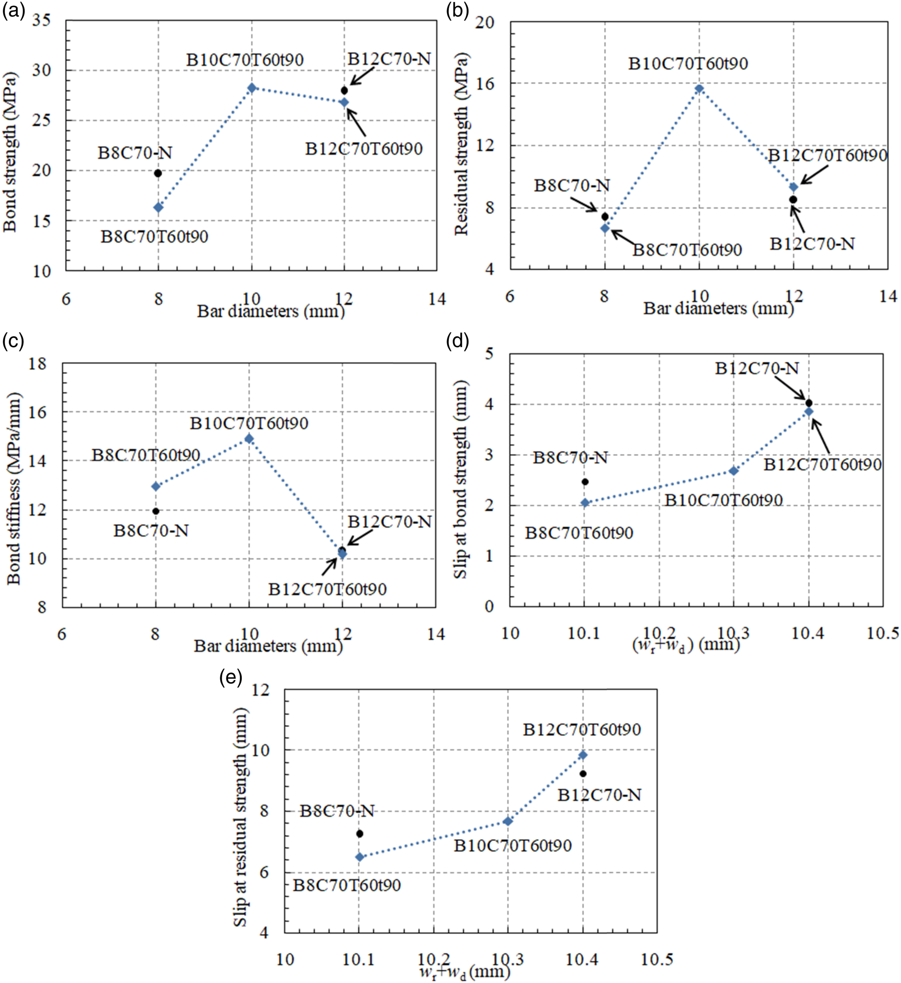
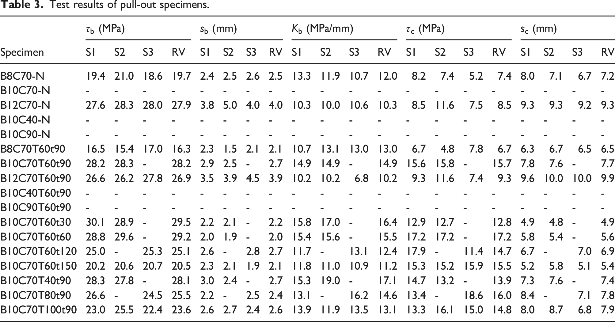
Figure 8 shows the effect of bar diameter on the bond behavior between BFRP bar and SSC. As shown in Figure 8 (a), increasing the bar diameter from 8 mm to 12 mm can enhance the bond strength of unconditioned specimens. Currently, no consensus has been made about the effect of bar diameter on bond strength. Some researchers held the view that bond strength is reduced by increasing rebar diameter, as less bond length is developed and air voids are easy to form for rebars with large diameter (El Refai et al., 2015). However, some experimental results showed bond strength was enhanced by increasing rebar diameter (e.g. (Xiong et al., 2021b)). Hao et al. (2009) found that the mechanical interlocking effect can be greatly improved by increasing the height of ribs in GFRP bars, leading to an increase in bond strength. In this study, rib height of BFRP bar with 12 mm diameter is larger than that of BFRP bar with 8 mm diameter, which would be the main reason to the observed increase in bond strength. Specimen subjected to thermal cycles exhibit a low bond strength than its corresponding unconditioned specimens, which is mainly due to the degradation of BFRP bar under heating. As shown in Figure 8 (a), for conditioned specimens, bond strength is increased by increasing the bar diameter from 8 mm to 10 mm, but a slight drop of bond strength is observed if the bar diameter changes from 10 mm to 12 mm. This is probably caused by the combined effect of bar diameter and rib height. With respect to residual strength (Figure 8 (b)), its changing trend along bar diameter is similar as that of bond strength since the mechanisms are similar for them. Figure 8 (c) shows that the bond stiffness increases first and then decreases with the increase in bar diameter. Past study (Xiong et al., 2021b) indicated that the slip at bond strength and residual strength was related to the summation of rib width (wr) and dent width (wd) of bars. Figure 8(d) and (e) plot the slip vs. wr+wd relationships of pullout specimens. With the increase in wr+wd, a clear increasing trend is observed for slip at bond strength and slip at residual strength.
Effect of target temperature
Figure 9 shows the effect of target temperature on the bond behavior of specimens subjected 90 times of thermal cycles. With the increase in target temperature, the bond strength generally decreases gradually (Figure 9 (a)). The degradation of bond strength is mainly caused by: (1) deterioration of BFRP bar under thermal cycles; (2) deterioration of BFRP bar in alkaline environment of SSC; and (3) degradation of bar-to-SSC interface caused the cyclic expansion and contraction of BFRP and concrete. The plain concrete compressive strength of SSC after thermal cycles is 59.9, 65.7, 58.3 and 50.0 MPa for the target temperature of 40, 60, 80 and 100°C, respectively. It is known that bond stress can be improved by increasing the concrete strength (Yan et al., 2016). The slight increase of bond strength for specimens changing target temperature from 40°C to 60°C is probably caused by the fact that the beneficial effect by increasing concrete strength overrides the detrimental effect of BFRP bar and interface deterioration. As shown in Figure 9 (b), the residual strength first increases then decreases with the increase in target temperature. As the residual strength is related to the free end of BFRP bar, expansion of BFRP bar free end may lead to an increase in residual strength. However, if the temperature is too high (i.e. 100°C), residual strength tends to decrease due to the severe degradation of BFRP bar. With the increase in target temperature, bond stiffness decreases gradually (Figure 9 (c)) and the degradation mechanism is similar as that of bond strength. As shown in Figure 9 (d), the effect of target temperature on the slip at bond strength is insignificant. With the increase in target temperature, a slight increase of slip at residual strength is observed as shown in Figure 9 (e). In general, the effect of target temperature on slip is not as significant as that on bond strength and stiffness. Effects of target temperature on: (a) bond strength; (b) slip at bond strength; (c) bond stiffness; (d) residual strength; (e) slip at residual strength.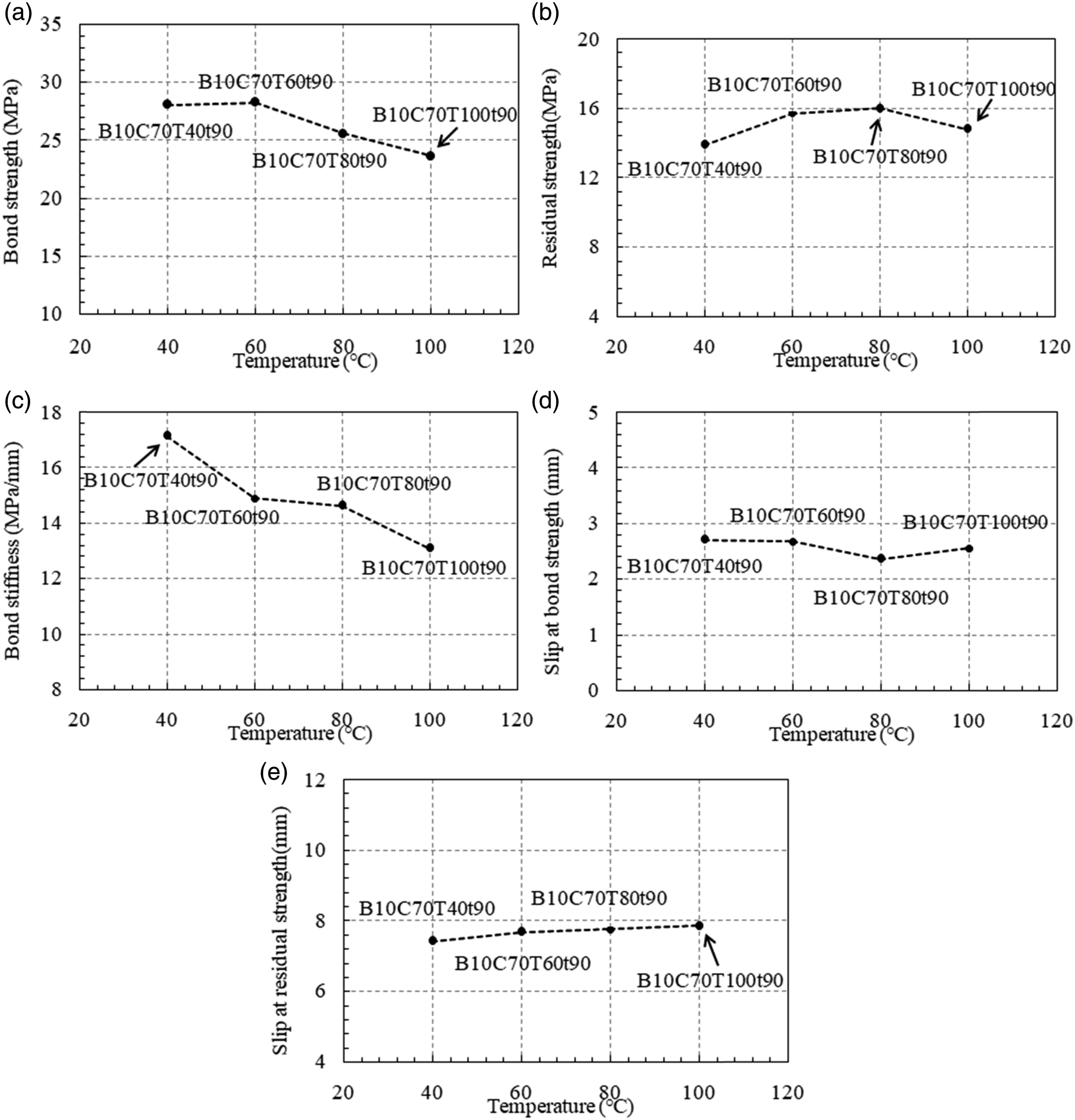
Effect of cycling times
Effect of cycling times on the bond behavior of pullout specimens exposed to the target temperature of 60°C is shown in Figure 10. Compressive strength of SSC exposed to 60°C and various cycling times is 61.9, 63.3, 65.7, 66.0 and 67.3 MPa for 30, 60, 90, 120 and 150 times of thermal cycles, respectively. As shown in Figure 10 (a), with the increase in cycling times, bond strength decreases and the changing rate speeds up. Since concrete strength slightly increased, the degradation of bond strength is mainly caused by the deterioration of BFRP and bar-to-concrete interface under thermal cycles. As discussed in Effect of target temperature, BFRP is degraded due to high temperature exposure and the alkaline environment. In this study, increase in cycling times leads to a longer exposure time of BFRP to high temperature. The increase in expansion/contraction cycles also further deteriorates the bonding surface between BFRP bar and SSC. With the increase in cycling times, the residual strength increases first and then drops down (Figure 10 (b)). The residual strength is controlled by the combined effect of the development of debonding along the bond length and the introduce of intact ribs in free end to resist the applied load. Figure 10 (c) shows a gradual decrease of the bond stiffness with the increase in cycling times. The degradation mechanism is similar as that for bond strength. As shown in Figure 10 (d), effect of cycling times on slip at bond strength is insignificant. The changing trend of the slip at residual strength is similar as that for residual strength, which first increases and then drops down with the increase in cycling times. Effects of cycling times on: (a) bond strength; (b) slip at bond strength; (c) bond stiffness; (d) residual strength; (e) slip at residual strength.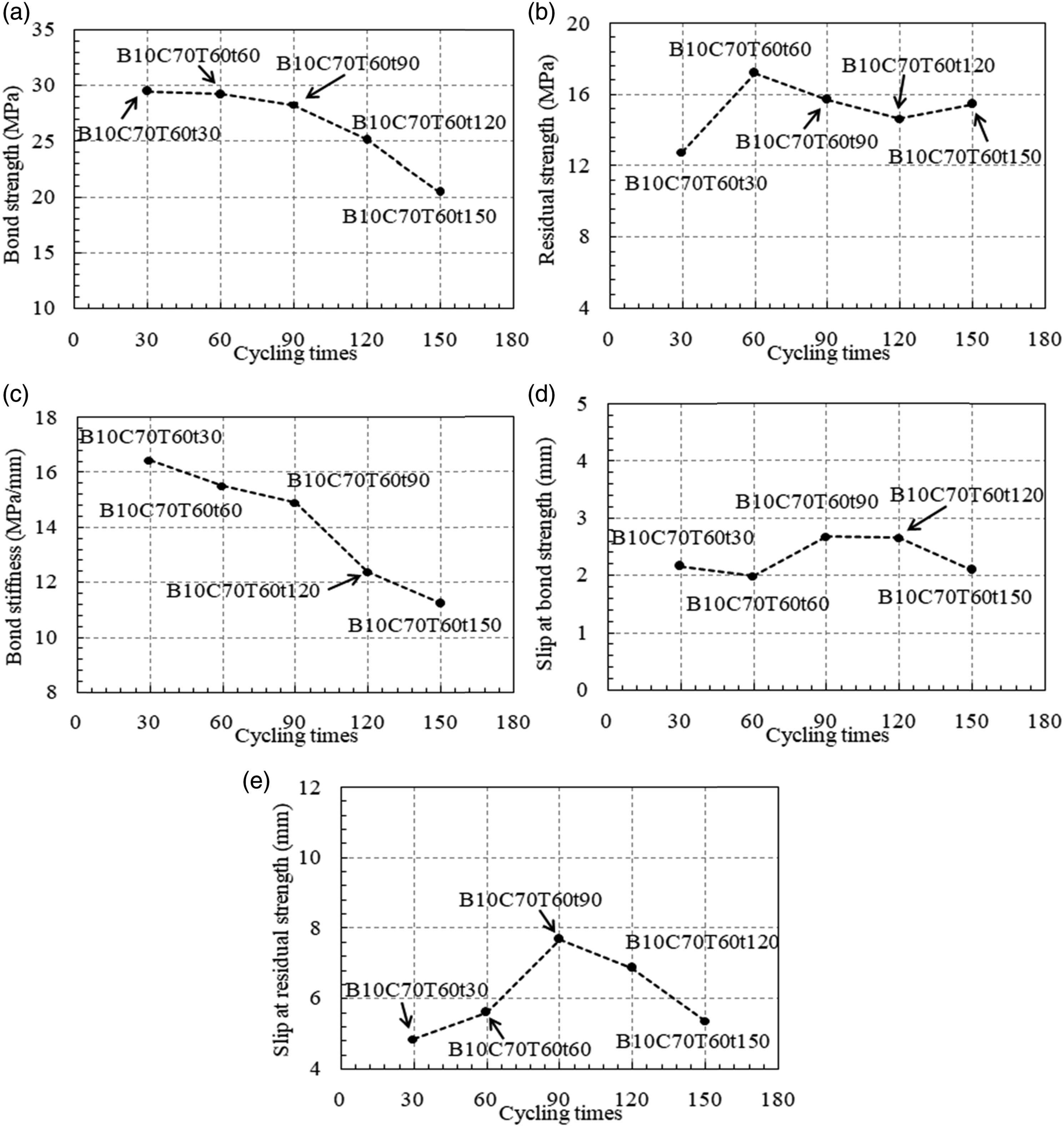
Degradation mechanism of daily temperature variations
As discussed in the previous Sections, degradation of bond in pullout specimens is mainly caused by the deterioration of BFRP bars. Scanning electron microscopy (SEM) was conducted to evaluate the microstructure of BFRP before and after thermal cycles and SEM images are shown in Figure 11. Figure 11 (a) shows the SEM image of unconditioned BFRP and Figure 11 (b) is the image of BFRP imbedded in SSC after standard curing. Slight damage in resin can be observed for specimen B8C70-N, which is owing to the alkaline environment of SSC, but basalt fibres are intact. As shown in Figure 11 (c), swelling of resin in the free end of BFRP bar is observed for specimen subjected to 40°C temperature variation for 90 times, which is probably caused by the moisture (70% humidity) environment [34] and thermal cycles. However, swelling of resin in the bonded part is insignificant but the damage in resin is more obvious (Figure 11 (d)). As shown in Figure. 11 (e) and (f), BFRP bar exposed to 100°C target temperature has more debris particles than BFRP bar exposed to 40°C. Comparing to Figure 11 (e), little resin is attached on fibres of the bonded part of BFRP bar (Figure 11 (f)), indicating a severer deterioration of fibre-to-resin interface. This leads to a significant drop of the interlaminar shear strength of BFRP bars. The difference in the degree of BFRP degradation in free end and bond part leads to the recovery of the bond stress after the first peak point in the bond stress-slip curves. By comparing Figure 11(g) to (j), increase in thermal cycles could worsen the bonding between fibres and resin, which agrees with the experimental observation of the drop of bond strength. As shown in Figure 11 (j), little resin is attached on fibres. Degradation of FRP in bonded part is severer than that in free part, which is probably due to the high alkaline environment of SSC. SEM images of BFRP bars.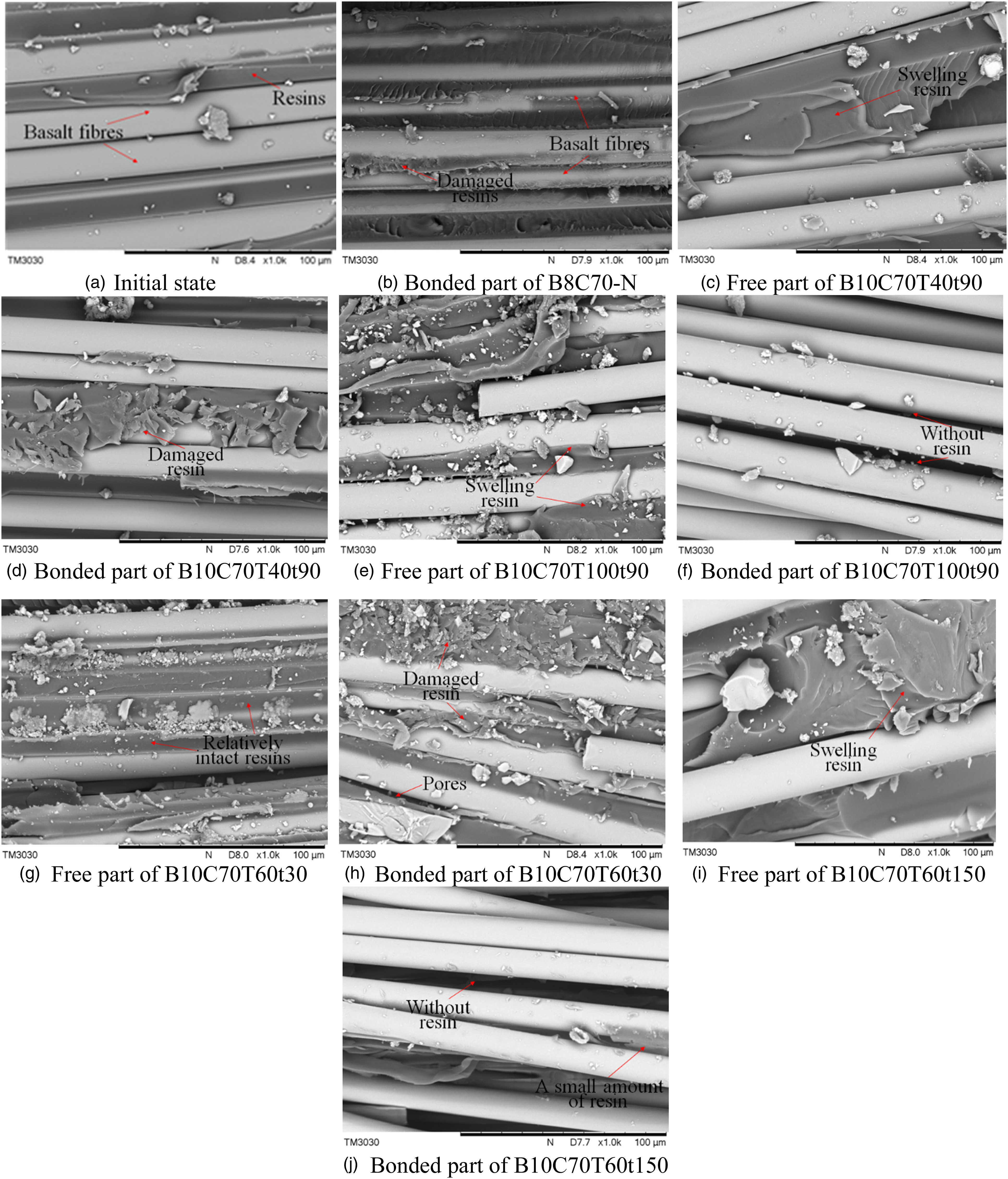
Bond mechanism between BFRP bar and SSC is illustrated in Figure 12. In general, the bond mechanism for unconditioned and conditioned specimens are similar, except degradations are introduced to BFRP bars and the bar-to-SSC interface by thermal cycles before pullout test. Bond between BFRP bar and SSC before pullout test is shown in Figure 12 (a). During the initial loading process, the applied force is resisted by the chemical adhesion between the bar and concrete (Figure 12 (b)). Thereafter, mechanical interlocking between bar and concrete develops, contributing to most of the bond stress. With the increase in slip and bond stress, cracks are formed at roots of ribs due to the shear stress (Figure 12 (c)). With further increase in applied force, shear failure occurs at the rib roots and concrete debris is formed due to the bearing force (Figure 12 (d)). The shear strength between fibers and resin seems to control the bond capacity between FRP bars and SCC. The successive shear failure at rib roots leads to a gradual decrease of the bond stress. As the free end of the BFRP bar is pulled into the concrete, a recovery of bond stress can be observed in this study owing to a re-development of the mechanical interlocking between the fresh ribs and concrete. For specimens after temperature variations, BFRP is degraded before pullout test and the shear strength between fibre layers and resin in FRP bar is weakened (Figure 12 (e)), which leads to a reduction of bond strength. Bond mechanism: (a) before test; (b) damage of cohesion; (c) initiation of cracks at rib roots; (d) shear failure of ribs; (e) degradation of BFRP due to thermal cycling.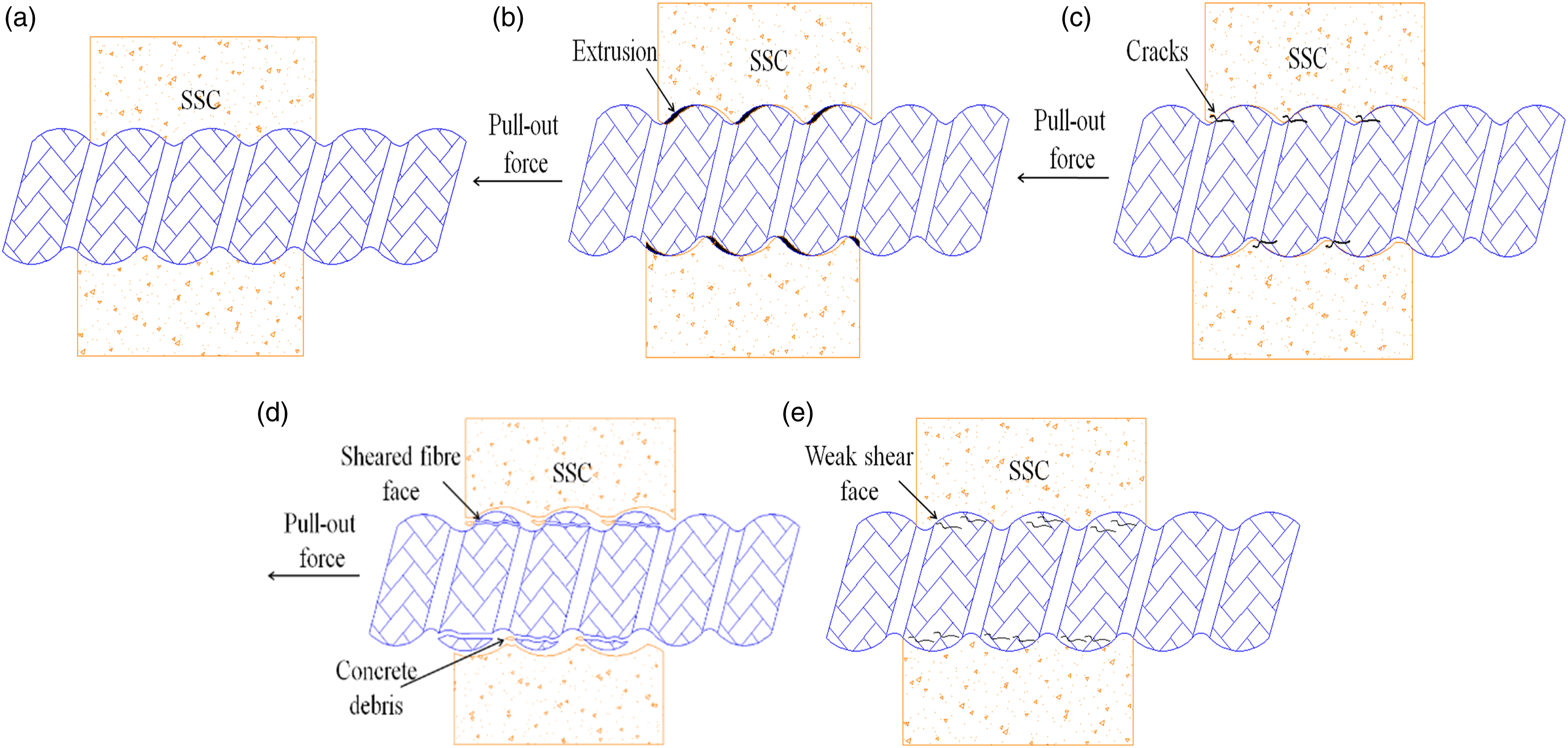
Theoretical model
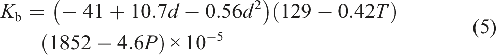
As discussed in Discussions, with the increase in bar diameter, bond strength, bond stiffness and residual strength increase first and then decrease. Slip at bond strength and residual strength increases with the increase in the summation of rib width and dent width (wr+wd). For specimens subjected to 90 times of thermal cycles, increasing the target temperature could reduce the bond strength and bond stiffness. However, the effect of target temperature on slip at bond strength and residual strength is insignificant. At a given target temperature (i.e. 60°C), increasing in thermal cycling times reduces the bond strength and bond stiffness. However, the residual strength and slip at residual strength increase first and then drop down with the increase in cycling times and its effect on slip at bond strength is insignificant. By regressing the experimental data available in this study, formulas are proposed to predict the bond strength (τb), slip at bond strength (sb), slip stiffness (Kb), residual strength (τc) and slip at residual strength (sc):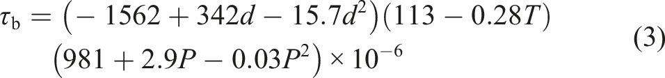


In this study, the recovery of bond stress after peak point is caused by the pull-in of the free end of BFRP bar. However, the bond stress recovery is not applicable for FRP bar reinforced members. Therefore, it is assumed that the bond stress is equal to the residual strength if the slip exceeds sc. Based on the authors’ past studies (Xiong et al., 2021a, 2021b) on bond behavior of unconditioned specimens, bond stress-slip (τ-s) relationship of BFRP bar reinforced SSC after thermal cycles could be predicted by:
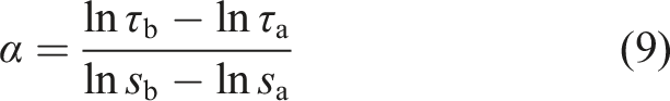

Figure 13 shows a comparison between the predicted and experimental bond stress-slip curves. In average, the prediction error for τb, sb, Kb, τc and sc is 1.11%, 6.80%, −0.56%, 1.32% and 4.01%, respectively. The predicted curves generally match well with the experimental curves before reaching the slip at residual strength. As explained previously, the prediction cannot capture the recovery of bond stress, which is a unique phenomenon for specimens investigated in this study. In general, the proposed theoretical model could predict the τ-s relationship of BFRP bar reinforced SSC subjected to temperature variations with acceptable accuracy. Comparison between the experimental and predicted bond stress-slip curves.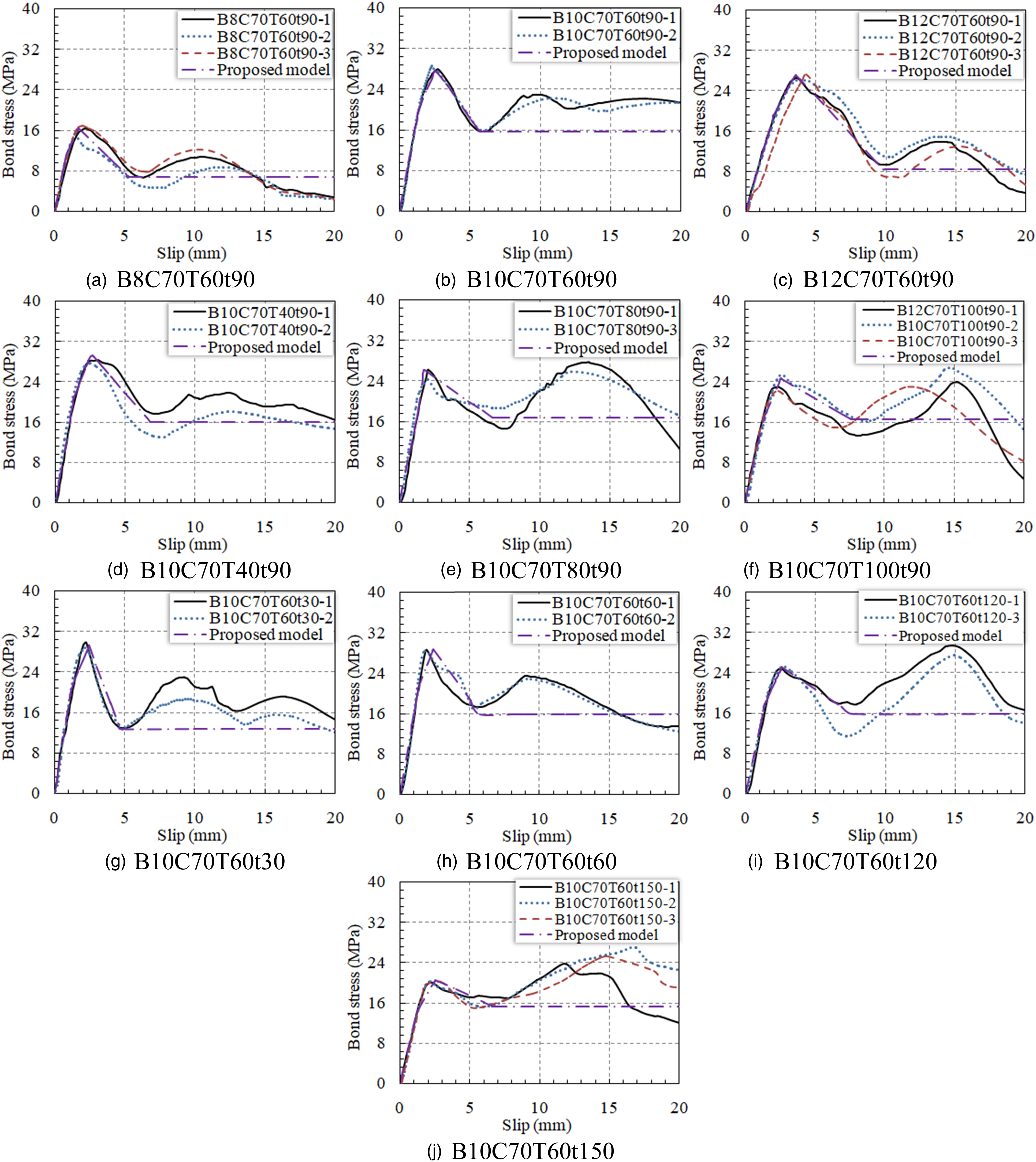
Conclusions
This paper mainly investigates the effect of temperature variations (i.e. target temperature and thermal cycling times) on the bond behavior of BFRP bar imbedded in SSC. Conclusions are drawn as following: (1) For both unconditioned pullout specimens and specimens subjected to temperature variations (40–100°C and 30–150 times), the debonding failure modes were similar, which was the shear failure of bar ribs. By increasing the target temperature and cycling times, fibre floccules appeared on bar surface and the color of bar-to-SSC interface changed from gray to brown. (2) Bond stress-slip curve is consisted of an ascending part up to bond strength, a gradual descending part down to the residual strength, a bond stress recovery part and another descending part. The recovery of bond stress is mainly caused by the contribution of the ribs in the free end of BFRP bars, which are pulled into concrete. (3) Increasing the target temperature from 40°C to 100°C for specimens subjected to 90 times of thermal cycling leads to an increase of bond strength and bond stiffness, whereas the residual strength increases first and then drops. Effect of target temperature on the slips at bond strength and residual strength is insignificant. With the increase in cycling times (i.e. from 30 to 150 times), bond strength and bond stiffness decrease but its effect on the slip at bond strength is insignificant. (4) Based on mechanical test results and SEM analysis, deterioration of BFRP material is the main reason to the degradation of BFRP bar-to-SSC bonding. (5) Theoretical model is proposed to predict the bond stress-slip relationship of BFRP bars in SSC under temperature variations and the prediction matches well with the experimental results.
Footnotes
Declaration of conflicting interests
The author(s) declared no potential conflicts of interest with respect to the research, authorship, and/or publication of this article.
Funding
The author(s) disclosed receipt of the following financial support for the research, authorship, and/or publication of this article: The authors gratefully acknowledge the financial support provided by the National Natural Science Foundation of China under Grant No. 12032009 and No. 12002091.