
Abstract
Modular steel buildings (MSBs) can meet the needs of building industrialization and have been developed in many countries. The inter-module connection is crucial to the overall performance of MSBs. An inter-module connection with bolt and shear key fitting was proposed in this paper, which is convenient for the on-site erection of the steel modules. The flexural performance of the connection was studied. Static tests were carried out to study the contribution of the key load-bearing components to the flexural performance of the novel connection. A finite element model was then proposed and verified, by which a parametric analysis to study the effects of the key components was conducted. It is found that the parameters significantly affecting the flexural performance of the connection include the diameter of the bolt and the thickness of the bottom plate. The results also showed that the contribution of the shear key to the flexural performance of the connection could be ignored. The flexural performance of multi-module connection was studied, and the results revealed that the multi-module connection can be designed as multiple two-module connections. Formulas for calculating the flexural capacity and rotational stiffness of the connection were finally proposed and verified.
Keywords
Introduction
The modular steel building (MSB), built by stacking modules on-site, is one of the most integrated prefabricated buildings. It can achieve the goal of better quality control, less construction time and being more environmentally friendly by recycling modules (Luo et al., 2019). The disadvantage of MSBs is mainly the limited structural span caused by the module’s size (Lacey et al., 2018). Due to the characteristics of fast construction speed and mass production of modules, various MSBs have been used in diverse applications such as hotels, schools and military facilities (Sanches et al., 2018). However, with the rapid development, the lack of design guidance and specification of MSB remains one main concern.
The steel modules used in the MSB are manufactured off-site, transported and assembled on-site. According to the force-transferring path, steel modules can be divided into corner-supported modules and continuously supported modules (Lacey et al., 2018). The corner-supported steel modules have a better vertical capacity and are more applicable in high-rise buildings (Chen et al., 2017b). The steel modules are divided into MSB modules and light steel frame modules according to the section of beams and columns (Lacey et al., 2018). For light steel frame modules, the section of beams and columns is wide section. So the light steel frame modules are light in weight and suited to low-rise buildings. While the MSB modules have high strength and suitable for high-rise buildings, for the section of beams and columns is hollow section. In addition, the hollow section has a closed internal space, which is convenient for welding with the corner of module and fit for more types of inter-module connections. Therefore, in most of the research on the inter-module connections, the section of beams and columns is hollow section.
Due to the importance of inter-module connection in erection efficiency and load transfer for MSBs, various inter-module connections have been proposed and studied. Chen et al. (2017b) proposed a new type of design with beam-to-beam connections and studied its flexural performance and seismic behavior. Results revealed that beams and connections had independent and individual bending behaviors. Annan et al. (2009a, 2009b) evaluated the hysteretic characteristics of MSB, using welding as the vertical connections and field-bolting of clip angles as horizontal connections between modules. By comparing the performance between a regular braced frame and a modular braced frame, they concluded that the detailing requirements of the system need to be incorporated in the design of the modular braced frame. Chen et al. (2017a) investigated the seismic performance of a modular frame with pretension inter-module connections, in which the columns are vertically connected by pre-stressed strands. It was found that the pretension assembled framed modular system had different internal stress distribution from the traditional one. Chen et al. (2020) also studied the tensile and shear performance of a rotary inter-module connection. The performance of the critical components was investigated under tensile and shear loads, and simplified calculations were developed. Lee et al. (2017) proposed a new inter-module connection to form a rigidly connected modular system and verified the seismic performance of the proposed system. The results showed that the maximum resisting force of the proposed connection exceeded the theoretical parameters. A splice connection (Li et al., 2019; Lyu et al., 2021) was studied in full-scale corner-supported modular building. The proposed connection was sufficient to transfer the vertical load and had an acceptable tolerance for initial imperfections. Choi et al. (2016) adopted a bolted connection with an access hole opening at the end of the column in nonlinear static analyses of modular structures. It was found that the modeling of overlapped elements and the rotational behavior of connections can influence the structure’s lateral stiffness. Sendanayake et al. (2021) proposed a novel steel inter-modular connection and studied the performance of the connection under monotonic and cyclic lateral loads. The results revealed that the connection can display superior dynamic behaviour. Dhanapal et al. (2020) introduced a unique cast-steel connector, which was studied through full-scale tests. The study concluded that the connection can safely carry the design loads. These connections mentioned above include the following types: bolted, welded, pretensioned, and concreted. Welded and concreted connections (Annan et al., 2009a, 2009b) have better stiffness but cannot take advantage of the detachability of MSBs. Although there are already several connection types and relevant research for bolted connections (Chen et al., 2020; Choi et al., 2016; Lee et al., 2017; Li et al., 2019; Sanches et al., 2018), the problems of weakening members' sections and sensitivity to installation errors are still unsettled. Pretensioned connections (Chen et al., 2017a) possess excellent stiffness and strength but have high requirements for on-site construction and are prone to slip. Therefore, more reasonable connections, which have sufficient capacity and on-site construction convenience, need to be proposed (Dai et al., 2019).
This paper proposed an innovative inter-module connection with a bolt and shear key fitting to solve the existing problems mentioned above. The proposed connection can transfer the vertical loads and horizontal actions separately with independent components, which is easy for analysis and design. In addition, the inter-module connections at different locations can be installed inside the module and have a high tolerance to manufacturing and hoisting errors of the modules. The flexural performance of the novel connection was studied in this paper. The flexural performance is one of the properties of the inter-module connection, which is of great significance to the structural safety of MSBs during normal operation and integrity in emergency occasions (Lawson and Richards, 2010; Lawson et al., 2008).
The static monotonic tests were conducted to study the flexural performance of the proposed connection, and the stress distribution of the key components was obtained. A finite element model was then presented to conduct the parametric study, by which main parameters affecting the connection’s flexural performance and different failure modes were obtained. Multi-module connections were studied by the verified finite element model. The formulas for calculating the flexural capacity and rotational stiffness of the connection were proposed, which were validated against the experimental results and can be used as a design guide.
Configuration of the proposed inter-module connection
The details of the proposed connection at the corner are shown in Figure 1(a). The connection is composed of three components: connecting plate (green part), bolt (red part), and steel castings (blue and yellow part). The beams and columns are welded to the steel castings. The connecting plate is located between the steel castings. Two shear keys are welded on both sides of the connecting plate. The shear keys will be embedded in the shear keyhole without any connection, indicating that the shear key can only transfer the horizontal load. The bearing-type bolt connects the adjacent modules through the slotted hole. Details of the proposed connection. (a) Inter-module connection with bolt and shear key fitting, (b) Ceiling steel casting.
The detail of the ceiling steel casting is shown in Figure 1(b). The ceiling steel casting is composed of an L-shaped hollow box (blue part) and a triangular plate (yellow part). The slotted hole is opened on the triangular plate, and the shear keyhole is opened on the bottom plate of the L-shaped box. The thickness of the triangular plate is the same as that of the bottom plate. The plates of the L-shaped except for the bottom plate are called side plates. The structure of the floor steel casting is similar to that of the ceiling steel casting.
The proposed connection has the following advantages in mechanical performance and on-site erection. Firstly, the connection separates the vertical load-bearing components from the horizontal ones. There is no connector between the shear key and the steel castings, so the shear key cannot transfer tension and bending moment. Since the shape of the bolt hole is semi-slotted, it is hard to form the shear plane between the bolt and plates. Therefore, under the action of horizontal force, it is difficult for the bolt to transfer the horizontal force before the shear key is broken. Secondly, the bolt holes are opened on the triangular plate instead of the beam and column, ensuring the integrity of the members in the steel module. And thirdly, the bolts are located inside the module so that the insufficient construction space problems can be settled. Therefore, the connection can be completed conveniently inside the module through the reserved opening at various positions.
Experimental study
Materials and specimen
Material properties.

The flexural specimen is shown in Figure 2. The bottom column, top column and fixed beam were welded to the connection. The loading beam was welded to the top column through stiffeners. Dimensions of the steel castings and connecting plate are shown in Figure 3, and the dimensions were determined by preliminary theoretical and numerical analysis before the experiment. The thickness of the bottom plate of steel castings Specimen. (a) Ceiling steel casting (b) Floor steel casting (c) Connecting plate. Dimensions of connection’s components (unit in mm).
Test setup
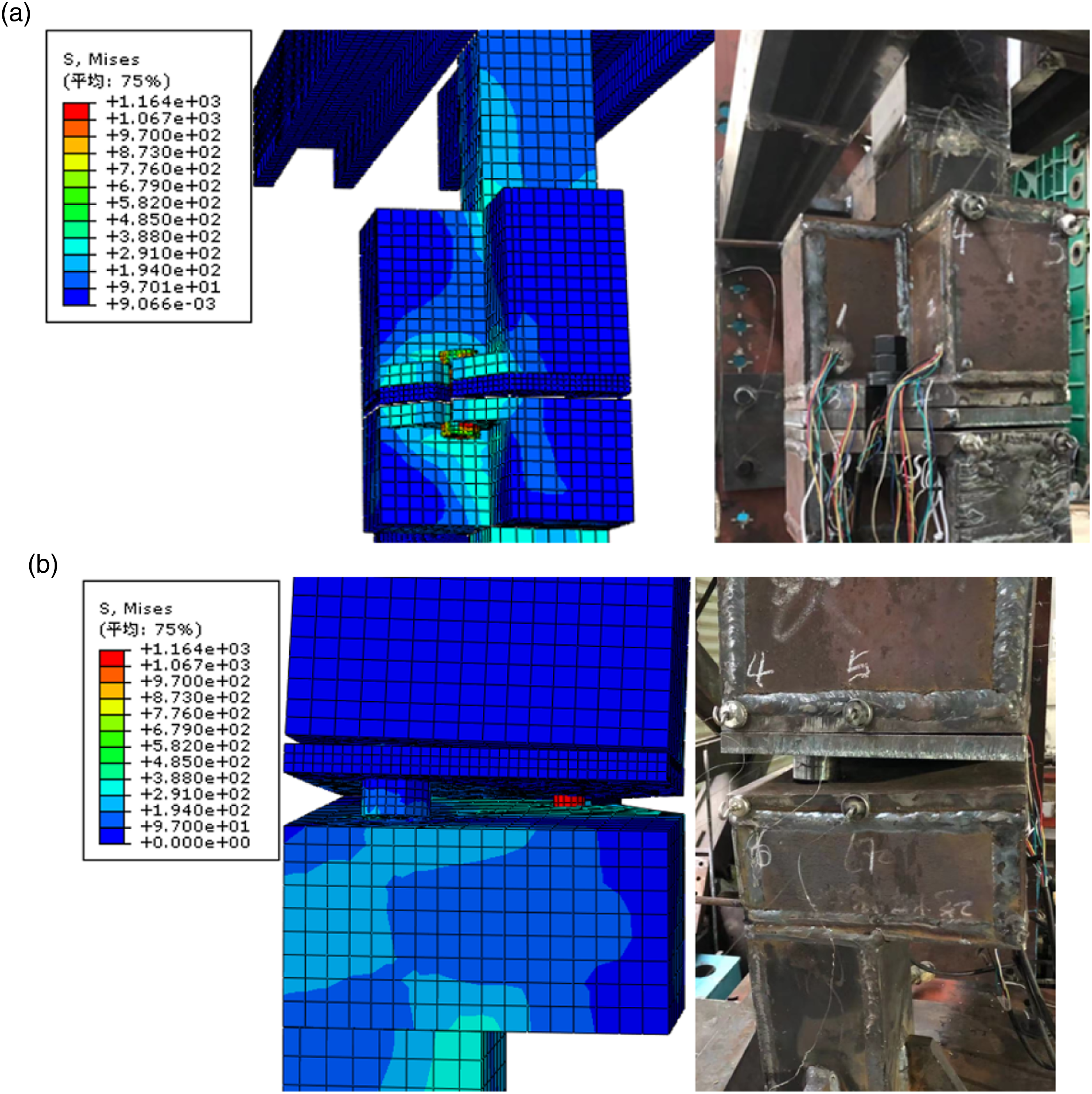
The test setup is shown in Figure 4(a), which includes the specimen, 2000 kN horizontal actuator, cantilever support and reaction frame. The specimen is fixed on the reaction frame. The top view of the test setup is shown in Figure 4(b), the out-of-plane displacement of the specimen is restricted by the cantilever support, and the specimen can only move within the red frame. As shown in Figure 4(e), the cantilever support consists of an end plate, stiffener, pedestal and two cantilever beams. The loading head of the actuator is close to the end of the loading beam without any connector. As shown in Figure 4(c) and (d), 2 mm plates made of PTFE (poly tetra fluoroethylene) are set in the gap between the actuator and the loading beam, as well as between the cantilever support and the top column. Two specimens were tested: one specimen was loaded along Test setup. (a) Test setup, (b) Top view of the test setup, (c) Photograph of the test setup, (d) PTFE plates between the cantilever support and specimen, (e) Cantilever support.
The measurement arrangement of the experiment is shown in Figure 5. Displacement meters BD1∼BD3, BD4∼BD5 and BD6∼BD7 are used to measure the horizontal displacement of the loading beam, floor steel casting and ceiling steel casting, respectively. Strain gauges BS1∼BS2 and BS7∼BS8 are mounted vertically at the side plates close to the triangular plates, and strain gauges BS3∼BS6 are located at the triangular plates. Strain gauge BS9 is intended to measure the tensile strain of the bolt. Measurement arrangement.
Experiment results and discussion
Test loaded along
direction
Phenomena in the test loaded along
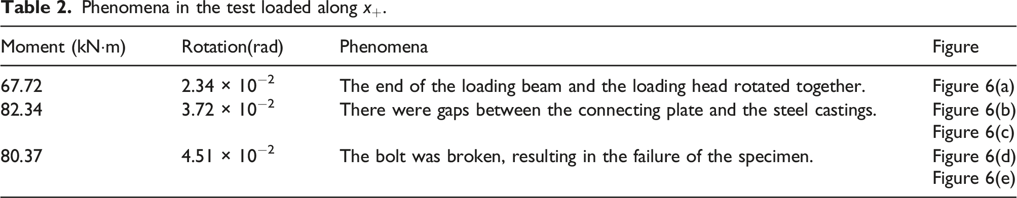
Deformation state and failure behaviors in the test loaded along
The load-strain curves are shown in Figure 7. According to the data measured by the strain gauges on the side plates, as shown in Figure 7(a), the side plates were in the elastic stage during the whole loading process. As shown in Figure 7(b), when the load reached 68.3 kN, the triangular plate of floor steel casting began to yield. And the strain close to the gap of the same triangular plate developed faster. The strain of bolt kept increasing until the bolt failed, as shown in Figure 7(c). When the bolt failed, the tensile stress at the strain gauge BS9 was 920.67 MPa. Calculated according to the pitch diameter of the thread, the tensile stress at the thread was 1090.56 MPa, which had exceeded the yield strength of the bolt. The load-strain curves measured by strain gauges. (a) Strain of the side plates, (b) Strain of the triangular plates, (c) Strain of the bolt.
The moment-rotation curve of the specimen loaded along 

Test loaded along
direction
Phenomena in the test loaded along
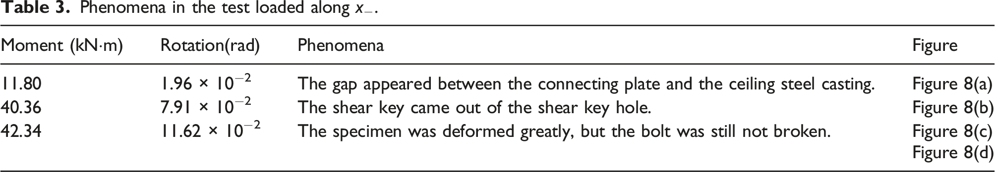

Deformation state and failure behaviors in the test loaded along
The load-strain curves measured by strain gauges are shown in Figure 9. The strain of the side plates increased linearly except for the BS2. When the load was less than 30 kN, the side plate at BS2 was under compression; when the load was greater than 30 kN, the side plate at BS2 was under tension. This showed that in the early stage of loading, the axis of rotation was not at the point C-. When the load increased to about 30 kN, the axis of rotation moved to point C-. Similar to the test loaded along The load-strain curves measured by strain gauges. (a) Strain of the side plates, (b) Strain of the triangular plates, (c) Strain of the bolt.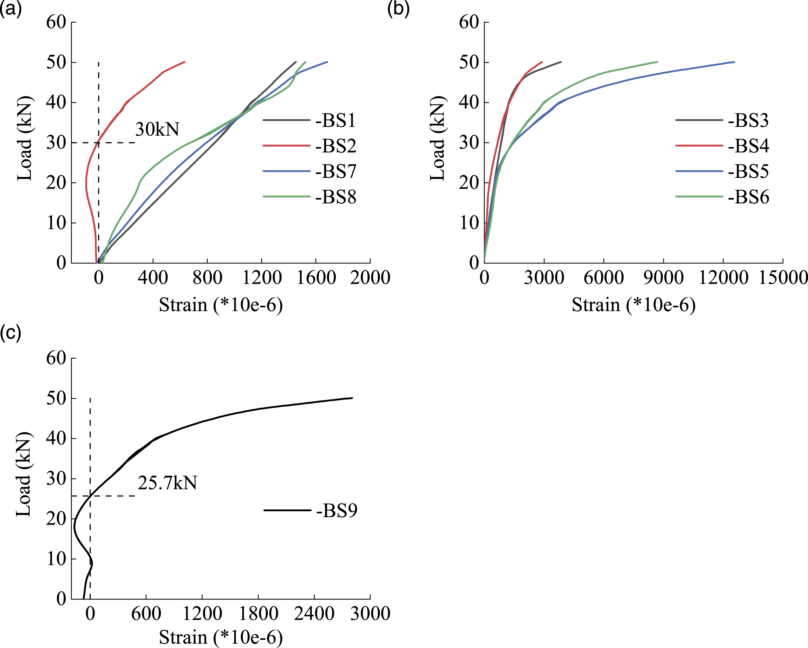
The moment-rotation curve of the specimen loaded along Moment-rotation curve of the specimen.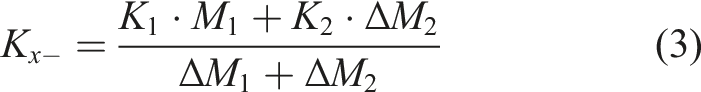
In this part, the flexural performance of the connection was studied through monotonic experiments. Flexural capacity, initial rotational stiffness and key components were obtained. The arm of force at the shear key is small, and the pull-out of the shear key did not lead to a significant drop in flexural capacity. It can be found that the shear key is not the main moment-bearing component. And the expected failure mode of the connection is the yield of the bolt, which is convenient to replace.
Numerical study
Finite element model
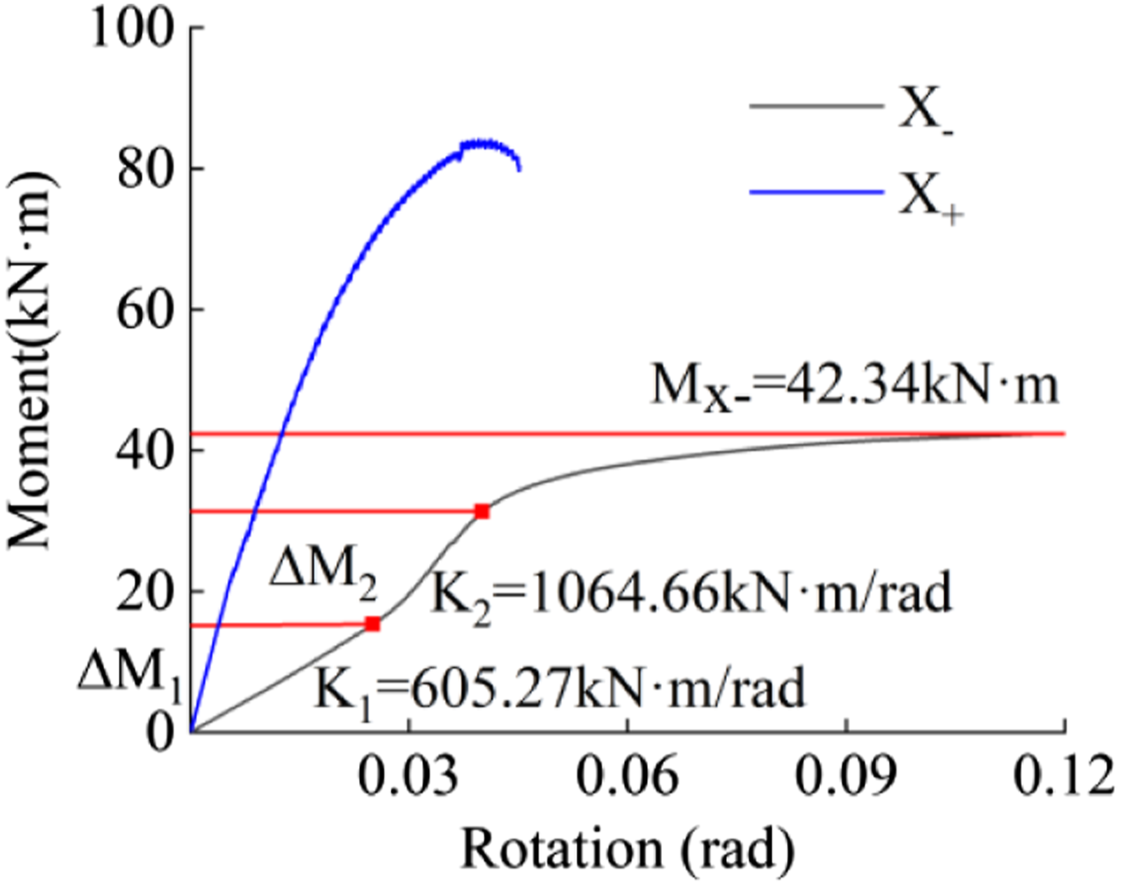
A finite element model was proposed to study further the flexural performance of the proposed connection by finite element software ABAQUS. The meshing result and boundary conditions are shown in Figure 11. The properties of the material and the dimensions of the parts in the FE model were the same as those in the tests. For the material model, the trilinear elastic model was adopted. All elements of the model used the eight-node linear hexahedral reduction element C3D8R. The welding connection was simulated by “tie”. The displacement load was applied to the end of the loading beam. Finite element model.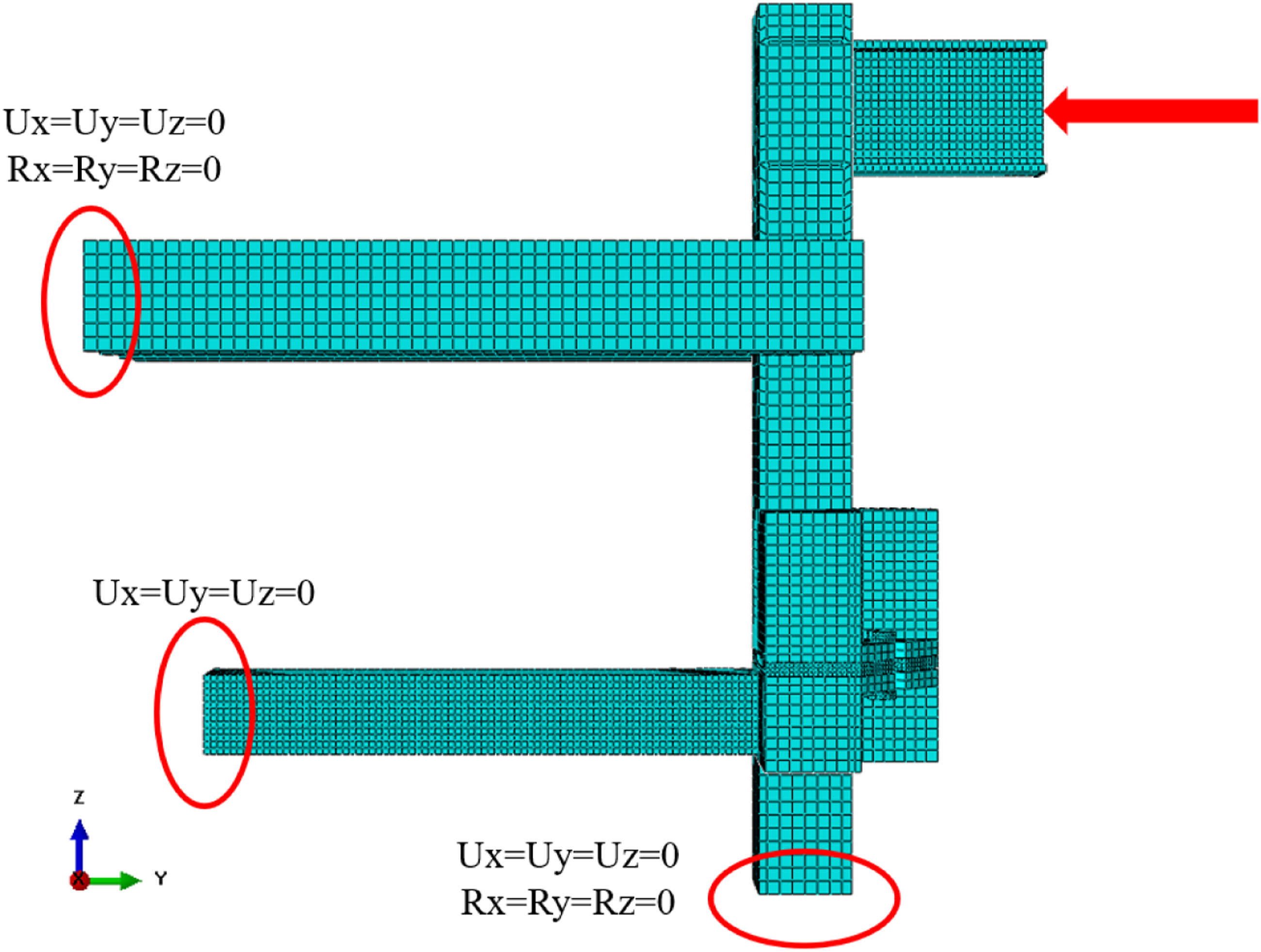
In order to verify the rationality of the model, the load-displacement curve and failure mode of the numerical study were compared with those in the test. The load-displacement curve of the finite element model is shown in Figure 12. At the initial stage of loading along Load-displacement curve of the finite element model. (a) Test loaded along Comparison of numerical and analytical results with experimental results. Stress contours of connection. (a) Model loaded along 
Parametric study
The value of parameters.
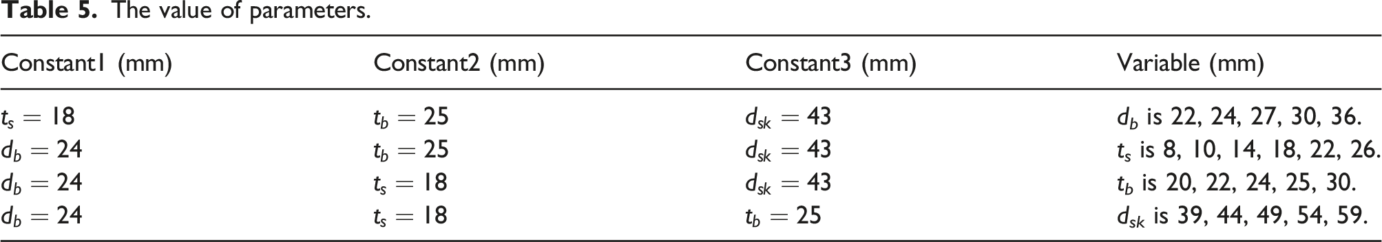
Moment-rotation and capacity curves of different parameter values are shown in Figure 14. For Moment-rotation and capacity curves of different parameter values. (a) The diameter of the bolt 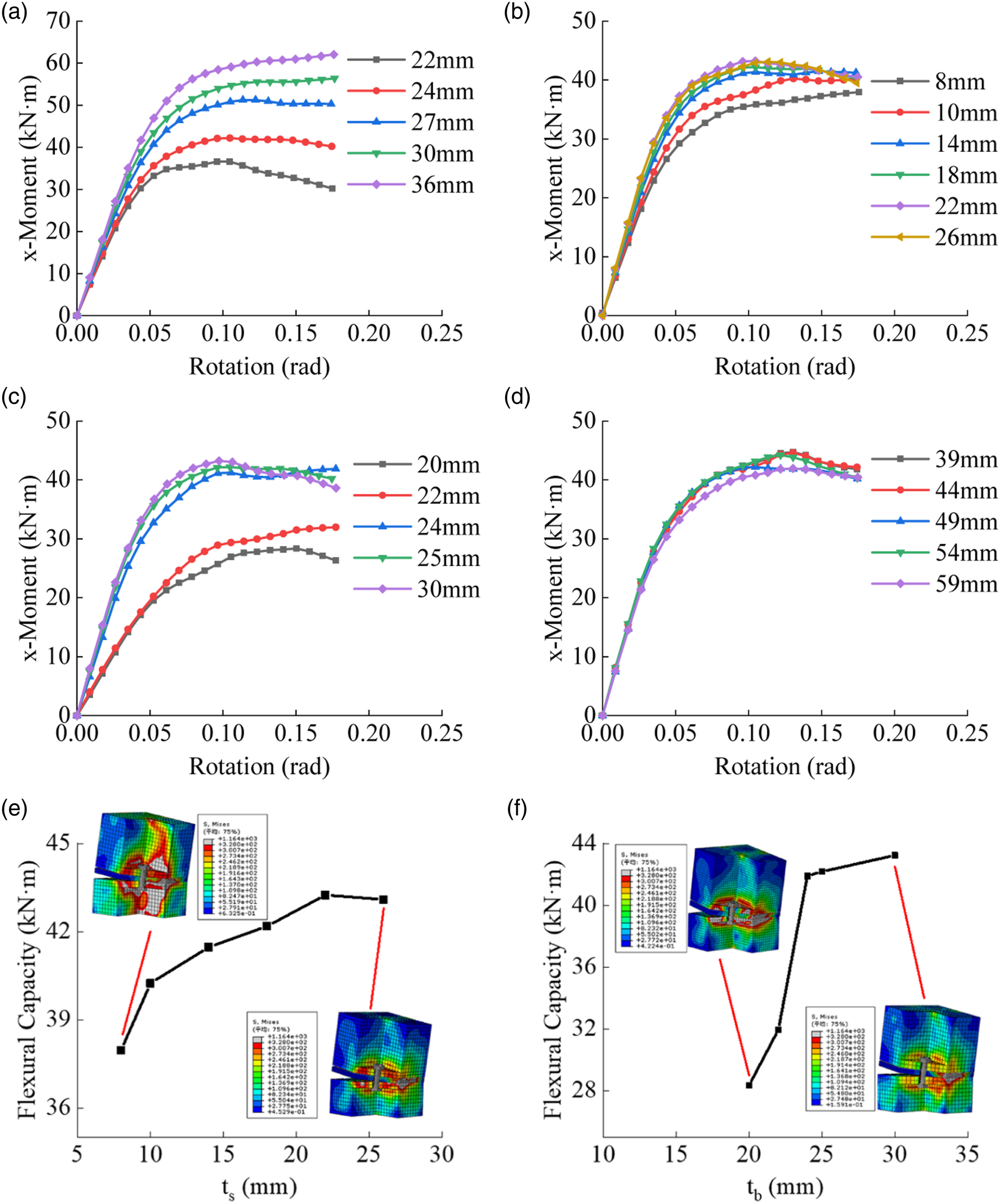
As shown in Figure 14(e), when
Connection between multiple modules
The previous tests and analyses are all for two-module connections. For multi-module connections, the connections connect adjacent modules by sharing the same connecting plate. In order to study the influence of sharing the same connecting plate on the performance of multi-module connections, a four-module connection is analyzed by numerical method. As shown in Figure 15(a), four modules A, B, C and D are connected by connection A and B. The verified finite element model is used to study the flexural performance of the four-module connection in the direction shown in Figure 15(b). The comparison of moment-rotation curves between the four-module connection and the two-module connection is shown in Figure 15(c) and (d). The results reveal that the flexural performance of each connection in the four-module connection is basically the same as that of the two-module connection. And the difference is smaller when loaded along the Y direction. It can be concluded that each connection in the multi-module connection can be analyzed and designed as a two-module connection. Connection between multiple modules. (a) Four-module connection, (b) Direction of loading, (c) Loaded along X, (d) Loaded along Y.
In this section, a finite element model was proposed to simulate the flexural performance of the connection. By comparing with the results in the test, the finite element model was verified. The proposed model was used for parametric analysis to obtain the parameter affecting the flexural capacity and rotational stiffness of the connection. The diameter of the bolt
Analytical study
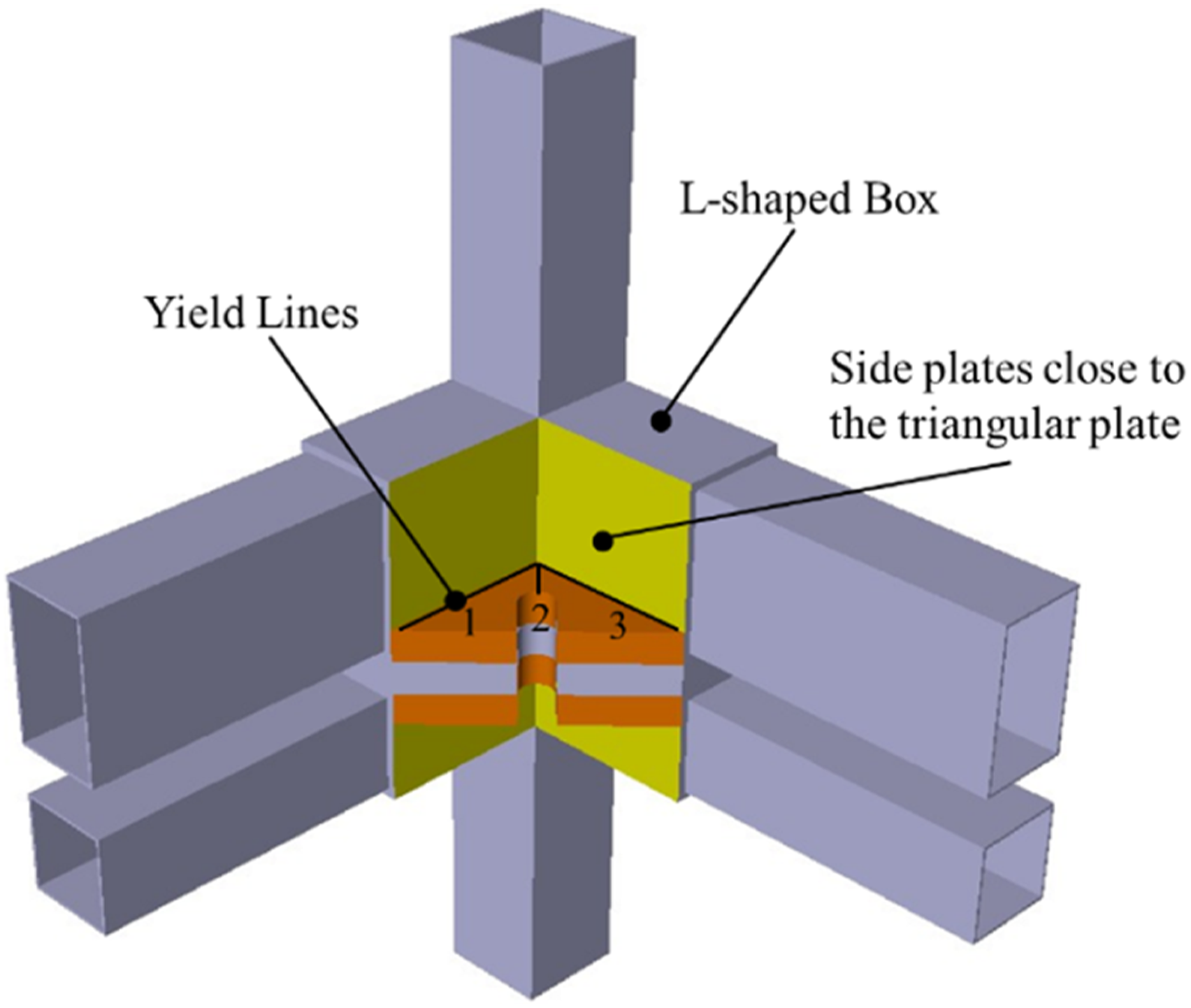
Based on the results of the experiment and numerical study, the main parameters affecting the flexural performance of connection and different failure modes were obtained. These parameters are used to calculate the flexural capacity and rotational stiffness of the connection in the experiment. Conservative assumptions were proposed as follows a. For the side plates of the steel casting, only the side plates close to the triangular plate is considered to transfer the moment. b. According to the stress distribution in the numerical results, it is assumed that the distribution of yield lines in the triangular plate is shown in Figure 16. c. Ignore the compression and tensile deformation of the side plates in the experiment. Schematic diagram of calculation of flexural capacity.
Flexural capacity
The formulas of flexural capacity for different failure modes are analytically derived and given below.
1. Failure mode 1: Yield of the bolt
When the connection is damaged due to the yield of the bolt, the formula for calculating the flexural capacity of the connection is given by
2. Failure mode 2: Yield of side plates
As shown in Figure 16, according to the stress contours of the finite element model, it’s assumed that when the L-shaped box is subjected to moment, only the side plates close to the triangular plate (the yellow area) transfer the load. The formula for calculating the flexural capacity 
3. Failure mode 3: Yield of triangular plate
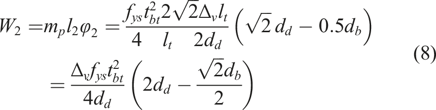
The yield line theory is used to calculate the tension of the bolt when the triangular plate yields. According to the results of the parametric analysis, the stress distribution of the triangular plate at yield is shown in Figure 17. The yield area of the triangular plate is roughly shown by the blue line. According to the blue line in Figure 17, three assumed yield lines are shown in Figure 16. Based on the principle of virtual work, the tension of the bolt when the triangular plate yields is given by stress distribution of the triangular plate at yield.


And the flexural capacity controlled by the triangular plate is given by
By summarizing the above three failure modes, the tensile capacity of the connection 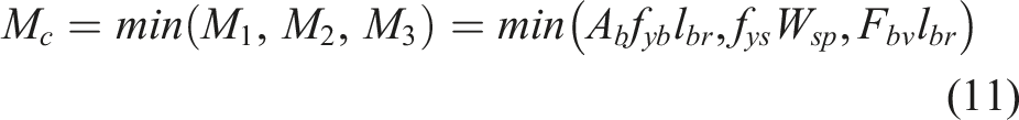
Rotational stiffness
According to Eurocode 3: Design of steel structures-Part1-8: Design of joints (BS EN 1993-1-8:2005, 2005), the rotational stiffness of the connection in the test is calculated by the component method. As shown in Figure 18, according to the component method, the connection can be divided into tension area (red line) and compression area (green line). The components of the tension area include the bolt, triangular plates and side plates away from the rotation axis (Side Plates 1). The components of the compression area include the connecting plate and side plates close to the rotation axis (Side Plates 2). Since the tensile and compressive stiffness of the side plates and connecting plate are much greater than the tensile stiffness of the bolt and the flexural stiffness of the triangular plate, the tensile and compressive stiffness of the side plates and connecting plate are ignored. According to Eurocode 3: Design of steel structures-Part1-8: Design of joints (BS EN 1993-1-8:2005, 2005), the rotational stiffness of the connection is given by Schematic diagram of component method.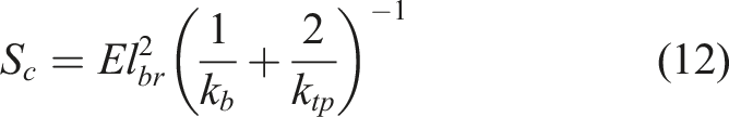

The triangular plate can be regarded as a stiffened column flange. The bolt is adjacent to the stiffener, and the bolt hole is semicircular. According to Eurocode 3: Design of steel structures-Part1-8: Design of joints (BS EN 1993-1-8:2005, 2005), the stiffness coefficients are given by

Validation
In the process of proposing the theoretical formulas, many conservative assumptions were made. The results obtained by the theoretical study are compared with the results in the test, as shown in Table 4. Since the theoretical calculation method is conservative, the flexural capacity and rotational stiffness obtained in experiment are larger.
In addition, the results of theoretical formulas are compared with the results of parametric analysis. As shown in Figure 19, the theoretical formula can safely calculate the capacity of the connection. For the diameter of the bolt, when Comparison of theoretical results and parametric analysis. (a) The diameter of the bolt 
Combining the conclusions of the experimental and numerical study, formulas for calculating the flexural capacity and rotational stiffness were proposed. The proposed formulas were validated by comparison with results in the test and parametric analysis. And it is proven that the formulas can be used to design the connection and obtain the desired failure mode.
Conclusions
This article proposed an inter-module connection with a bolt and shear key fitting and investigated the flexural performance of the connection. The main conclusions are summarized as follows: (1) The proposed inter-module connection separates the vertical load-bearing components and the horizontal load-bearing components with the bolt resisting the tension and moment and the shear key resisting the shear force, which simplify the configuration of the connection and ease the erection of steel modules. The connection can be installed in various locations through the reserved opening and has a high tolerance to installation errors. (2) By experimental research, the stress development of key components and failure mode of the specimen were obtained. It is found that the shear key contributed little to the flexural performance of the specimen, for the pull-out of the shear key did not lead to a significant drop in flexural capacity. (3) A finite element model was built and validated to simulate the flexural performance of the connection. The parametric study was conducted by the proposed model, and the parameters affecting the flexural performance and different failure modes were obtained. The diameter of the bolt (4) Based on the experimental and numerical study, analytical formulas for calculating the flexural capacity and rotational stiffness were proposed. The results obtained by the formulas were compared with experiment and parametric analysis. It can be concluded that the formulas can be used to guide the flexural design of the proposed connection safely and guarantee the expected failure mode.
Footnotes
Declaration of conflicting interests
The author(s) declared no potential conflicts of interest with respect to the research, authorship, and/or publication of this article.
Funding
The author(s) disclosed receipt of the following financial support for the research, authorship, and/or publication of this article: The research work presented hereinabove was supported by the National Key Research and Development Program of China (Project No.2017YFC0703803-04) and the National Science Foundation for Young Scientists of China (Grant No.51808068).