
Abstract
Ultra-high performance concrete (UHPC) is being increasingly used as a thin overlay for deficient normal strength concrete (NSC) structural elements. Compared to reinforced NSC elements, hybrid NSC-UHPC elements have two stages' structural behaviour under high shear load before failure: monolithic action followed by a composite mechanical action. The composite mechanical action gives to hybrid elements a structural hardening capability after the occurrence of a diagonal shear crack and is not yet considered by most design standards. Two analytical models for hybrid elements under shear load are thus proposed to predict the shear resistance V R of the monolithic action and to predict the structural hardening resistance V Rsh of the composite mechanical action. The shear resistance model integrates the UHPC contribution in the estimation of the tensile strain at mid-height cross-section according to the general method of the Canadian code. The structural hardening behaviour is reproduced with a strut-and-tie system with plastic hinges, where the failure is controlled by the crushing of a concrete strut. Predictions of the proposed models are in very good agreement with 31 hybrid elements experimental results retrieved from the literature.
Keywords
Introduction
Ultra-high performance concretes (UHPC) feature minimum compressive strength of 120–150 MPa, minimum tensile strength of 5–7 MPa and a tensile strain hardening behaviour around 2000 µε (Naaman, 2008; AFGC, 2013; CSA, 2018; Eide and Hisdal, 2012; Haber et al., 2018). Such improved mechanical properties compared to normal strength concrete (NSC), strongly favour its utilization as thin overlay for rehabilitating or strengthening purposes, which is a growing field of application (Brühwiler, 2019; Brühwiler and Denarié, 2013; Guingot et al., 2013; Denarié et al., 2013). Through this concept, many experimental campaigns were realized to study the bending behaviour of hybrid NSC-UHPC elements (Habel, 2004; Makita, 2014; Oesterlee, 2010; Wuest, 2007; Al-Osta et al., 2017; Denarié et al., 2003; Lachance et al., 2016; Noshiravani and Brühwiler, 2013; Paschalis et al., 2018; Prem and Murthy, 2016; Safdar et al., 2016; Zingaila et al., 2017; Pharand, 2022; Yin et al., 2017). However, only a few (Pharand and Charron, 2022a; Sine et al., 2022; Noshiravani and Brühwiler, 2013; Ji and Liu, 2020; Yin et al., 2017) specifically studied the shear behaviour of hybrid NSC-UHPC elements.
Experimental campaigns dedicated to the shear behaviour showed that hybrid NSC-UHPC elements have a two stages' structural behaviour before failure. First, shear load is resisted by monolithic action alike NSC element (solid green line in Figure 1(a)). Within this first stage, the ultra-high performance concrete (UHPC) layer, reinforced or not, increases the capacity of the shear transfer mechanism in the NSC and delays the apparition of a diagonal shear crack (Noshiravani and Brühwiler, 2013; Sine et al., 2022; Pharand and Charron, 2022a; Yin et al., 2017). Second, upon the occurrence of a diagonal shear crack, shear load is resisted by a composite mechanical action (bold doted orange line in Figure 1(a)) also named double hinges mechanism by Noshiravani and Brühwiler (2014). Within this second stage, the UHPC layer, reinforced or not, enables a structural hardening behaviour by forming two plastic hinges and reduces the stress sustained by the NSC (Noshiravani and Brühwiler, 2013; Pharand and Charron, 2022a; Sine et al., 2022; Bastien-Masse and Brühwiler, 2016). Capacity gained from this second stage is such that shear failure could even be avoided on shear deficient NSC elements (Pharand, 2022; Yin et al., 2017). Behaviour of hybrid NSC-UHPC elements under high shear load, (a) load-displacement curve, (b) crack pattern and amplified deformed shape.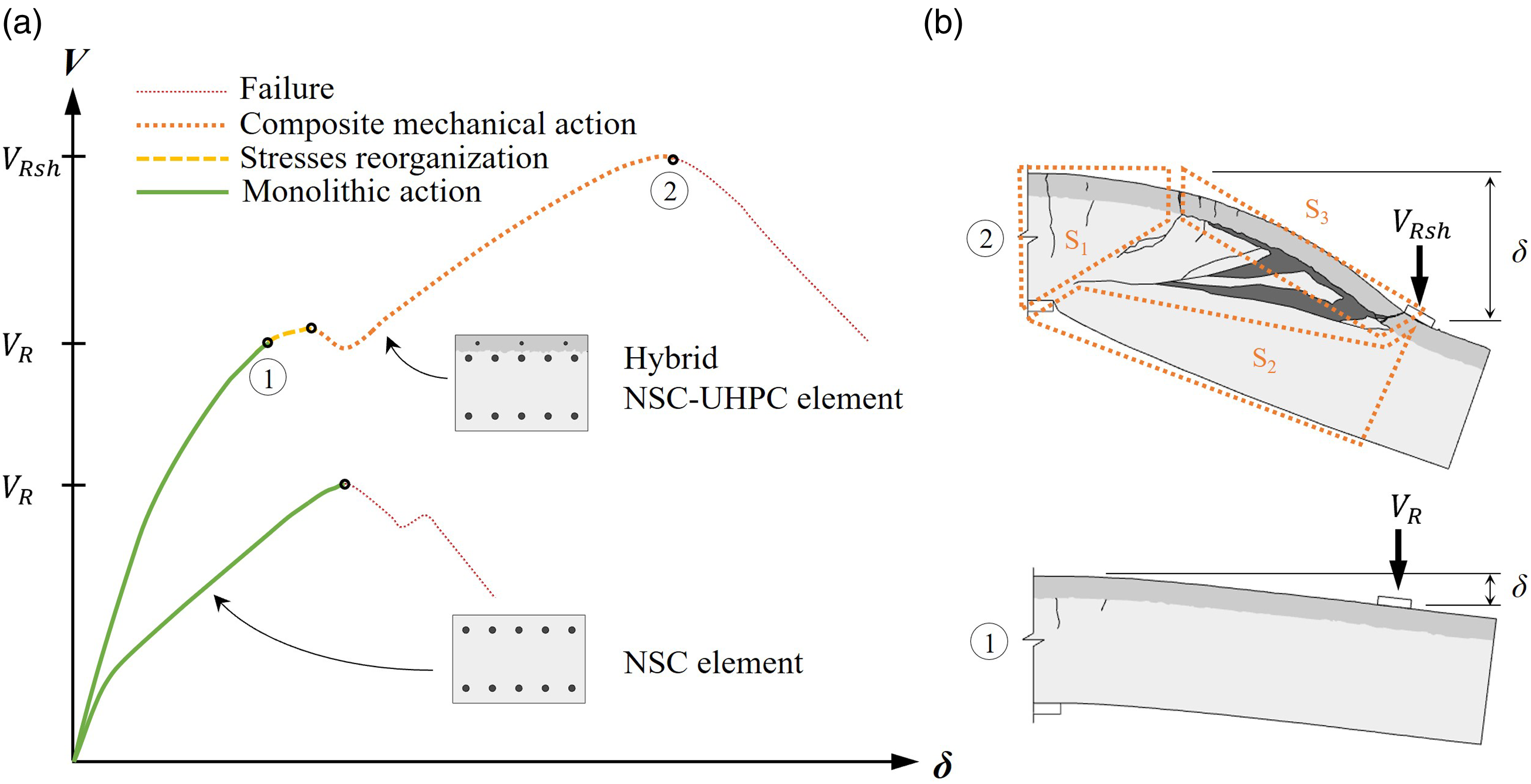
The composite mechanical action develops in four steps (Pharand and Charron, 2022a) (dashed yellow line in Figure 1(a)): (I) diagonal shear crack formation in NSC; (II) UHPC first hinge formation; (III) NSC-UHPC interface delamination and strut stabilization in NSC; and (IV) UHPC second hinge formation. Setting of the mechanism divides the hybrid element into three subsections along its longitudinal axe (Pharand and Charron, 2022a) (➁ in Figure 1(b)). The hybrid trapezoidal subsection S1 sustains bending stresses. The NSC trapezoidal subsection S2 has mainly compression stresses by transferring load directly from the application point to the support. The subsection S3 corresponds to the delaminated UHPC layer with a plastic hinge at each of its extremities (later called nodes). It transfers tensile stresses and a portion of shear stresses.
The main failure criteria observed for the composite mechanical action is concrete crushing of subsection S2 at the tip of the diagonal shear crack (Ji and Liu, 2020; Noshiravani and Brühwiler, 2013; Pharand and Charron, 2022a; Sine et al., 2022; Yin et al., 2017) (Figure 1(b)). Nonetheless, complete UHPC delamination beyond the loading plate (Figure 1(b)) and UHPC tensile failure prior to concrete crushing were also observed (Pharand and Charron, 2022a; Houdoin, 2022).
Presently, SIA (2016) design code is the only standard providing a resistance model specific to the second stage mechanism. The general concept of the Swiss code is to sum NSC, UHPC and stirrups’ individual contribution to the shear resistance. Although the model acknowledges the composite mechanical action in its definition, it does not account for size effect (Sine et al., 2022). Moreover, it does not allow determination of the improved resistance at the end of the first stage, prior the setting of the composite mechanical action.
Therefore, the objective of this paper is to propose new models to evaluate the shear capacity of the monolithic action (
Proposed analytical resistance models
Considering the behaviour of hybrid NSC-UHPC elements under high shear load involves the succession of two bearing mechanisms, two resistance models are proposed. First, the shear resistance model is used to evaluate the resistance given by the monolithic action of the hybrid NSC-UHPC element, V R . Then, based on the computed resistance of the monolithic action V R , the structural hardening model is used to evaluate the resistance given by the composite mechanical action, V Rsh .
For sake of clarity, partial safety factors were not integrated in equations detailed in next sections since it should be adjusted following the jurisdiction considered.
Shear resistance model for V R
The proposed shear resistance model for hybrid NSC-UHPC elements is an adaptation of the Canadian general method for NSC elements shear resistance. Thus, Canadian general method for NSC elements section details the Canadian general method for NSC elements and Modified Canadian general method for NSC-UHPC elements section describes the modifications to the Canadian general method considering the UHPC contribution to the shear resistance.
Canadian general method for NSC elements
In the CSA standard, the general method (CSA, 2014) for the shear resistance of NSC elements V
R
is a simplified model based on the modified compression field theory (MCFT) (Bentz and Collins, 2006). The shear load is assumed to be carried by aggregates interlock within the diagonal shear crack V
c
and by yielding of stirrups that cross the diagonal shear crack V
s
. The shear resistance is thus given by equation (1) where

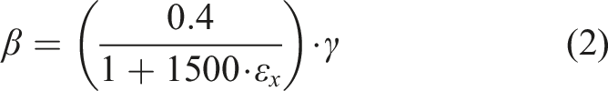
The concept of the Canadian general method is that aggregates interlock factor
In the Canadian general method, compression rebars are assumed to be of equal area than tension rebars and the ratio of


Modified Canadian general method for NSC-UHPC elements
In a hybrid NSC-UHPC element, the UHPC layer acts as an additional rebar layer in terms of ultimate bending resistance (Denarié et al., 2003), but also enhance its behaviour in terms of initial stiffness and crack development (Paschalis et al., 2018; Safdar et al., 2016; Habel, 2004; Oesterlee, 2010; Pharand and Charron, 2022a). This improved mechanical behaviour provides smaller crack width and greater aggregate interlock that must be accounted for the shear resistance of the monolithic action.
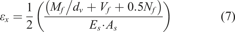
As suggested by the Canadian general method (CSA, 2014), strain of the tensile cord can be estimated by independent contributions of applied loads ( Estimated strain at tensile cord for applied bending moment, shear load and normal load.
For a hybrid NSC-UHPC element, the tensile cord is located at the equivalent static height d
eq
and is computed from the centroid
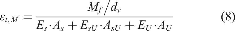

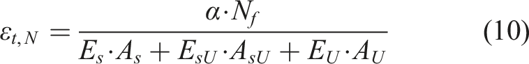
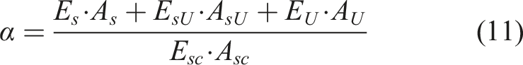

Considering the tensile strain hardening behaviour of UHPC, elastic
Compared to rebars layers (terms
The shear resistance V
R
of the monolithic action of a hybrid NSC-UHPC element is thus computed using equations (1) to equation (6) by replacing the static height of the centroid of longitudinal tension rebars d
s
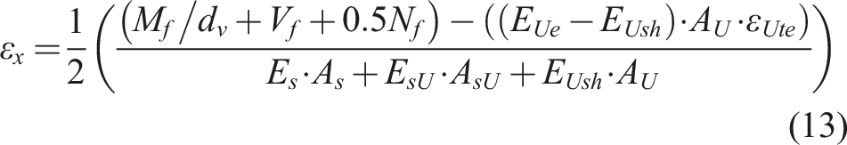
with the equivalent static height from equation (12) and by computing the longitudinal strain at mid-depth
Structural hardening resistance model for V Rsh
The occurrence of a diagonal shear crack within the NSC region of a hybrid element initiates a composite mechanical action which divides the element into three subsections and provides a structural hardening capability to the element, as described in Introduction section. Stresses reorganization acting in that stage takes the shape of a strut-and-tie system with plastic hinges depicted in Figure 3. Figure 3(a) and (b) present respectively principal maximum strain ε
1
and principal minimum strain ε
2
measured from digital image correlation (DIC) in Pharand and Charron (2022a) experimental program. DIC snapshot of slab UD-S were taken at V = 220 kN just before failure, which corresponds to the state ➁ in Figure 1. Strains displayed range from 0 µε in purple to 2000 µε in red for the principal maximum strain ε
1
, and from −2000 µε in purple to 0 µε in red for the principal minimum strain ε
2
. Those ranges were used as the 2000 µε limits corresponds to the yielding strain of Canadian reinforcement and to the assumed plastic strain of a strut-and-tie NSC node (CSA, 2014). Figure 3(c) presents the simplified proposed strut-and-tie model for the structural hardening resistance of a hybrid element. Composite mechanical action mechanism for hybrid NSC-UHPC elements, (a) principal maximum strains, (b) principal minimum strains, (c) proposed structural hardening resistance model.
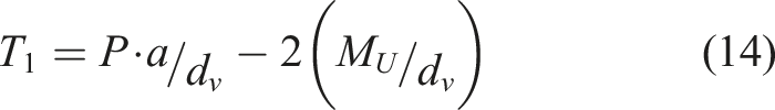
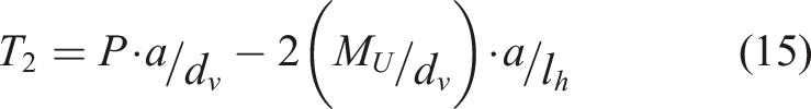
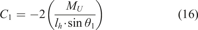
In the simplified proposed model for the structural hardening resistance (Figure 3(c)), ties T 1 and T 2 carry tensile stresses from the applied load P, reduced by the plastic hinges H 1 and H 2 reactions. Both ties’ strength is defined from the combined properties of the tensile cord: NSC rebars, UHPC rebars as well as UHPC layer. Plastic moment M U of hinges is defined only using UHPC layer section properties, which includes the UHPC and its rebars. Strut C 1 at angle θ 1 carries compression stresses from plastic hinge H 1 reaction, while strut C 2 at angle θ 2 carries compression stresses from the applied load P, reduced by the plastic hinge H 2 reaction. Both struts’ strength is defined from the NSC properties. All node locations, except for hinge H 1 , are geometrically determined. Although low orientation angle (<25°) for struts is not recommended (Muttoni et al., 1996), strut C 2 (Figure 3(c)) was defined as such based on experimental data (Figure 3(b)) confirming the formation of a direct strut between loading and bearing plates. Stability of strut C 2 at plastic hinge H 2 is achieved by the fact that the plastic hinge node H 2 is a hybrid NSC-UHPC node crossed by a UHPC tie. Indeed, the UHPC tie significantly reduces the principal maximum strain ε 1 induced at the plastic hinge node H 2 (Figure 3(a)), which does not significantly reduce the effective compressive strength of the NSC within the node.
Forces and angles of inclination of the struts and ties system are given by equation (14) to equation (19) where


Based on the proposed model (Figure 3), four conditions can limit the structural hardening capacity of the composite mechanical action: (I) tensile strength of tie T 1 is exceeded; (II) rotation capacity of hinges H 1 or H 2 is exceeded; (III) NSC-UHPC interface strength at hinge node H 2 is exceeded; or (IV) node-to-strut interface strength of node N c is exceeded. First two conditions are ductile failure type, while last two conditions are fragile failure type.
In this paper, the failure from concrete crushing at the node-to-strut interface of node N
c
is assessed since it is the most frequent failure mode observed for elements with good NSC-UHPC interface and with good UHPC placement (Ji and Liu, 2020; Noshiravani and Brühwiler, 2013; Pharand and Charron, 2022a; Sine et al., 2022; Yin et al., 2017). Figure 4 presents longitudinal strain ε
x
measured from DIC in Pharand and Charron (2022a) experimental program as well as the compression node N
c
from Figure 3(c). In Figure 4(a), DIC snapshot was taken on specimen UD-S at V = 220 kN just before failure, which corresponds to the state ➁ in Figure 1. Strains displayed range from −3000 µε in purple to 3000 µε in red to show NSC compression fracture and UHPC tensile failure respectively. Thick dark lines qualitatively indicate cracks with larger opening. Reduced strut area, (a) experimental DIC results from Pharand and Charron (2022a) experiment, (b) illustration of the fictitious node.
Struts C
1
and C
2
(Figure 3) are combined into a single strut C (Figure 4(b)) by addition of their X and Y components, which eliminates the unknown variable l
h
of the calculation process. The combined strut force C
c
and angle of inclination


Hence, assuming the failure is controlled by concrete crushing at the node-to-strut interface of node N
c
, the structural hardening resistance V
Rsh
of the composite mechanical action is obtained with equation (26) by finding the load P for which the resistance of the node-to-strut interface

Given that plastic moment of the UHPC layer is relatively small compared to the equivalent bending moment corresponding to the structural hardening resistance of the element,
Quadratic equation equation (27) can be rearranged as in equation (28) where A, B and C are quadratic coefficients defined by equation (29) to equation (31). Based on the context of the problem, the positive root (equation (32)) provides the load P corresponding to the structural hardening resistance


In the structural hardening model (Figure 3(c)), eventual stirrups located inside NSC do not directly contribute to the load-bearing capacity of the node-to-strut interface, but rather limit the incursion of the diagonal shear crack into the node N
c
, which results in a larger fictitious node
Experimental data
The proposed models to evaluate the shear resistance V
R
and the structural hardening resistance
A total of 31 hybrid NSC-UHPC elements that showed shear failure were retrieved from five international experimental campaigns. A schematic view of an equivalent cantilever test setup and elements’ cross-section configuration is presented in Figure 5. Configuration type (P, S, R/RS) of cross-section refers to the main function of the UHPC layer (Pharand and Charron, 2022a). In type P, the UHPC layer is unreinforced, and its purpose is to protect the NSC from environmental hazards. In type S, the UHPC layer is reinforced with additional rebars to strengthen the NSC element’s resistance. In type R, the UHPC layer is used to rehabilitate the NSC element by replacing the NSC surrounding rebars with UHPC. Type R becomes type RS if new rebars are added in the original concrete cover to replace rebars damaged by corrosion or to increase more significantly the cross-section capacity. Schematic view of equivalent cantilever test setup and section parameters of experimental data used for models validation.
Summary of cross-section and test setup parameters of the five experimental campaigns.
aStirrups (57 mm2) with 250 mm spacing considered.
bstirrups with 400 mm spacing not considered.
cStirrups (100 mm2) with 250 mm spacing considered.
Summary of material properties of the five experimental campaigns.
The models’ validation with such a large variation of testing parameters and materials properties for hybrid elements will provide a good estimate of their accuracy and confidence in their application.
Validation of the proposed models
Comparison of the proposed models and the experimental results.
aSecond crack considered since stirrups bridged first crack.
bUnspecified in references (Yin et al., 2017; Ji and Liu, 2020).
The predicted resistances Comparison of the proposed models' predictions and the experimental results, (a) shear resistance, (b) strain hardening resistance.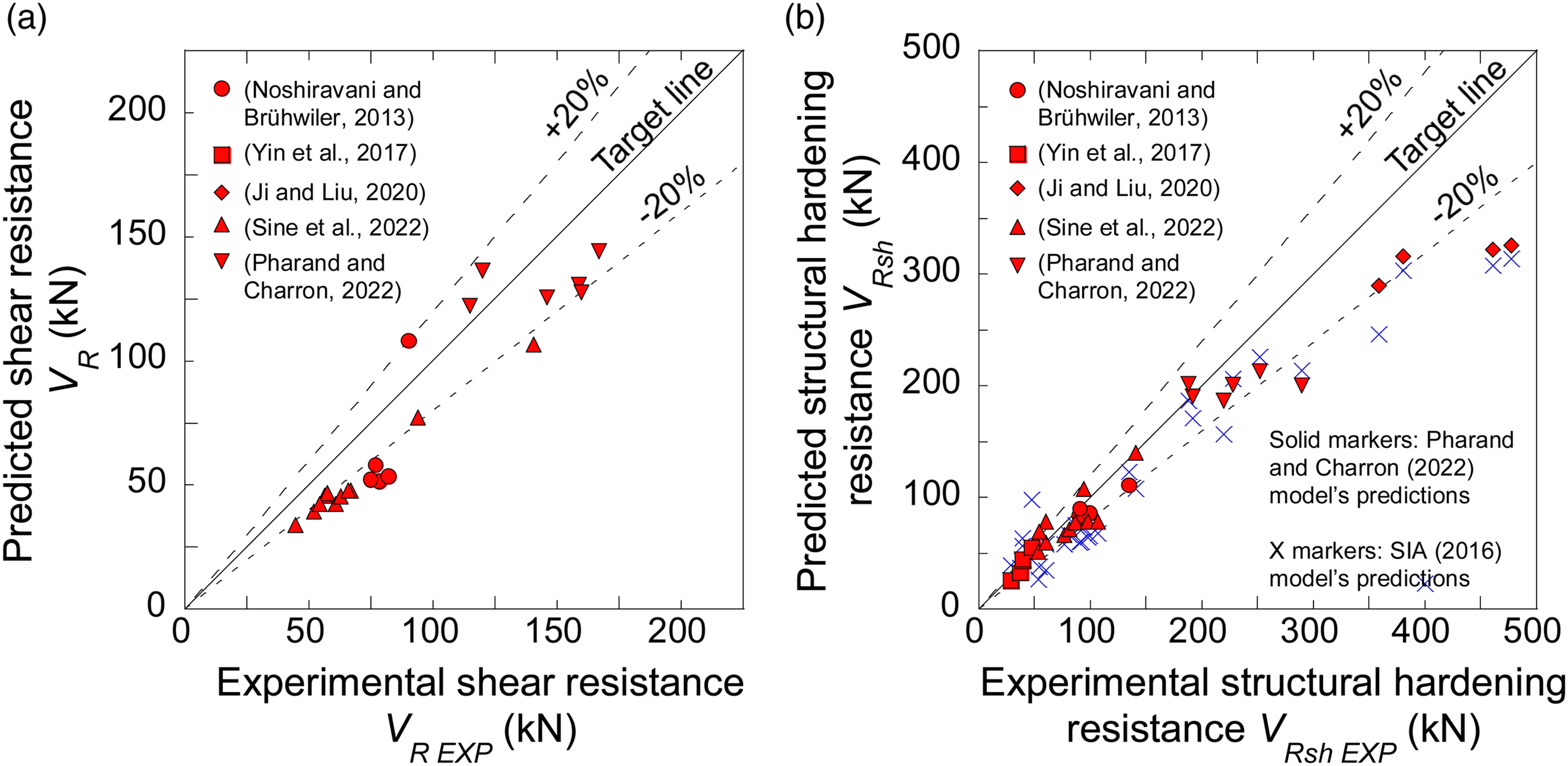
Shear resistance V R
The proposed shear resistance model shows an average resistance prediction ratio (V R /V R EXP ) of 0.81 with a SD of 0.14 (Table 3). This indicates that the proposed model provides generally conservative predictions of the monolithic action’s resistance. Analysis of results could not correlate that specific testing configuration can lead to a particular overestimation or underestimation. There are two explanations to this observation.
First, Yerzhanov et al. (2019) have demonstrated that the Canadian general method is the most accurate model compared to other international design codes model for regular NSC elements. The Canadian general method is yet conservative with a resistance prediction ratio (V
R
/V
R EXP
) of 0.74
1
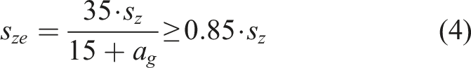
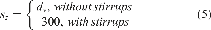
based of a database of 784 beams. Since the proposed model for the shear resistance of hybrid elements integrates UHPC contribution to the general method model for NSC, it shares it conservative accuracy. Furthermore, the Canadian general method uses the effective crack spacing
Second, experimental shear resistance V R EXP , which is defined by the end of the monolithic action of the hybrid cross-section, is measured differently by authors. For Noshiravani and Brühwiler (2013); Sine et al. (2022), V R EXP is defined as the shear load before the sudden small drop in load-displacement curve which marks the end of stresses reorganization in Figure 1. For Pharand and Charron (2022a), V R EXP is defined as the shear load marking the initiation of stresses reorganization. This initiation occurs at a lower load as shown by DIC measurements. As a result, Pharand and Charron (2022a) results are closer to the target line in Figure 6(a), while Noshiravani and Brühwiler (2013) as well as Sine et al. (2022) results are grouped around the −20% line. Overall, reasonable conservative results obtained with the shear resistance model for hybrid elements validate the proposed model which integrates UHPC contribution into the Canadian general method model.
Structural hardening resistance V Rsh
For the proposed structural hardening resistance model, an average resistance prediction ratio (V Rsh /V Rsh EXP ) of 0.93 with a SD of 0.16 are obtained (Table 3), which indicates predictions are accurate, while being slightly conservative. Indeed, for most tested specimens, prediction are grouped around the target tine (Figure 6(b)), except for Ji and Liu (2020) specimens which all predictions are grouped around the −20% line. Specimens from this experimental campaign stand out from others by two factors: these specimens contain stirrups and were tested at the lowest span to equivalent depth ratio (a/d eq ) varying from 2.23 to 2.98 (Table 1). The number of specimens within the five experimental campaigns with a diagonal shear crack intercepting stirrups is very limited. Nonetheless, MN3 falls into this category and its predictions ratio of 0.82 (Table 3) is within one SD of the average, meaning the model’s precision can be adequate with stirrups. Concerning low span to equivalent depth ratio, VB series from Sine et al. (2022) was tested with ratios varying from 2.72 to 2.86 (Table 1) and also had greater dispersion for resistance prediction ratios (0.73–1.30 in Table 3). Hence, the proposed model has a lower accuracy for elements with a/d eq ratio smaller than 2.9.
Performance of the proposed structural hardening resistance model estimating V Rsh can be compared to the one of the SIA design code (2016) for the same 31 hybrid NSC-UHPC elements in Figure 6(b) (blue X markers). In general, the resistance predictions from SIA (2016) model are less accurate than the proposed model: results are more conservative (average prediction ratio V Rsh /V Rsh EXP of 0.88) and show larger scatter (SD of 0.37). SIA (2016) model largely underestimate resistance of Ji and Liu (2020) specimens. Furthermore, its resistance predictions for highly reinforced specimens with a/d eq ratios varying from 5.88 to 7.80 (Yin et al., 2017) are clearly overestimated.
As a result, very good agreement with test results of 31 hybrids beams validate the proposed structural hardening resistance model for the resistance prediction of the composite mechanical action controlled by concrete strut crushing.
Discussion
The original approach of the proposed models performs well for predicting the capacities of hybrid NSC-UHPC elements under high shear load as they integrate the key shear parameters of the two bearing mechanisms.
Bearing mechanisms
Unlike available SIA (2016) design code predicting only the ultimate shear capacity by adding NSC, UHPC and stirrups’ individual contributions, the proposed approach allows prediction of each observed bearing mechanism with distinct models. In the first stage (continuous green line in Figure 1(a)), when the hybrid element behaves monolithically, the proposed model for shear resistance corresponds to a modified version of Canadian general method. The NSC, UHPC and stirrups’ individual contributions are summed up to compute the capacity, which is adequate a monolithic structural element. In the second stage (bold doted orange line in Figure 1(a)), the hybrid element is divided into three subsections (Figure 1(b)) that enables a structural hardening behaviour. The proposed structural hardening model therefore bases the resistance prediction on a realistic strut-and-tie system observed in experimental testing (Pharand and Charron, 2022a). Hence, the proposed approach gives accurate predictions of the shear resistance
Shear parameters
Size effect, reinforcement ratio, span to equivalent depth ratio, compressive strength and magnitude of applied loads are important parameters influencing the shear resistance that must be considered for hybrid NSC-UHPC elements, as it is the case for NSC elements. Since the proposed model for the shear resistance
In the proposed model for the structural hardening resistance
Limitations
The proposed shear resistance model for VR predicts the shear resistance of the monolithic action while the proposed structural hardening model for V Rsh predicts the ultimate resistance of the composite mechanical action controlled by the concrete crushing of the combined strut. Both models were validated for a wide range of repair configurations (P, R, S and RS) on beams and unidirectional slabs (total height (hc + hU) varying between 100-690 mm, ratio of UHPC to NSC heights (hU/hc) varying between 0.15-0.50, ratio of span to equivalent static depth (a/deq) varying between 2.23-7.80) as well as various materials properties. Depending on the construction process, NSC-UHPC interface characteristics as well as fibers orientation and density may lead to other types of failure such as limited hinges rotation capacity, limited ties capacity and limited NSC-UHPC interface capacity. Further experimental and numerical research is needed to evaluate extend of the main and each secondary failure mode. Then, the model could be improved to capture all shear failure modes of hybrid NSC-UHPC elements.
Conclusion
The use of UHPC as repair material for deficient NSC structural elements is growing. However, design codes are not yet fully developed to represent both the monolithic and the composite mechanical actions showed by hybrid NSC-UHPC elements under shear load. This paper addresses the evaluation of the shear resistance V
R
from the monolithic action and of the structural hardening resistance V
Rsh
of the composite mechanical action for hybrid NSC-UHPC elements by proposing two models based on the Canadian design philosophy. The following point can be highlighted: 1. The shear resistance model evaluates the shear load at which the hybrid section ends its monolithic action due to the localization of a diagonal shear crack in the NSC. The model integrates UHPC contribution for the strain at mid-height estimation to the Canadian general method model. 2. The shear resistance model offers reasonably accurate and conservative results with an average predictions over experimental results ratio of 0.81 and with a SD of 0.14. 3. The structural hardening model evaluates the ultimate load the composite mechanical action can sustain. It is modelled using a strut-and-tie system with plastic hinges. Struts are defined by NSC properties, ties are defined by the total tensile cord properties, while plastic hinges are defined only by the UHPC layer and its embedded rebars properties. 4. The concept of the structural hardening model differs from conventional models by evaluating the resistance of a NSC node-to-strut interface rather than by summing NSC, UHPC and stirrups individual shear resistance contributions. 5. The structural hardening resistance model offers accurate and mostly conservative results with an average predictions over experimental results ratio of 0.93 and with a SD of 0.16.
The proposed models are an initial attempt to offer simple and intuitive design tools for the shear resistance of hybrid NSC-UHPC elements. Even though predictions are in very good agreement with experimental data, additional modules should be developed to evaluate capacity of other possible types of failure within the mechanical composite action.
Footnotes
Declaration of conflicting interests
The author(s) declared no potential conflicts of interest with respect to the research, authorship, and/or publication of this article.
Funding
The author(s) disclosed receipt of the following financial support for the research, authorship, and/or publication of this article: This project was financially supported by the Discovery Grant of the Nature Science and Engineering Research Council of Canada (NSERC) granted to Prof. J.-P. Charron; and by a PhD Scholarship of the Fonds de recherche du Québec – Nature et technologies (FRQNT) awarded to M. Pharand.
Credit authors statement
Pharand, M.: Conceptualization, Methodology, Software, Investigation, Formal analysis, Writing – Original draft, Review and Editing, Visualization.
Charron, J.-P.: Conceptualization, Methodology, Formal Analysis, Resources, Funding acquisition, Writing – Review and Editing, Supervision.
Data availability statement
All data and models used during the study appear in the submitted article or are available from cited references.