
Abstract
In this study, the damage effects of a new building heating system that activates the reinforced concrete columns (RC) which are the structural elements of the building by thermal cycles were investigated. The research was carried out experimentally on real-time data. The thermal fatigue effect that will occur after the structural RC is exposed to repeated thermal cycles was evaluated with the lateral cyclic loading test. The effect of the applied thermal cycles on the microstructure of the concrete was also tried to be observed. According to the data obtained in this study, in the preferred concrete type and geometry, the mechanical performance of the RC was not adversely affected at preferred operating temperatures and the number of applied thermal cycles. The results obtained are very promising in terms of the applicability of the new system as a preliminary study. In the proposed system, structural elements will be used as heater and energy storage throughout the life of the building. Therefore, it is essential to predict the exact thermal stress and strain values that the RC will be exposed to, and most importantly, the thermal fatigue life of the structural element under different parameters by future work.
Keywords
Introduction
Today, one of the world’s foremost need is energy. Using and storing energy in the most efficient way is a current and interesting research area. A significant part of the energy consumption in the world is the need for heating in the winter or cooling in the summer. Therefore, energy efficient building design has gained importance. Systems that can store energy and use it when necessary have been tried to be integrated into buildings. In the literature, there are numerous studies on energy storage technologies for buildings (Navarro et al., 2016; Navarro et al., 2016; Rathore and Shukla, 2019; Rathore et al., 2022; Romdhane et al., 2020).
Starting from energy efficient building design, the idea of energy storage in reinforced concrete columns (RC), which are the structural components of buildings, and heating the building with RC, was proposed (Unalan and Ozrahat, 2014; Ozrahat and Unalan, 2017). Among the materials used for building technology the concrete is an important construction element in terms of large mass or volume the concrete columns constitute nearly half of the material used in a building construction. This large mass serving higher energy storage will be an important advantage in thermal energy storage.
The working principle of the proposed system is as follows: The sensible thermal energy from the energy center would initially be stored by means of forced convection in column medium. Then, while a part of the stored thermal energy will transfer by natural convection and radiation from the column surface to indoor spaces, the rest of the thermal energy in column will conduct to building elements such as wall, beam, ceiling and floor connected to the column. Thus, heat transferring surface will considerably increase compared to conventional heating systems. A man in the room will expose to the radiation heat flowing in many directions. This will an important advantage in terms of thermal comfort. There will not appear strong local air circulations that are caused by forced convection in fan coils or by a strong convection nearby the radiator which has higher surface temperature. Generally, the traditional systems causes greater temperature fluctuations in the room. The new system could be a heating system that works in an almost steady state regime. Therefore, the temperature distribution as a function of the time and space will be more uniform (Unalan and Ozrahat, 2014).
The proposed energy storage and heating system is based on the heating and cooling of RC by repetitive thermal cycles. In addition to the load-bearing task, the structural element is also assigned the task of heating and energy storage. The thermal results obtained from the system, the thermal performance of which has been investigated in detail, show that reasonable and sufficient heating can be achieved at the temperature values below 100°C in the RC structure. However, throughout the life of the building, the RC will be exposed to periodic thermal cycles. In this case, thermal fatigue is expected in the RC. Thermal fatigue is very important for the applicability of the system and needs to be investigated in detail.
In the literature, daily and annual environmental temperature changes are also considered as thermal cycles. Severe climatic conditions were analyzed as a fatigue process. In one of the studies carried out for various concrete and reinforced concrete structures exposed to harsh climatic conditions; the effect of environmental thermal fatigue (ETF) on concrete performance based on mesostructural and microstructural analyses was investigated and an ETF test method was proposed (Huang et al., 2019).
The fatigue behavior of concrete in cyclic low-temperature impacts was investigated and an experimental-analytical generalization of the measurement of the following indicators: strength, components of deformations, cracking, and the energy potential of concrete destruction during the exhaustion of its frost resistance were presented (Pinus and Каlаshnikov, 2019).
The thermal fatigue cracks occur in regions with moderate climates as a result of cyclic thermal strains/stresses within the restrained pavement layers. An experimental setup is developed to measure thermal fatigue resistance of asphalt concrete specimens under constant strain amplitude loading (Arabzadeh and Güler, 2019).
A concrete fatigue test program after a temperature cycle of 50°C–70°C to study the effect of pore structure changes on the fatigue life of concrete in areas with large temperature differences was designed. Some important parameters which provide basis for the prediction of the fatigue life of concrete on the basis of pore structure were proposed (Shi and Zhao, 2021).
The flexural fatigue behaviour of an ultra high-performance fibre-reinforced concrete and its corresponding matrix without any reinforcement in terms of its S-N curves at different temperatures (room temperature, 100°C, 200°C and 300°C) were reported (Ríos and Cifuentes, 2018).
Both the traffic and temperature effect on the fatigue safety of a reinforced-concrete bridge deck based on monitoring data were investigated and an integral approach to identify fatigue damage of a reinforced-concrete deck as a function of the relevant actions for fatigue using monitoring data was presented (Bayane et al., 2019).
The fatigue behaviour of rock asphalt concrete considering moisture, high-temperature, and stress level was investigated and fatigue equations considering moisture and stress level to predict the fatigue life of rock asphalt concrete at different temperatures were established (Ren et al., 2021)
In the above studies, thermal fatigue studies were carried out for concrete and reinforced concrete structures with different properties and used for different purposes. Models that will contribute to the literature have been developed. However, there is still no study in the literature on the mechanical behavior when repeated thermal loads are applied to the structural elements of the building that are currently bearing loads. The subject of mechanical fatigue is not a new topic for the literature. Thermal fatigue is similar to mechanical fatigue, but the stresses are developed by temperature gradients. Thermal fatigue occurs at locations where the thermal gradient is greatest. In this new heating system, the most important modification is the placement of steel pipes at the centre of the columns during the manufacturing phase. These pipes serve as fluid flow channels. With hot fluid flowing through the pipes, it is intended that the heat can be stored in the column. Thus the heating or cooling of the interior environment of the building will be provided. Therefore, a thermal gradient will form within the RC. For this reason, an extra thermal stress will be loaded on the column due to a decreasing temperature gradient from the concrete pipe interface to the outer surface of the column. It will also be subject to thermal fatigue due to repeated thermal stress. The proposed heating system is expected to overcome these two major problems. This study can be considered as an initial study on the thermal stress and thermal fatigue problem that needs to be addressed.
The aim of this study is to see the effect of repeated thermal cycles on the structural performance of the RC over a certain period of time. Since the RC is manufactured in real dimensions and exposed to thermal cycles experimentally, lateral cyclic loading test is thought to be appropriate for structural performance. Further detailed studies will continue with the promising results obtained. In particular, a significant contribution will be made regarding the thermal fatigue behavior of the RC column with a steel pipe under periodic thermal loading at temperatures lower than 100°C.
Experimental study
Test columns
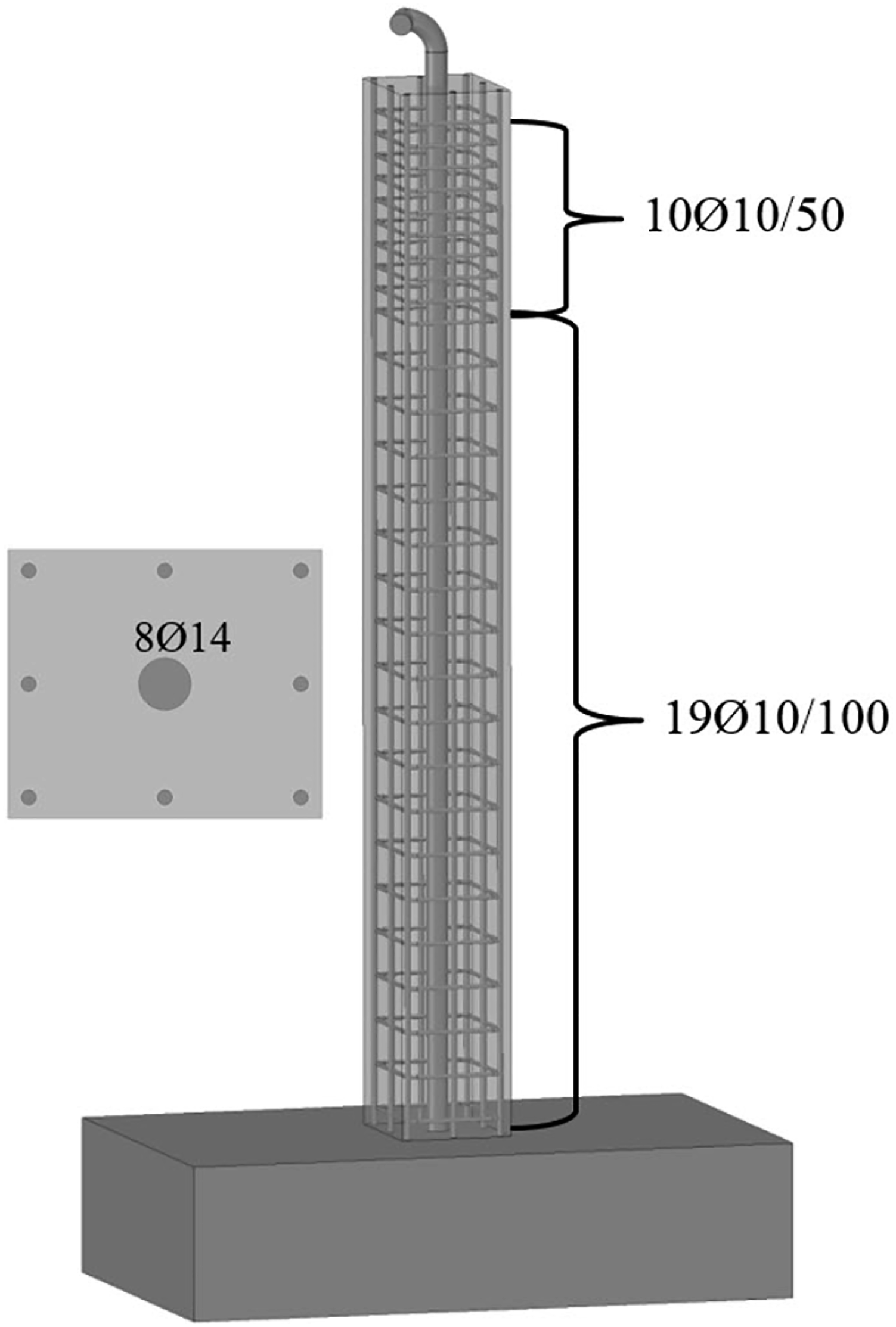
For the experimental studies within the scope of this study, three RCs constructed of the same materials and same dimensions were evaluated (Table 1). Two of these columns are RC columns with steel pipes placed on the neutral axis of the column during the construction process. These placed steel pipes serve as airflow tube. One of these two columns is thermally fatigued by being subjected to repetitive heating-cooling or charge-discharge cycles. In the following sections, this column is defined as Thermally Fatigued Reinforced Concrete (TFRC) column. In the other piped column, no heat treatment was performed and this column is defined as Thermally Unfatigued Reinforced Concrete (TURC) column. In addition to this, a gapless column produced by other researchers and evaluated in another study (Yağmur, 2012) was considered as a control column and defined as Gapless Reinforced Concrete (GRC) column in the following sections of this study. This gapless column and the other two columns in this study were produced simultaneously using the same materials. By comparing the mechanical behavior of GRC, TFRC and TURC columns, not only the effect of limited thermal cycling but also the effect of steel pipe (inner and outer diameters are 52.48 mm and 60.3 mm) placed on neutral axis was examined. The cross-section dimensions of the column is 300 × 300 mm. The height of the columns is 2360 mm and is produced with the foundation of 2000 × 1500 × 600 mm. The constructed RC columns are shown in Figure 1. The reinforcement details of RC columns are given in Figure 2. It can be understood from the figures that the steel pipe (or can be named as airflow tube) is placed in the core of the RC columns at construction process. Constructed test columns. Reinforcement details of the test columns. Cross-section details and definitions of the test columns.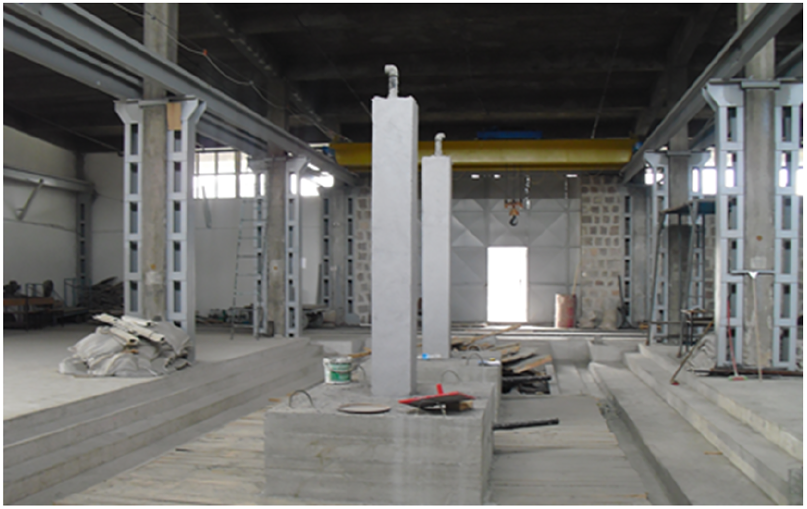

All tested columns were produced with same concrete having a compressive strength of 40.46 MPa. Mechanical strength of the concrete was determined with six cylindrical specimens of 10 × 10 cm seen in Figure 3. Cylindrical concrete samples for compressive strength tests.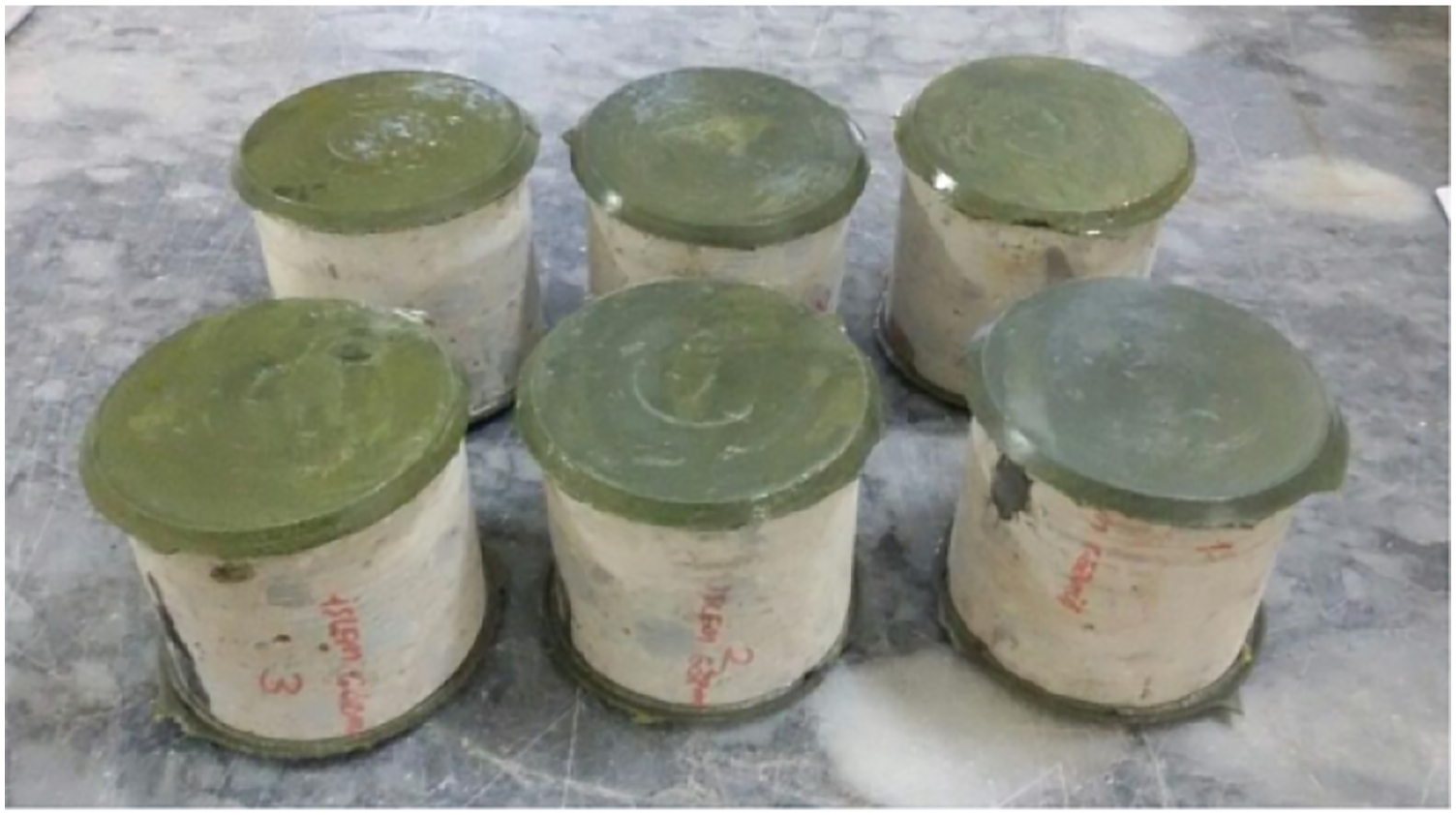
Thermal cycling experiments
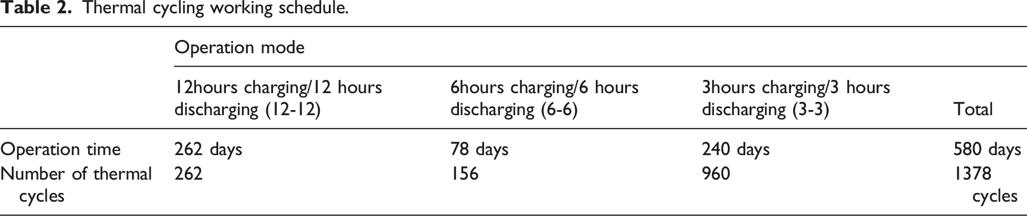
Building heating systems are used during the winter season and remain idle in the summer season. In the system seen in Figures 1 and 2, thermal comfort can be provided inside the building by flowing hot fluid in winter and cold fluid in summer. In this study, tests were conducted only for winter season. The heating system operates in different regimes during the day. Thermostat system can be activated continuously with shorttime work/stop regime, but can also be activated at certain time periods of the day. In general, heating systems in buildings in Turkey are operated twice in a day for 3–5 hours in the morning and evening. In this study, it is assumed that the heating (thermal energy charging) periods in the column heating system are performed in certain time periods of the day. Except for the heating period, the energy loaded on the columns will flow to the internal environment (thermal energy discharging). In the scope of this study, years of heating-cooling exposure experiments or thermal cycling experiments simulating charging-discharging cycles were applied to TFRC column for a total of 580 days in 3 years. A closed circuit, which is connected to the test specimens shown in Figures 1 and 2, is formed by connecting a store-fan-heater system between the pipe outlet and the foundation entry on the column. The air heated in the store was sent to the test system from the foundation entry with the help of a fan. Air coming out of the columns has returned to the store. Air with ambient temperature at the beginning of the experiment was increased over time. In order to prevent sudden temperature changes, the fan was operated continuously until the air temperature in the store was down to 50°C. Experiments were carried out with different charging-discharging periods. Selected periods are 12-12, 6-6 and 33. In 12-12 experiments, hot air was passed through the pipe in the column for 12 hours and the air heater system was turned off for the remaining 12 hours. This process was repeated for a specific number of days in a row. In 6-6 experiment, 6 hours charge followed by 6 hours discharge. This process was repeated 2 times a day. In the 3-3 experiment, the 3 hour charge and 3 hour discharge process was repeated 4 times in a day. For all working regimes, measured air temperature versus time at the base entry of the test system is shown in Figure 4 for the 96 hour-slice. The inlet temperature of the hot air is 162°C and this is the maximum temperature allowed by the heating system. Airflow temperature versus operation time for different thermal cycling experiments.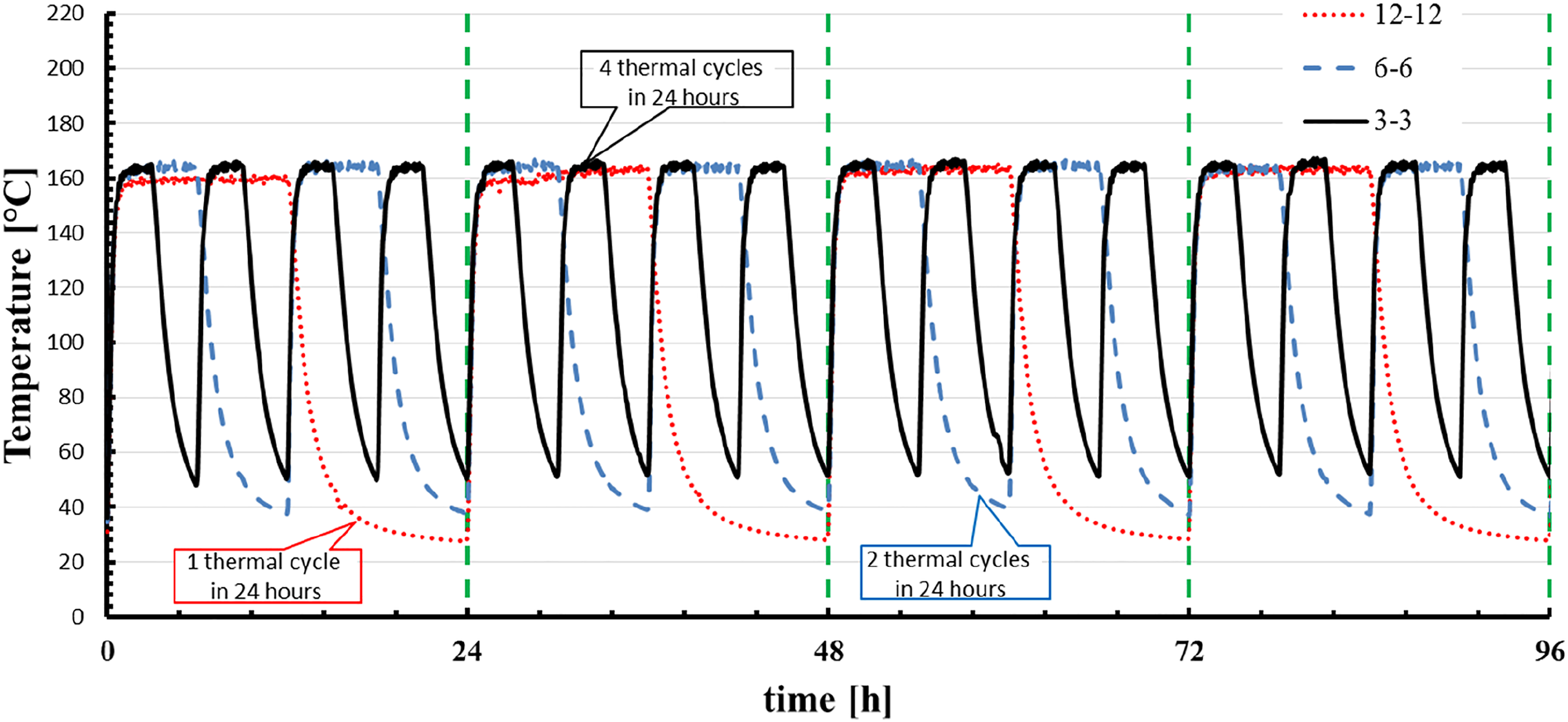
Thermal cycling working schedule.
Temperature gradient inside the TFRC column
Temperature measurements were taken from pipe inlets (inlet air temperature), pipe outlets (outlet air temperature) and column surfaces in the thermal experiments. However, it is obvious that the maximum temperature value in the RC column exposed to thermal cycling occurs at the steel pipe-concrete interface. Temperature measurement from these points was not performed to avoid damaging the column cross-section. The highest stress in the mechanical tests of the column is expected to be at the foundation-column junction. Therefore, it is important to determine the temperature at the steel pipe-concrete interface (point T1 in Figure 5) in the plane of column-foundation connection. This non-measured temperature was calculated numerically. It was calculated according to the numerical calculation process and conditions as given in Ref.7. The numerical calculation process that used in Ref. 7 provides at least 95% correlation (maximum 5% error) with experimental results and it was conducted with ANSYS FLUENT Version 15 (ANSYS, 2015). In the calculations, air temperature and flow rate were selected as 162°C and 8.4 m/s. In addition to point T1, the temperature of point T2 was calculated to determine the temperature at the concrete and pipe interface at the column outlet. Details of points T1 and T2 can be seen in Figure 5. Location details of T1 and T2 points.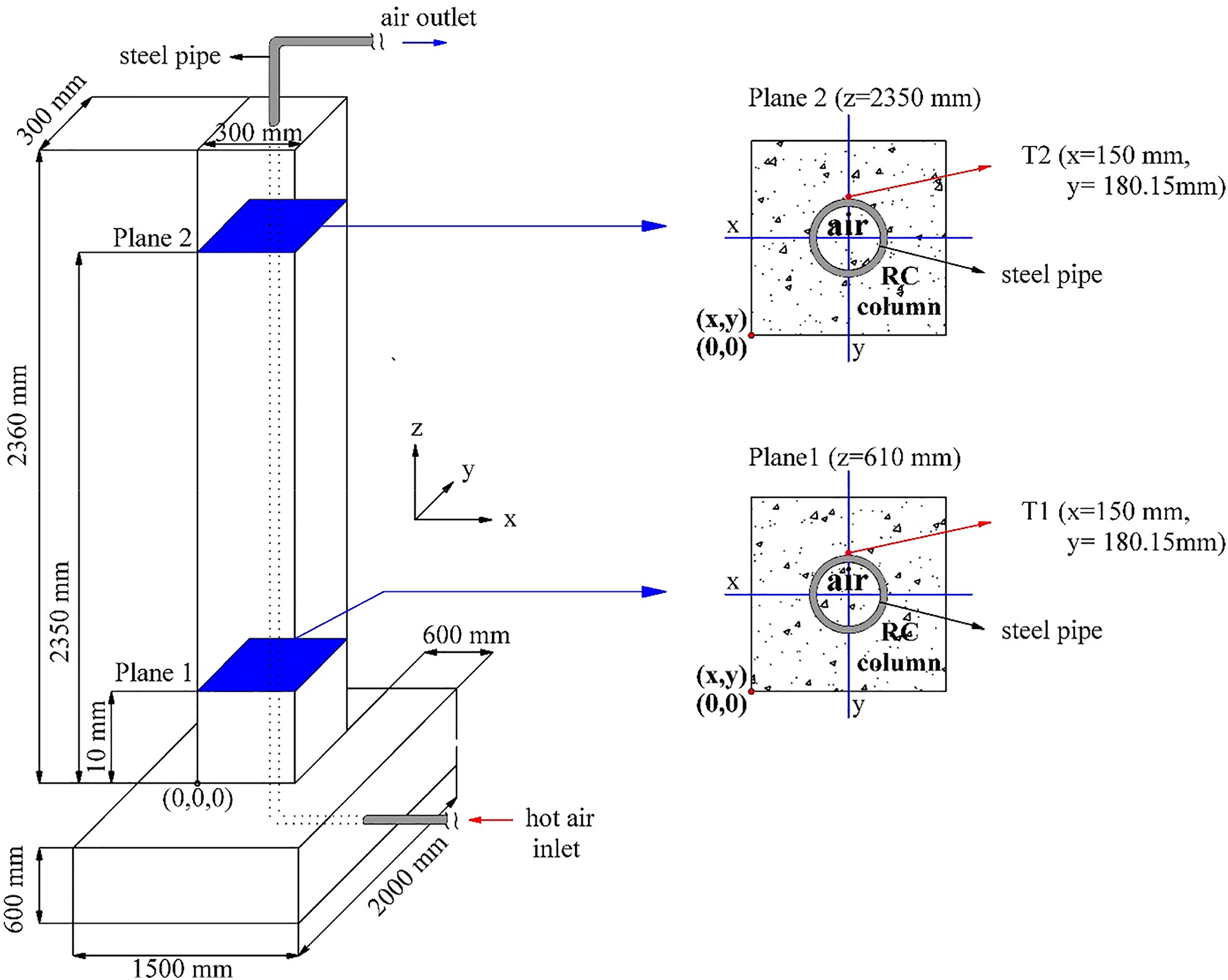
The variation of temperature values over time of T1 and T2 points are presented in Figure 6 for the first 156 hours. According to Figure 5, T1 and T2 values reach their maximum values after 36 hours. These values were calculated as 86°C (359 K) and 64°C (337 K) for T1 and T2, respectively. According to these results, the column is exposed to temperature changes and therefore it is also exposed to thermal fatigue both in the axial direction (flow direction) and in the radial direction (direction perpendicular to the flow). While the air flow temperature is 162°C, Point T1 is 86°C. Point T1 is heated and cooled between 86°C and 55°C during the thermal cycle. Column surface temperatures vary between 40–45°C depending on time (Ozrahat and Unalan, 2017). Thus, the temperature difference between the concrete-pipe interface and surface of the column with a cross-section of 300 mm × 300 mm varies between approximately 45°C and 10°C. This temperature gradient plays an effective role on the fatigue performance of the RC column. According to the experimental results, with an air temperature of 162°C and a flow rate of 8.4 m/s, an average heat flow of 400 W can be achieved from the experimental column surface. This value of the heat flux was found to be sufficient for the thermal comfort of the interior areas of the building (Unalan &Ozrahat, 2014; Ozrahat and Unalan, 2017). Temperature values versus time at point T1 and T2 during the accelerated thermal cycling.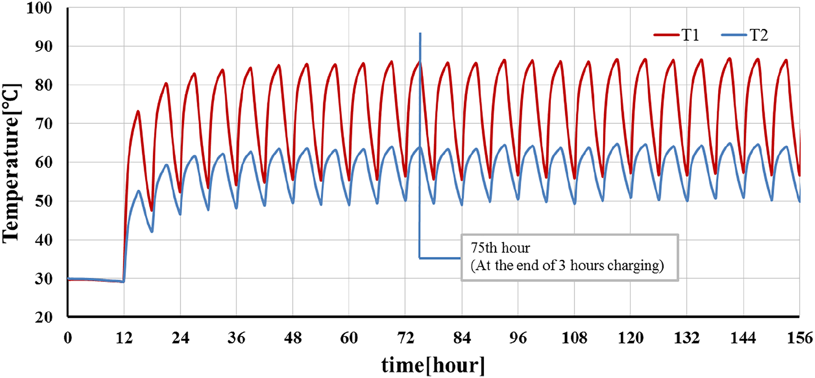
Figure 7 shows the temperature gradients that occur in the whole system at the end of the charge period in the 11th cycle (75th hour). As can be seen, the temperature values change in all three directions. Thus, the column was exposed to thermal stresses and thermal fatigue in all three directions. Temperature contours of reinforced concrete columns test column at 75th hour.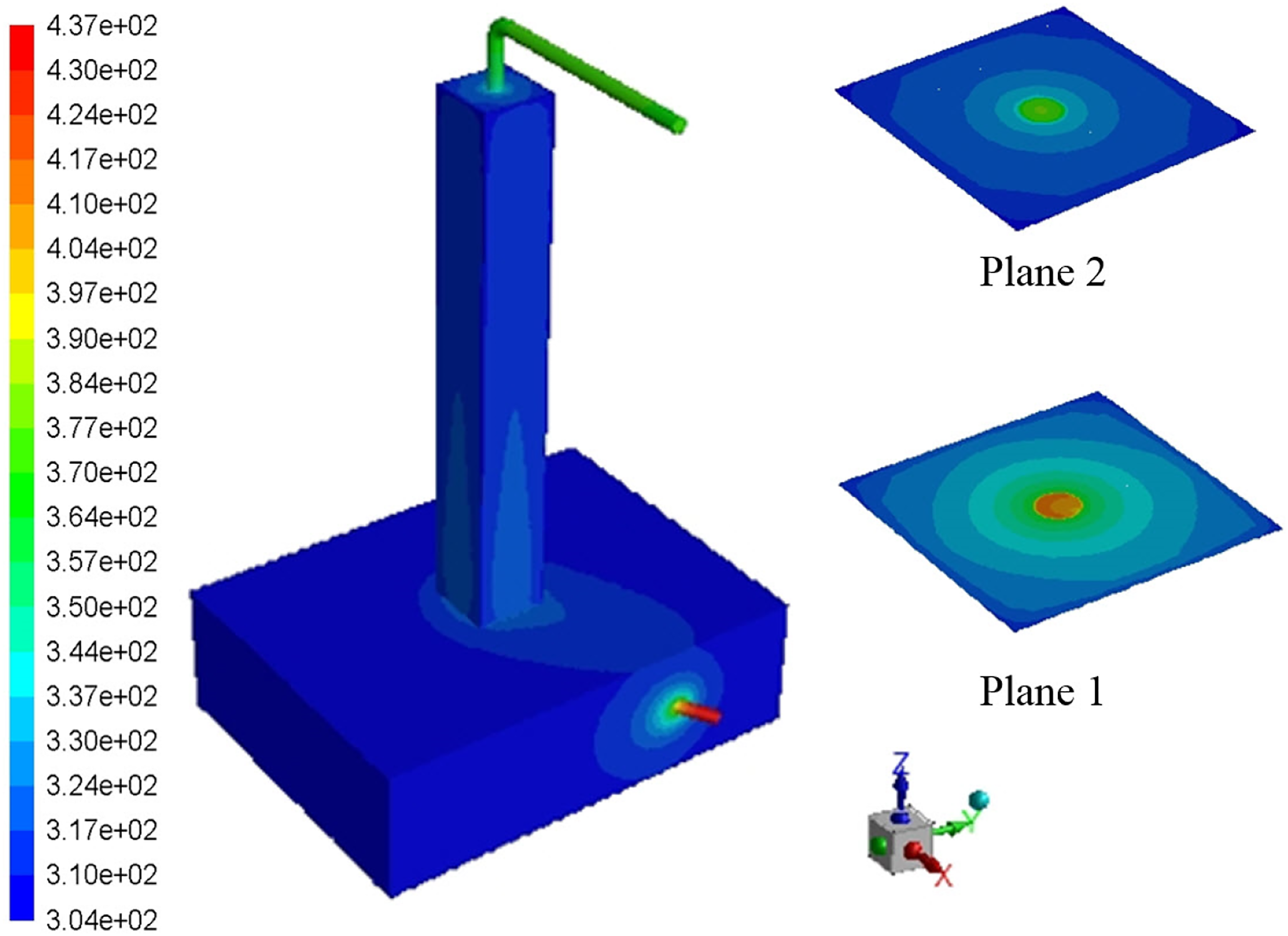
Mechanical experiment
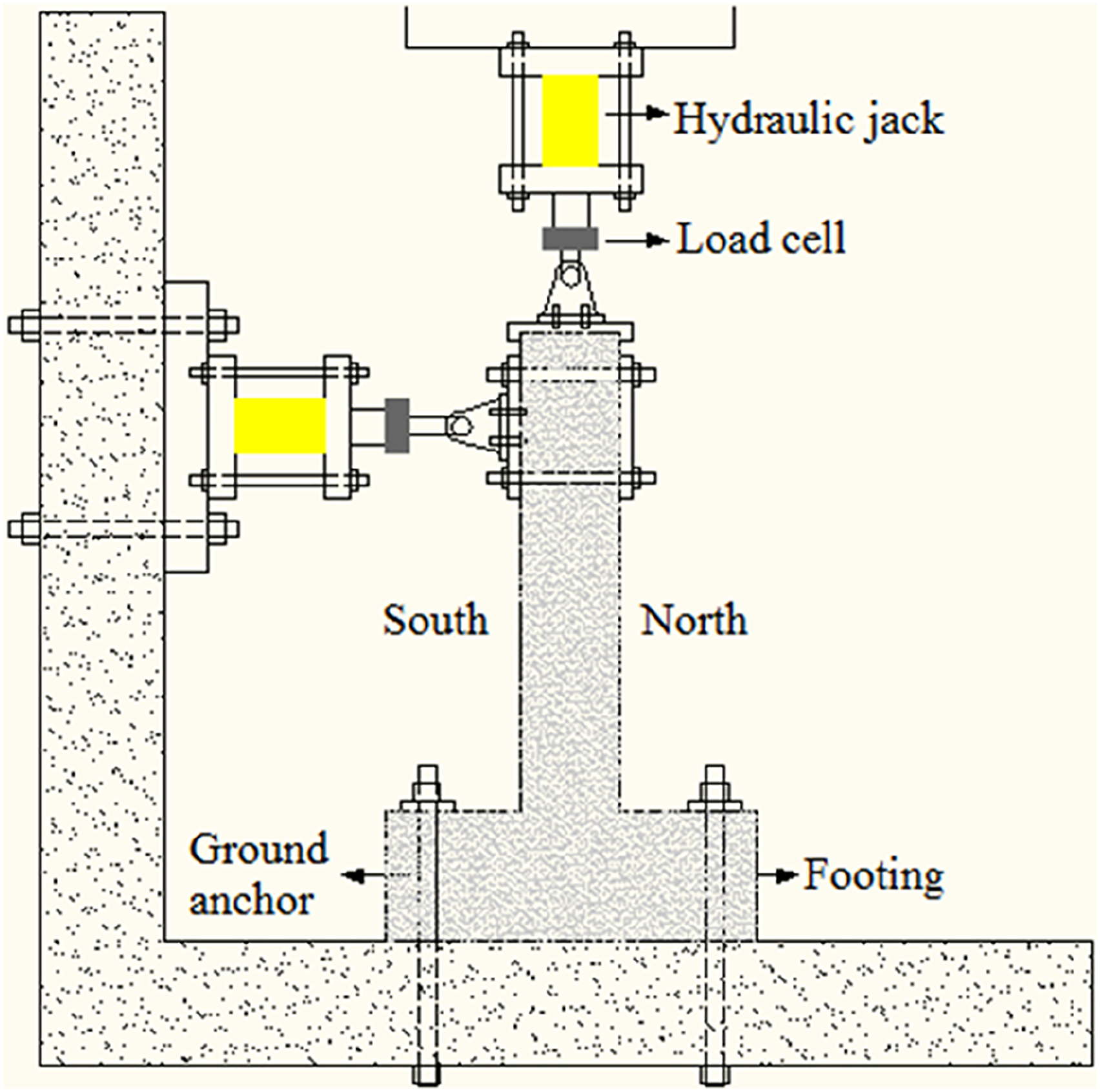
The hysteretic behavior of the columns under cyclic lateral load and the strength envelopes obtained from the hysteresis curves show the earthquake performance of the columns. Because the strength envelopes reveal the capacity of the columns depending on the material quality, dimensions, and cross-section details. Although the earthquake effect is a dynamic load effect, it is not possible for the columns to be loaded more than their capacity during an earthquake. In addition to this, columns are the structural elements of the axial load (AL) effect as well as the lateral shear force and bending moment. In order for this situation, which is defined as the combined bending effect, to be taken into account, the columns must be subjected to an AL of at least 10% of their AL carrying capacity (ACI-318-19, 2019; TS500, 2000; TEC, 2018). Therefore, TFRC and TURC columns were tested under constant AL and cyclic lateral displacement. The experiment set is given in Figure 8. The AL is expressed by the following equation (ACI-318-19, 2019) Experimental setup.
In this equation, Ag refers to the column cross-sectional area and fC refers to the characteristic compressive strength of concrete. Lateral loading protocol is given in Figure 9. Push and pull directions are defined as positive and negative respectively. The initial value of the displacement (a1) was applied as 3.54 mm and the subsequent values were increased according to the equation ai+1 = 1,4ai. The final displacement amount was applied as 92.04 mm. Each displacement cycle was performed twice (FEMA-461, 2007). The cyclic repetitive lateral load was applied up to the level of 80% after peak load (Vmax). Lateral loading protocol.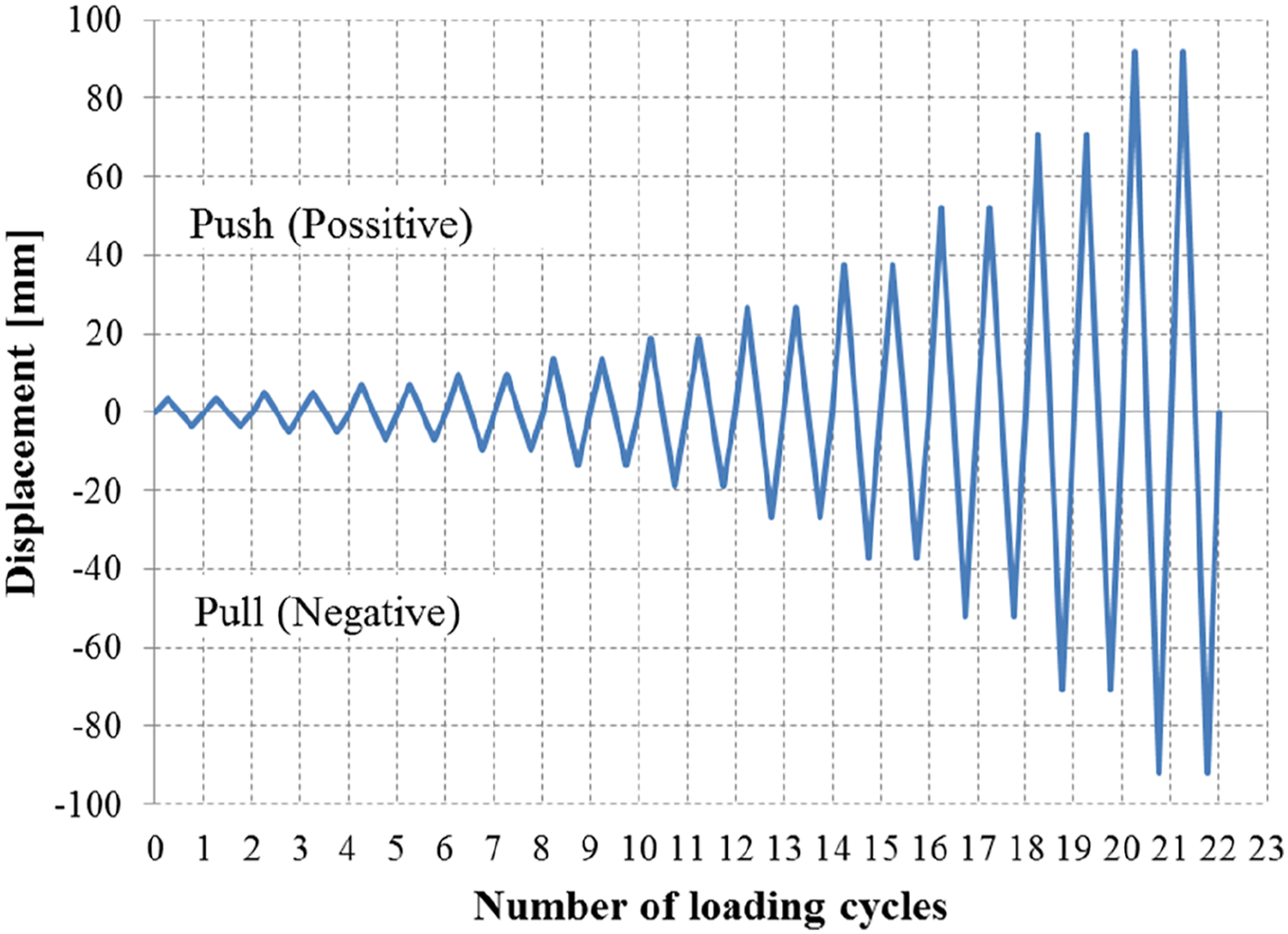
Lateral displacements were measured using linear variable differential transducers (LVDTs). Four 100 mm LVDTs were used to measure lateral displacements. Two of these devices were positioned opposite to each other at the lateral loading level. The other two were located in the middle and lower region of each column. Three LVDTs were fixed with a frame which was fixed to the floor.
Results and discussions
Macro and micro changes in concrete-pipe interface and in concrete structructure
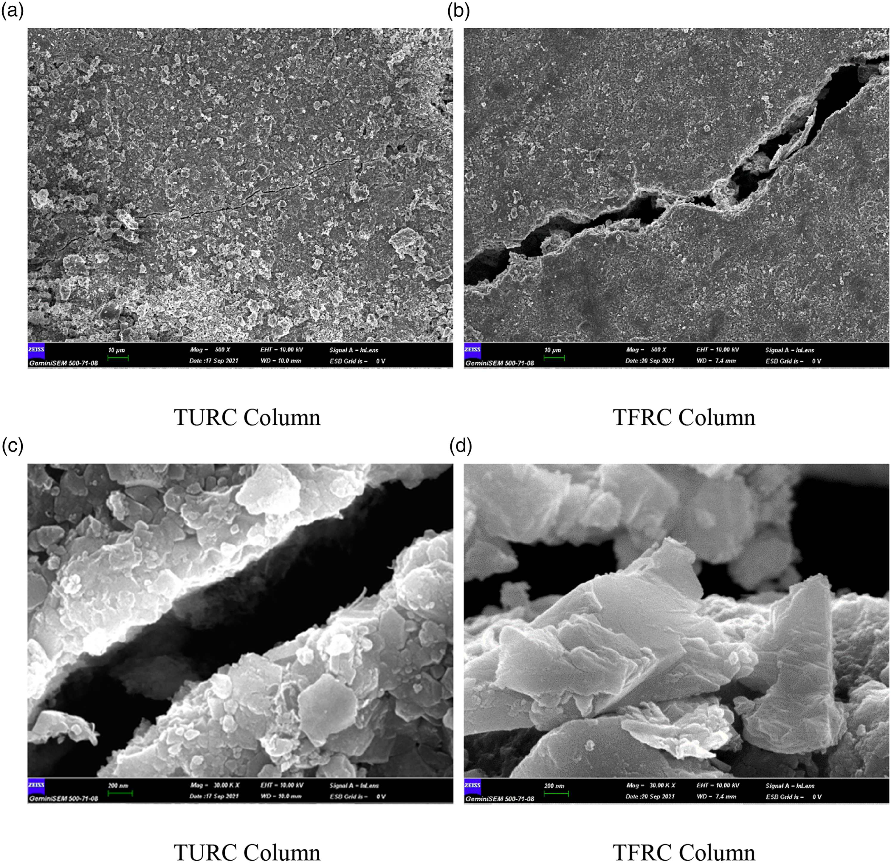
After the thermal cycles, it was desired to observe the changes in the concrete material within the column. For this purpose, samples were taken from TURC and TFRC columns. Sampling took place after both the thermal test and the mechanical test were completed. The samples taken are shown in Figure 10. Looking at the two samples, there is no difference in macro scale. No observation or comment could be made on possible color differences in the concrete due to the black color of the pipe penetrating the interface. However, for a more detailed evaluation, SEM images were taken from the concrete-pipe interface from both column samples. These images are given in Figure 11. In Figure 11(a) and (b), crack formation at the interface is seen. Although it is not possible to observe the cracks in the interior of the column before the mechanical tests, it is thought that the interior surface cracks in the thermally unfatigued TURC column are caused by the interfacial stresses between the concrete and the steel pipe due to the lateral cyclic loading. On the other hand, lateral cyclic loading and thermal cycles are thought to be effective together in the formation of interfacial cracks in the thermally fatigued TFRC column. In Figure 11(c) and (d), the differences in the microstructure between the two columns became evident. The changes within the TFRC column are given in detail in Figure 12. The crystallization that occurs as a result of thermal cycles is clearly seen here. The differences observed in the Figures 11 and 12 between TURC and TFRC column directly related with some important parameters of concrete material such as porosity and compressive strength after repeated thermal cycling. Photographs of the concrete-pipe interface of thermally unfatigued reinforced concrete and thermally fatigued reinforced concrete columns from left to right respectively. Sem images from the concrete-pipe interface. Detailed SEM images from thermally fatigued reinforced concrete.
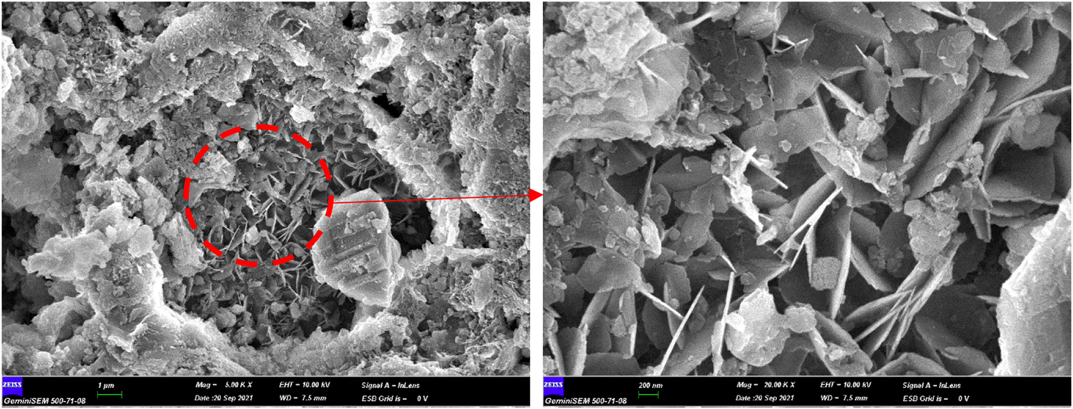
It was indicated in the literature that thermal cycling changed the pore size distribution of the cement matrix. The rehydration reaction refined the pore structure then followed by an increase in total porosity and coarsening of the pore structure (Huang et al., 2019; Zheng et al., 2022). The reason of this result is explained as the most important component of concrete is hardened cement paste, which is mainly composed of crystals, amorphous products, and pores generated by the hydration reaction of cement (Shi and Zhao, 2021). SEM observations after 150 thermal cycles showed the presence of network-like hydration products, such as C-S-H gel, needle-like and granular crystals, such as ettringite, within the pores. (Huang et al., 2019). The needle-like (Figure 12(a) and (b)) and granular (Figure 11(d)) crystals of TFRC column are the hydration products after the thermal cycling process.
On the other hand, it was concluded in the literature that from room temperature to 300°C, compressive strength of concrete keeps constant or even increases slightly. Between 300–800°C, compressive strength of concrete decreases dramatically. 800°C afterwards, almost all the compressive strength of concrete has been lost (Ma et al., 2015). In some cases, it is observed that the compressive strength increases up to 200°C and subsequently decreases with further increase in peak temperature (Khan and Abbas, 2016). It was indicated that the performance of concrete when exposed to elevated temperature is greatly affected by the concrete type. It was cleared that silica fume or fly ash increase the compressive strength of concrete at 200°C (Alhamad et al., 2022).To address the influencing mechanism of thermal cycling on the mechanical properties and microstructure of cement-based materials some researchs are conducted. An experimental research reported that compressive strength continuously declined as the thermal cycles (between 5°C–45°C) lengthen. The compressive strength of O-4, O-5, and O-6 (w/c) ratios decreased by 23.14%, 36.14%, and 37.9%, respectively, after 1000 cycles (Zeng et al., 2022). It was reported that cement matrix exposed to thermal cycling operation between 20°C–65°C the compressive strength first increased and reached a maximum around 150 cycles, and then decreased after 330 cycles (Huang et al., 2019). It was reported that rehydration product filled initial pores and defects in the concrete as a result of the rehydration reaction, increasing the density of the cement matrix. The increase in compressive strength was mainly attributed to enhancement of the cement matrix microstructure due to rehydration reactions. (Huang et al., 2019). All of the research mentioned above gives important information about what happens in the cement matrix exposed to limited thermal cycling below 100°C at which the temperature range varies in this study. It should also be emphasized that this system is based on a structural element that consists of reinforcement and a steel pipe besides the concrete material.
Mechanical behaviour
In this section, the performance of GRC, TURC and TFRC columns were examined to evaluate the applicability of the proposed new heating system and experimental findings were shared. By comparing the mechanical performance results of GRC and TURC columns, the effect of steel pipe, which was placed in the middle of the column, on mechanical performance was investigated. Comparison of TURC and TFRC columns showed the effect of thermal stress and thermal fatigue on mechanical behaviour. All three columns were produced in the same time frame. Since the GRC column was tested in another study (Yağmur, 2012), the loading protocol was done as load-controlled. In the following section, hysteretic behavior and strength envelope curves, stiffness parameters, shear strength envelopes (SSE) and energy consumption capacities are discussed to evaluate the performance of the columns.
Hysteretic behaviour
One of the most important criteria for the experimental evaluation of the performance of RC elements is the hysteretic character. The first region of the hysteretic behavior is the part of the ascending branch where the element shows linear behavior. At this stage, the formation of capillary cracks that open and close occurs. As the cycles continue, new cracks develop depending on the brittle or ductile behavior of the element. In addition to this, the stress in the reinforcement increases and the expansion of the first cracks occurs. After that, non-linear behavior begins to take shape. When the carrying capacity of the element is reached, the load reaches its peak point. The decreasing of the strength in each cycle due to increased displacement after the peak point demonstrates the hysteretic character of the column. When the crack development and hysteretic characteristics of the tested columns were examined in experimental studies, it was seen that the behavior was flexure-dominant behavior. The crack development in the columns is concentrated in the junction region of column-foundation. These cracks are flexural cracks which have caused a decrease in strength with increasing width in the following cycles. Figure 13 shows the formation of crack and the development of the plastic hinge. Shear damage was not revealed. Plastic hinge formation indicates that the failure modes of the columns were flexure. Crack developments and plastic hinge formations at test columns.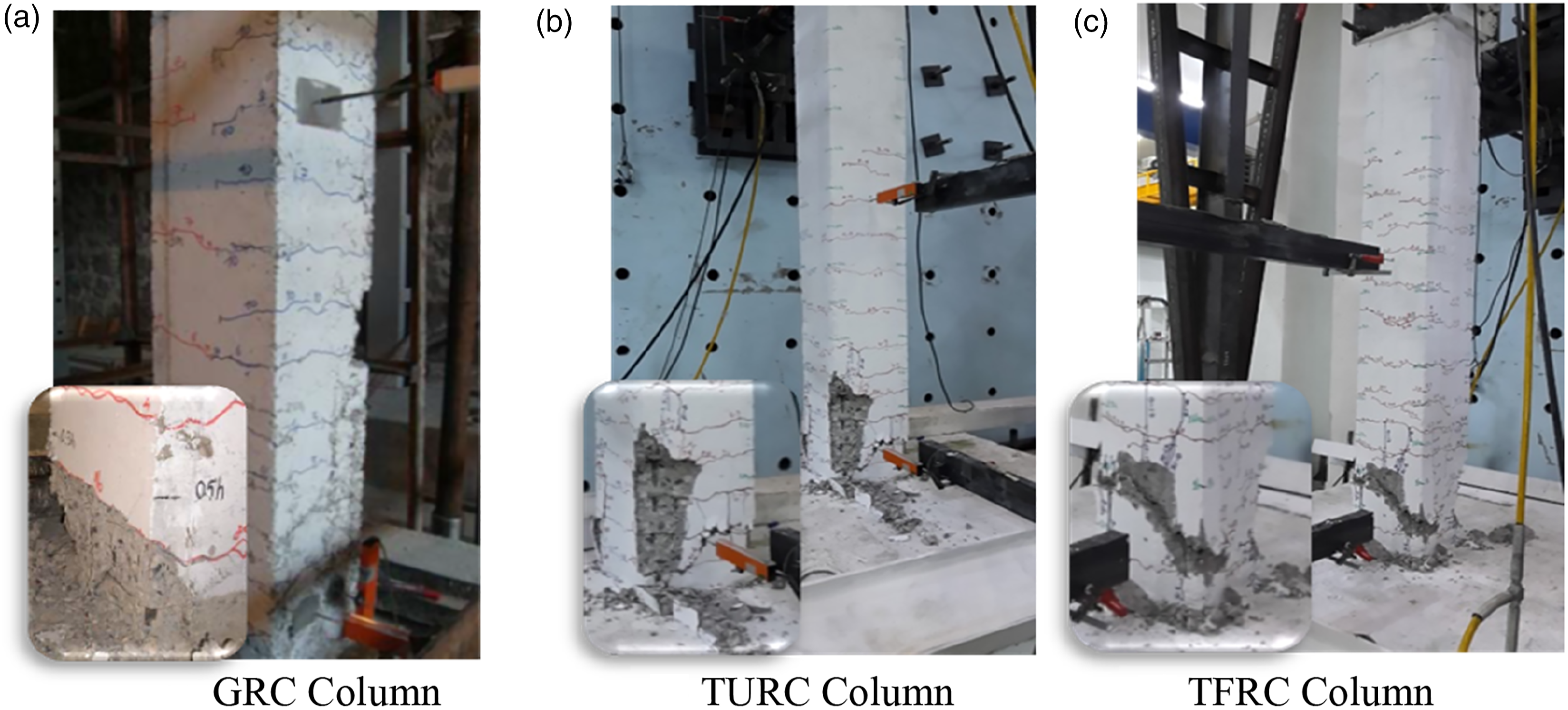
The following equation for the plastic hinge length Lp for rectangular RC columns was proposed (Paulay and Priestley, 1992)
Here; h is column height, d b is the diameter of longitudinal reinforcement and f y is yield strength of longitudinal reinforcement. Lengths of plastic hinge of test columns are ≈320 mm. A clear view of the plastic hinge formations clearly shows that the columns exhibit flexure behavior. In addition, in the following subheading of SSE, it is shown that the behavior develops as bending moment dominant.
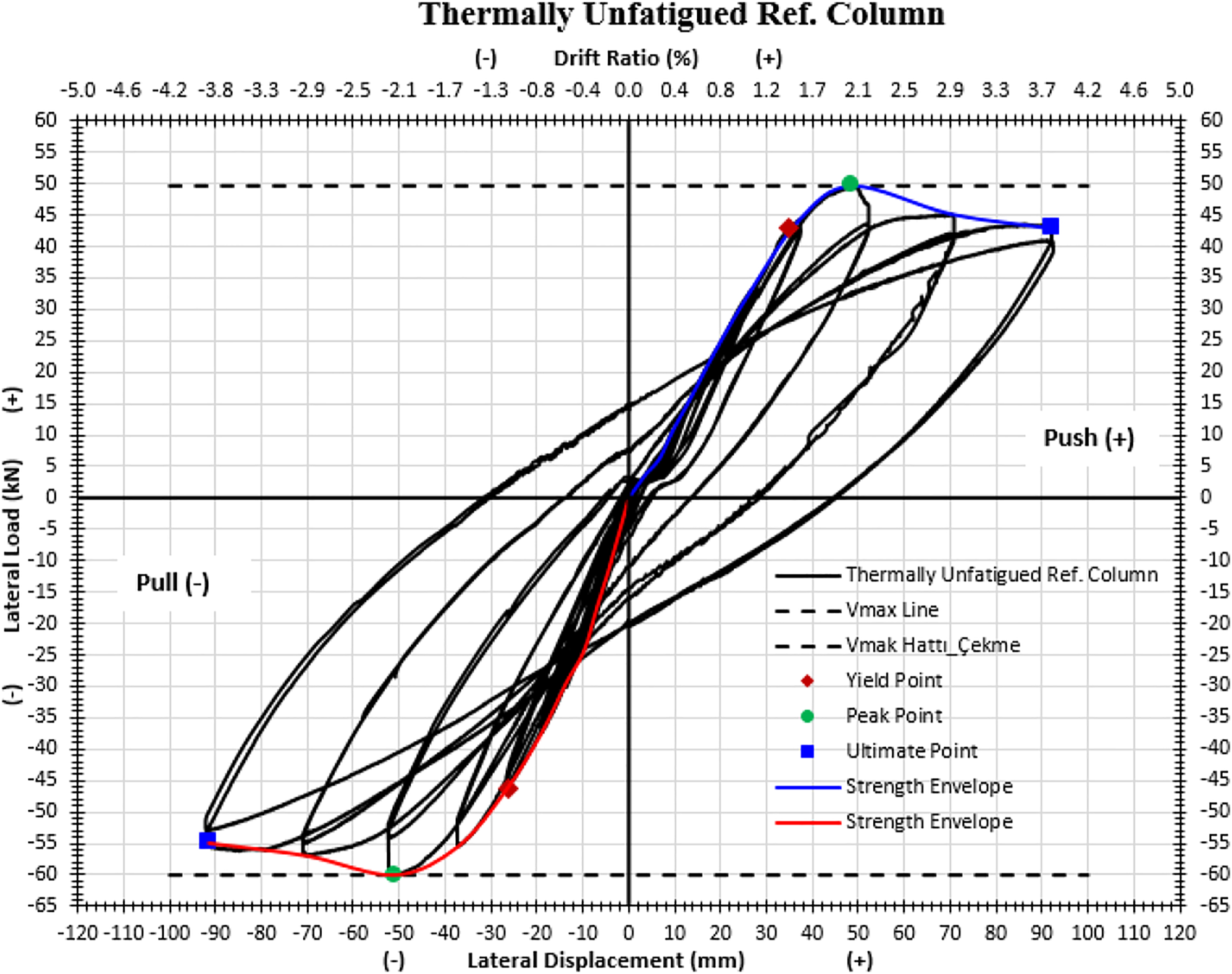
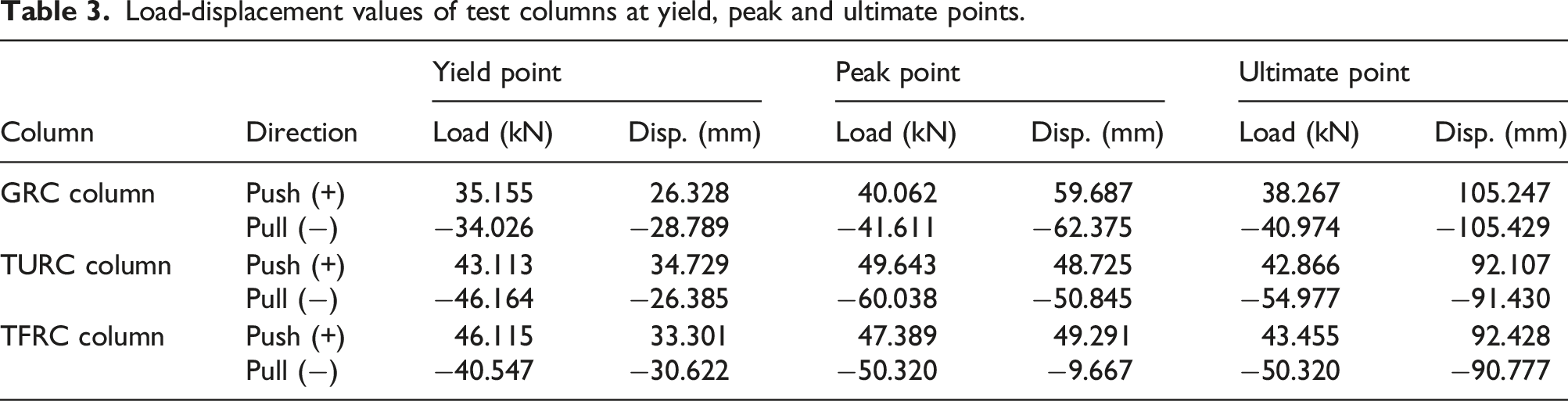
The hysteresis curves of the columns can be seen in Figures 14–16 and the strength envelopes can be seen in Figure 14. While the hysteresis curves and strength envelopes of the columns were evaluated, the loading step where the load decreased to 80% after the peak load was considered as the last step. Cross-section dimensions and reinforcement ratios of the columns are the same. The GRC column was produced the same material with the same reinforcement details as the TURC and TFRC columns and cured under the same conditions, but it is used in another experimental study (Yağmur, 2012). Therefore, the loading protocol of the GRC column was applied with load control and is not the same as other columns with displacement control. This situation does not prevent the comparison of some mechanical properties of the test columns. The peak loads of the GRC column are lower than other columns, while the peak point displacements are greater. When the values of yield point are compared, the GRC column passes into the plastic deformation zone at a smaller load and displacement level. Thermally unfatigued RC is the column with the largest load level at the points of yield, peak and ultimate in the pull direction, besides, the column has the largest peak load in the push direction. Thermally fatigued RC is the largest load level at the points of yield and ultimate in the push direction. Load and displacement values of the TURC column and TFRC column at critical points are not very different from each other. The numerical values of the yield, peak and ultimate points of the test columns are given in Table 3. Hysteresis curve and strength envelopes of gapless reinforced concrete column. Hysteresis curve and strength envelopes of thermally unfatigued reinforced concrete column. Hysteresis curve and strength envelopes of thermally fatigued reinforced concrete column. Load-displacement values of test columns at yield, peak and ultimate points.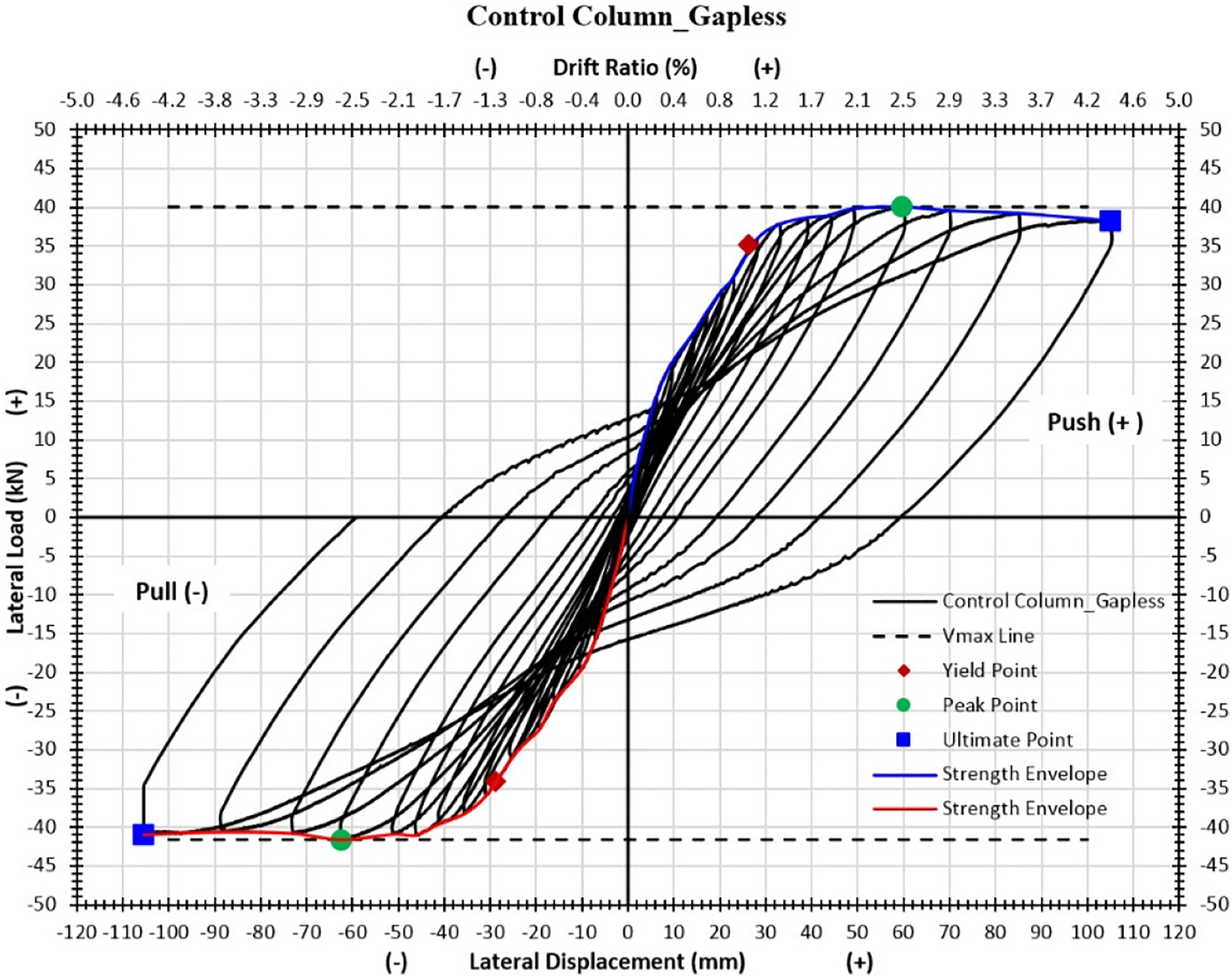

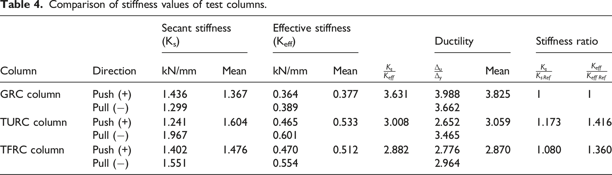
Stiffness evaluation
Stiffness is an important parameter for the behavior of the columns under the effect of lateral load. A structural element must have sufficient stiffness in terms of earthquake-resistant structure design. In this study, the secant and effective stiffness of the test columns were considered and compared. Secant stiffness (K
s
) is the slope of the K
y
line that passes at the level of 75% of the peak load, and effective stiffness (K
eff
) is the slope of the line combining the origin point and ultimate point. Since the performance of the test columns was evaluated in this study, effective stiffness was calculated by considering the ultimate point. Furthermore, in the ADRS (Acceleration Displacement Response Spectrum) diagram for displacement-based design, the response spectra of the test columns do not intersect with the spectrum curve. So, the design point can be considered at the ultimate point where the load drops to the level of 80%. The secant and effective stiffness of the columns are given in Figures 17–19. Secant and effective stiffness of gapless reinforced concrete column. Secant and effective stiffness of thermally unfatigued reinforced concrete column. Secant and effective stiffness of thermally fatigued reinforced concrete column.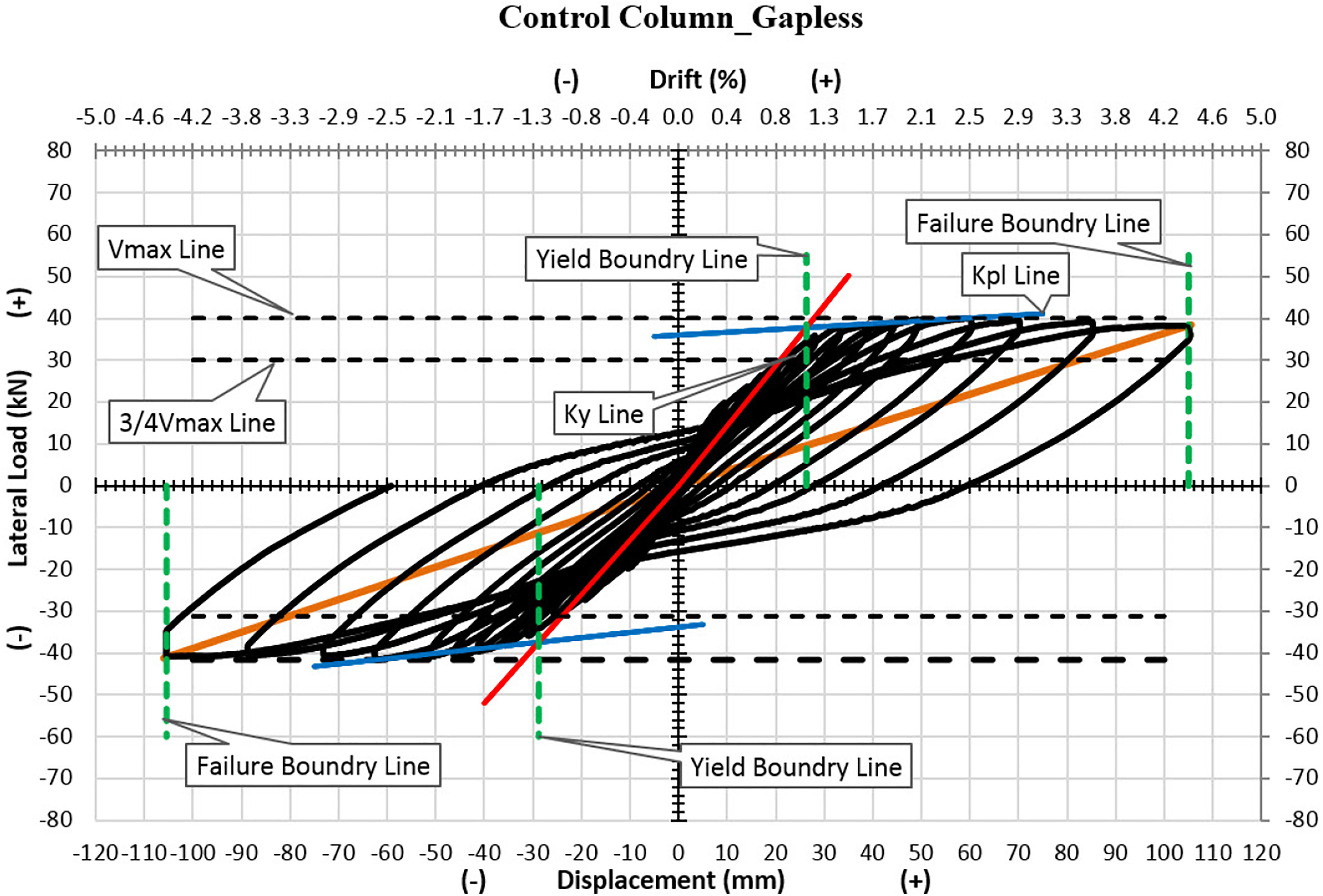
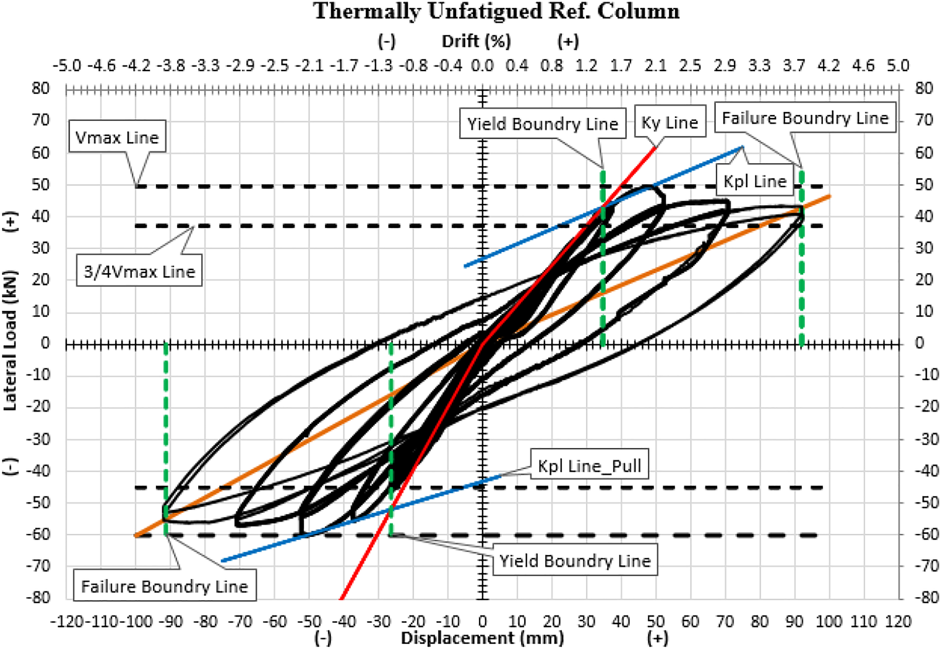
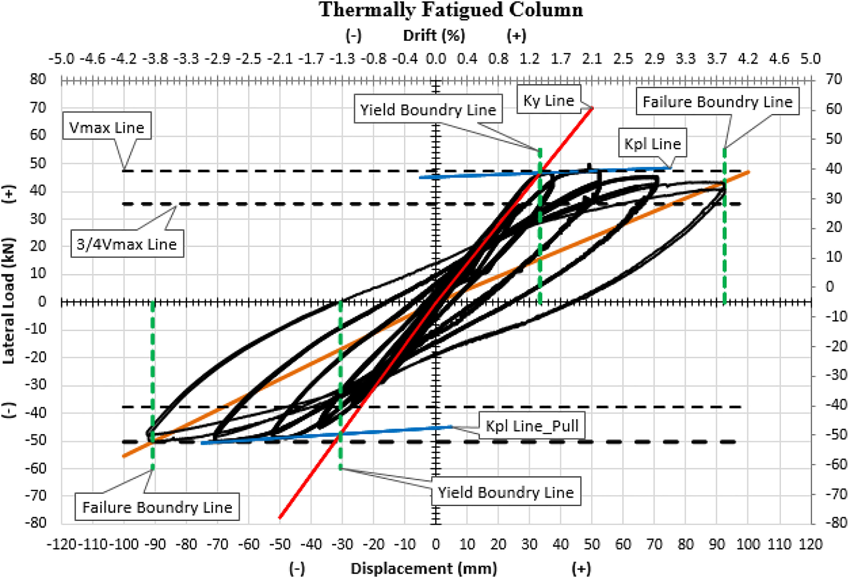
Comparison of stiffness values of test columns.
SSE
Many researchers have been studying in the evaluation of the shear strength of RC and most of these studies are mainly obtained by testing the columns. By evaluating the obtained results, the SSE are formed for RC columns where the contribution of concrete to shear strength is expressed depending on some parameters (Kim et al., 2012). The most important design parameters considered for the contribution of concrete to shear strength are namely; aspect ratio (l/h), displacement ductility (μ), AL level (P), longitudinal reinforcement ratio (ρ t ), dimension effect and effective shear area (A sh ). In most models, the effective shear area is considered to be 80% of the gross cross-sectional area (A g ) of the column, whereas in some it is expressed as the section width (b w ) multiplied by the useful height (d). (A sh = 0,80A g or A sh = b w d).
The shear strength of RC columns within the framework of the contribution of concrete, shear reinforcement and AL were evaluated (Priestley et al., 1994). They defined the decrease in shear strength of concrete based on increasing ductility with following equation
Here the factor of γ is 0.29 if the displacement ductility (μ) is less than 2, and is 0.10 if it is greater than 4. The factor of γ decreases linearly when ductility is between 2 and 4.
A few years later, when the seismic performance of high-strength concrete columns was investigated, it was found that the contribution of concrete to the shear was reduced dramatically (Xiao and Martirossian, 1998). Accordingly, the factor of γ was defined by the following equations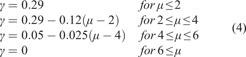
Recently, the change in ductility in relation to the longitudinal reinforcement ratio and concrete strength were evaluated in a numerical parameter study (Howser et al., 2010). Therefore, the determination of the factor of γ and accordingly the contribution of concrete to the shear has been revised by considering both the strength and the longitudinal reinforcement of the cross-section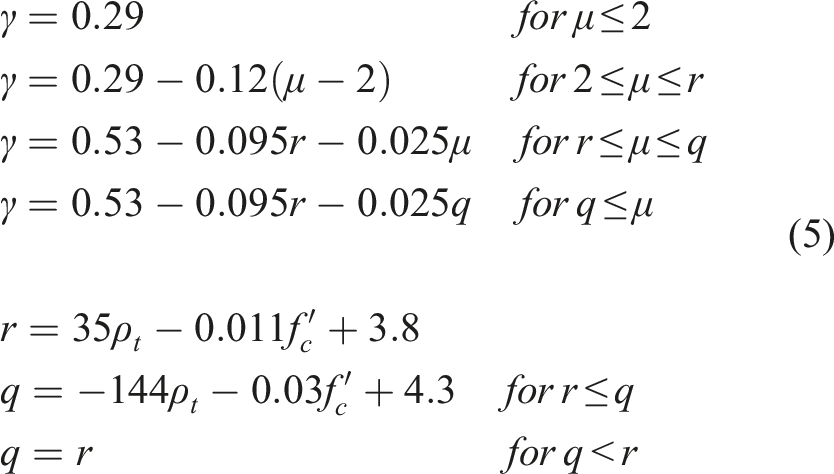
The fact that the strength envelopes of the columns intersect the SSE indicates that shear dominates the behavior and the columns fail by reaching the shear strength. If the strength envelope decreases with a high slope after the peak load without intersecting with the SSE, this indicates that the column fails abruptly before reaching the expected shear strength. This situation occurs when the quality of the concrete is lower than expected and again describes a shear failure situation. Figure 20 shows the SSEs of the columns and the strength envelope curves reduced to the axis of the ductility. It is seen that the strength envelopes of the test columns did not intersect the SSE and there was no sudden load reduction after the peak load. All of the columns fully exhibit a flexural behaviour which is far from reaching the shear strength. In the TURC and TFRC columns, the steel pipe did not prevent the flexural behavior and did not cause brittle failure due to the sudden increase in shear strength. Strength envelopes and shear strength envelopes.
Energy consumption
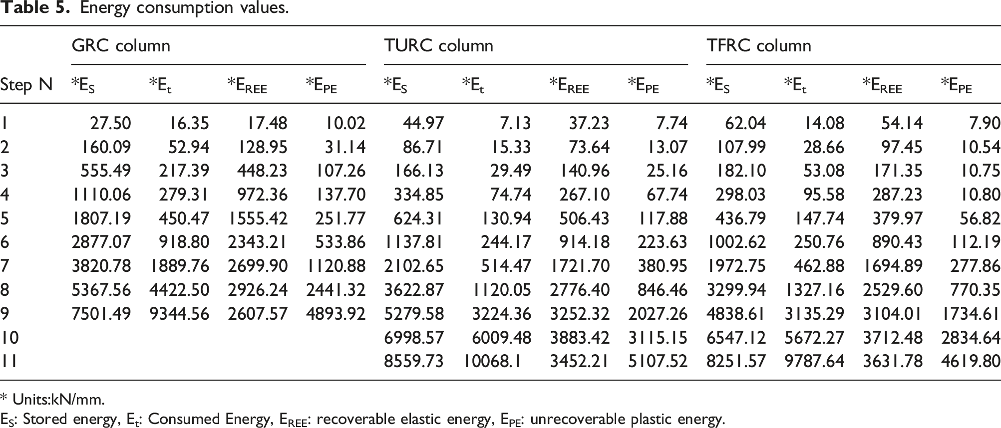
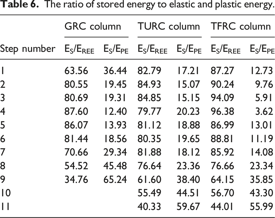
Energy consumption capacity is an important parameter for evaluating the performance of columns which are very important carrier system elements in RC frame and/or composite systems. Energy consumption of columns depends on AL level, yield displacement, number of cycles, support conditions, cross-section detail, characteristic properties of material and reached peak load. Figure 21 provides visual descriptions of energy consumption zones. There was no significant difference between the amounts of energy consumption per step of the columns. The energy consumption of the TURC and TFRC columns begins to separate significantly from the GRC column, especially after the yield point (Figure 22). Figure 22 shows the consumed energy per step (Et) and recoverable elastic energy (EREE) of the columns visually. The numerical values of the energy consumption of the columns are given in Table 5 and the percentage values of the energy consumption rates are given in Table 6. The amount of consumed energy after the yield point in the columns increases considerably compared to previous cycles. However, there are no big differences between the energy consumption values of the columns. This shows that the steel pipe used in the middle of the cross-section of the column and the thermal cycle do not adversely affect the performance of the column and that the proposed heating system can be used. The ratio of recoverable elastic energy (E
REE
) to the stored energy (E
S
) at each step in the columns is 80%–95% before the yield, while it decreases in the plastic phase cycles and ultimately decreases to 35%–44%. Similarly, the ratio of plastic energy (Ep) to the stored energy (E
S
) is 13.93%, 23.36% and 23.34% for the GRC, TURC and TFRC columns at the yield point respectively, after the yield point these ratios increased by 65.24%, 59.67% and 55.99% in the last cycles. Therefore, all of the columns exhibited plastic deformation by consuming energy effectively until they reached their capacity. Energy consumption zones. Consumed and recoverable elastic energies of test columns per step. Energy consumption values. * Units:kN/mm. ES: Stored energy, Et: Consumed Energy, EREE: recoverable elastic energy, EPE: unrecoverable plastic energy. The ratio of stored energy to elastic and plastic energy.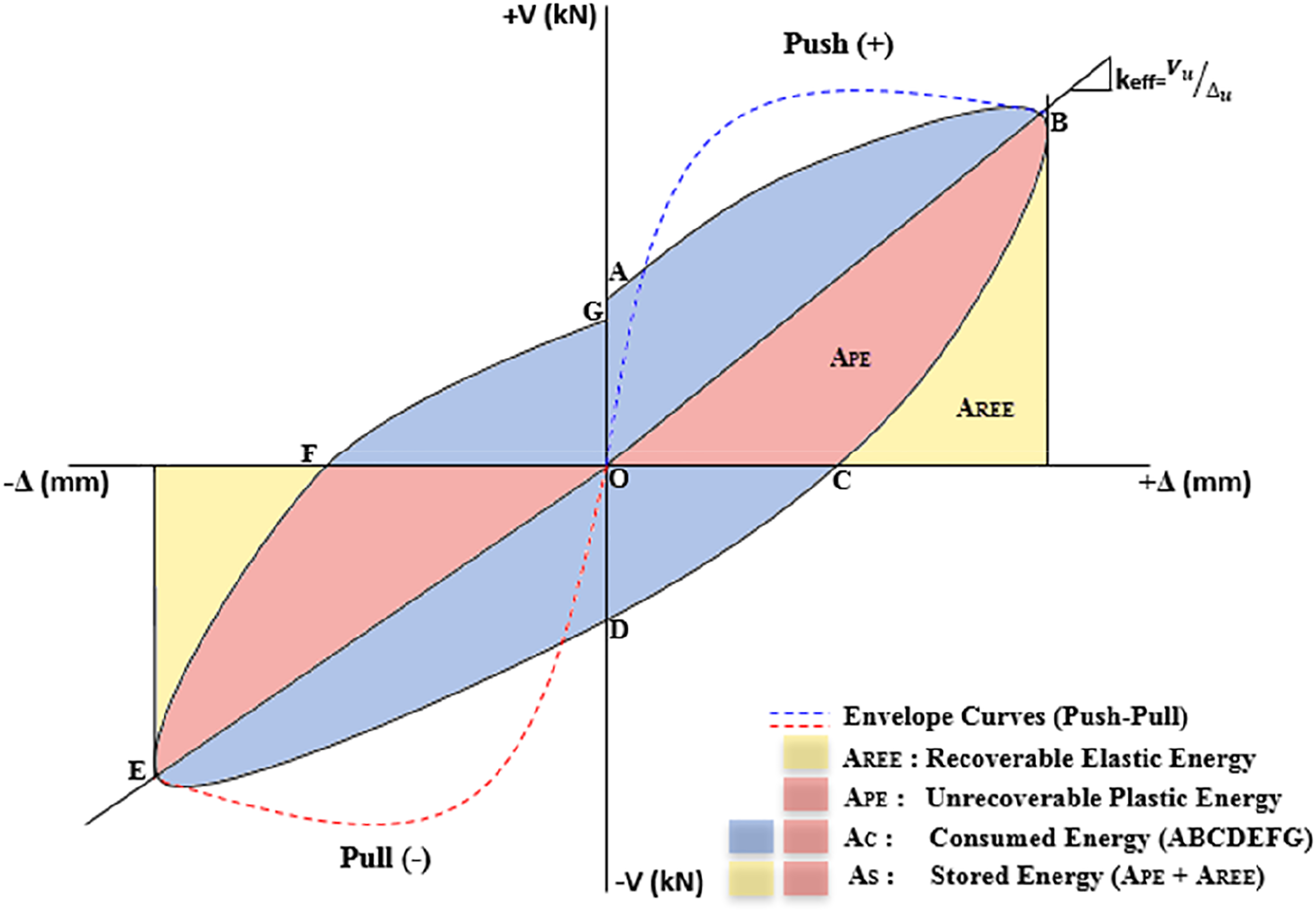

Conclusions
Within this study, thermal fatigue behaviour of RC columns, which are used in the heating and storage of the required thermal energy to heat the reinforced concrete buildings, was investigated experimentally by lateral cyclic loading test. Also the effect of thermal cycling on the concrete material tried to be observed. The main conclusions are summarized in this section.
Concrete material inside the column penetrating the hot steel pipe showed similar results accepted for the cement matrix investigated under thermal cycling effect in literature. According to the mechanical test results, placing a steel pipe in the center of the classical column does not create significant differences in mechanical performance. In fact, it can be stated that columns with steel pipes have better performance. This situation can be explained as the reducing effect of the gap can be easily tolerated by the increasing effect of the steel material. The hysteretic behavior of the three RC columns was compared with strength envelopes, stiffness parameters, SSE, and energy consumption capacities. There was no significant difference between the results in terms of these parameters. All of the columns exhibited flexural-dominant behavior. Gapless RC has the highest ductility. However, the TURC and TFRC columns are able to perform up to a drift ratio of 3.9%. This ratio is quite sufficient for the design of the columns in a carrier system. The performance of the TURC column is better than other columns in terms of strength, stiffness, and energy absorption capacity. However, the performance of the TFRC column is very close to the TURC column in terms of these parameters. In this case, thermal fatigue causes a slight decrease in the performance of the column. However, this performance loss caused by thermal fatigue is not in a significant level. Therefore, the mechanical performance of the column that is subjected to thermal fatigue (with 1378 cycle and temperatues lower than 100°C) can be considered successfull.
The proposed heating method is a new approach. The obtained results of thermal analysis (Ozrahat and Unalan, 2017) and mechanical test results are encouraging. However thermal stress levels for different cross-sections, aspect ratios and ALs, working temperatures and cycles should be investigated in detail. An important parameter is the fatigue life of the column. Future study should be conducted on thermal fatigue life prediction of structural hollow RC.
In addition, in this study the mechanical behaviour of RC was investigated after a certain number of thermal cycles. This aproach gave us important information about the thermal fatigue effect of thermal cycling. However, in the following stages of the proposed system, structural strength and thermal cycling should be considered simultaneously. At this point thermomechanical coupling analysis gaining importance and should be conducted as future work where more parameters and test elements will be taken into account.
Besides, the proposed new system will make a significant contribution to the solution of problems related to conventional fan and radiator heating systems such as insufficient thermal comfort, causing useless areas in living spaces and causing visual pollution.
Footnotes
Author contributions
All authors contributed to the study conception and design. Material preparation, data collection and analysis were performed by Evrim Özrahat, Tamer Dirikgil and Sebahattin Ünalan. All authors read and approved the final manuscript.
Declaration of conflicting interests
The author(s) declared no potential conflicts of interest with respect to the research, authorship, and/or publication of this article.
Funding
The author(s) disclosed receipt of the following financial support for the research, authorship, and/or publication of this article: This study was supported by Erciyes University Scientific Research Project Unit with FDK 2014-4961 project code.