




Abstract
A carbon-fiber-reinforced polymer (CFRP) sheet is wrapped around the basalt-fiber-reinforced polymer (BFRP) to develop a hybrid carbon/basalt-fiber-reinforced polymer (C/BFRP) so as to protect the basalt fibers in touch with chloride ions. Tensile testing is conducted on the BFRP and hybrid C/BFRP sheets. The effect of the durability of the fiber-reinforced polymer sheet on the behavior of the seawater–sea sand concrete (SSC) columns confined by the BFRP and hybrid C/BFRP sheets is examined using axial compression testing. The tensile strength retention and elongation at break retention of the hybrid C/BFRP sheet improve by 41% and 24% higher than those of the BFRP sheet after 12 months in seawater. The ultimate strength of the BFRP-confined SSC column decline by 40% more than those of the hybrid C/BFRP-confined SSC column respectively, after 12 months of seawater immersion, resulting from the reduction of lateral pressure provided by the BFRP and hybrid C/BFRP sheets in seawater. A formula for calculating the long-term ultimate strength and ultimate strain of the FRP-confined SSC column is proposed, and its predictions agree well with the test results. The hybrid C/BFRP sheet proves more efficient than the BFRP sheet in confining the seawater–sea sand concrete columns.
Keywords
Introduction
Seawater–sea sand concrete (SSC) is an alternative to standard concrete in marine structures and solves the shortage of river sand and freshwater (Guo et al., 2020; Wei et al., 2021). However, chloride ions penetrate SSC and corrode steel, reducing the service life of marine structures (Guo et al., 2018). Basalt-fiber-reinforced polymer (BFRP) has a high strength-to-weight ratio and excellent corrosion resistance, so it is considered an alternative to steel for enhancing the durability of steel–SSC composites. Although the matrix resin is immune from chloride ions, the Fe2+ ions in the basalt fibers may react with them (Wang et al., 2017b; Zhang et al., 2020). Therefore, a carbon-fiber-reinforced polymer (CFRP) sheet was coated on BFRP to prevent it from deteriorating by chloride ions.
Concrete columns confined by BFRP can significantly improve their ultimate compressive strength and ultimate compressive strain (Li et al., 2016; Li and Wu, 2023). The confining pressure increases proportionally with the lateral expansion of the column until the rupture of the BFRP sheet. The lateral stiffness of the BFRP sheets (their elastic modulus multiplied by their thickness) primarily influences the ultimate strength and ultimate strain of the concrete columns confined by BFRP sheets. Increasing the BFRP layers from one to two enlarges the compressive strength and ultimate strain of BFRP-confined columns by 27.6% and 107.3% respectively (Huang et al., 2020). The ultimate strain linearly enlarges with an increase in the lateral stiffness, i.e., the thickness of the FRP sheet multiplied by its elastic modulus. Increasing the CFRP sheets from one to three improves the ultimate strain by 260% (Zhou et al., 2016).
Using seawater–sea sand concrete to replace ordinary concrete insignificantly affects FRP-confined concrete columns (Yang et al., 2021). The mechanical behavior of FRP-confined SSC columns is similar to that of FRP-confined ordinary concrete columns (Zeng et al., 2020). The stress–strain responses of FRP-confined SSC columns are typical bilinear stress–strain curves. The linear elastic stage of the compressive stress–strain curve primarily depends on the plain concrete column (Xiao and Wu, 2000), and the effects of the dilation of the concrete and the lateral pressure provided by the FRP sheet on the hardening branch of the compressive stress–strain curve are significant.
The mechanical properties of FRP-confined concrete columns immersed in seawater degrade due to the deterioration of the tensile properties of FRP sheets. The ultimate strength of BFRP-confined SSC columns declines by 42% after 12 months of immersion in a marine environment (Bazli et al., 2021), while that of CFRP-confined concrete columns decreases by 9.7% after 3 years of immersion in seawater (Gharachorlou and Ramezanianpour, 2010). The compressive strength of ordinary concrete and SSC drops by 15% and 4% respectively, after 8 months of seawater immersion (Santhanam et al., 2006). Thus, compared to the degradation of concrete, the FRP sheet degrades more severely in seawater. The tensile strength of BFRP and CFRP sheets declines by 21% and 5% respectively, after 66 days of seawater immersion (Wu et al., 2015).
The mechanical properties of the CFRP sheet deteriorate less than those of the BFRP sheet (Lu et al., 2023; Wei et al., 2021). The tensile strength and elongation at break of the BFRP sheet decrease by 9.76% and 16.3% respectively, but its elastic modulus increases by 3.24% after 150 days of seawater immersion (Yang et al., 2010). Water molecules diffuse into the matrix resin and hydrolyze it, resulting in the propagation of microcracks. Chloride ions react with the Si–O–Si bonds of basalt fibers through microcracks, reducing their tensile strength (Wang et al., 2017a). The mechanical synergy between the fiber and the resin also declines. It is proven that the seawater resistance of CFRP sheets is better than that of BFRP sheets. In fact, the tensile strength of CFRP sheets decreases only by 0.91%, but its tensile modulus increases by 3.87% after seawater immersion for 150 days (Kafodya et al., 2015). However, CFRP sheets are more expensive than BFRP sheets. Thus, hybrid BFRP–CFRP sheets can be used to confine SSC columns and satisfactorily balance the cost, mechanical properties, and durability. Compared with BFRP, the tensile strength and tensile modulus of hybrid C/BFRP increase by 18.8% and 82.4% respectively (Wu et al., 2010). Compared with CFRP, the elongation at break of hybrid C/BFRP improves by 20.3% (Wang et al., 2014).
This work investigates the effects of seawater on BFRP-confined and hybrid C/BFRP-confined seawater–sea sand concrete columns. The relationship between the degradation of the BFRP and hybrid C/BFRP sheets and the variation in the compressive stress–strain behavior of the columns is also examined. Further, a model is proposed to predict the ultimate compressive stress and ultimate strain on the BFRP-confined and hybrid C/BFRP-confined SSC columns immersed in seawater.
Experimental procedures
Raw materials
The mix proportion of the seawater–sea sand concrete.

The mix proportion of the prepared artificial seawater.

The properties of the fibers and the FRP sheets.
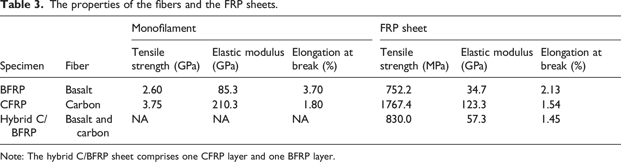
Note: The hybrid C/BFRP sheet comprises one CFRP layer and one BFRP layer.
Preparing FRP-confined SSC columns
Figure 1 illustrates the preparation of an FRP-confined SSC column. The plain seawater–sea sand concrete column with a diameter of 150 mm and a height of 300 mm was cast. The two FRP jackets included 1) a three-ply BFRP sheet with a thickness of 2.01 mm and 2) a one-ply CFRP sheet wrapped around a two-ply BFRP sheet, giving rise to a total thickness of 1.74 mm. The impregnating resin was Sika 330CN. The overlapping length of the FRP sheet was set at 150 mm to prevent premature failure. The FRP-confined SSC columns were cured in the laboratory for 7 days, and the compression test on the FRP-confined SSC columns was conducted at regular intervals. Twenty-four specimens were prepared, including sixteen FRP-confined SSC columns and eight plain SSC columns. Table 4 presents the details of the specimens. Preparing an FRP-confined SSC column: (a) the wet lay-up of the FRP sheet; (b) strengthening the column with an FRP sheet. The details of the plain and FRP-confined SSC columns. Note: The letter P indicates the plain SSC column; the letters B and C/B represent the BFRP and hybrid C/BFRP sheet respectively; “Control” denotes the reference specimens without seawater immersion; the terms 4M, 8M, and 12M stand for an immersion period of 4, 8, and 12 months respectively.

Exposure conditions
All the aged specimens were immersed in the artificial seawater, with the mix proportion listed in Table 2. The concentration of the artificial seawater increased owing to water evaporation during the immersion period, and the artificial seawater was poured into the chamber every month.
Testing instrumentation
Figure 2 illustrates the photo and schematical diagram of the testing setup. The axial compression deflection was measured using 20 mm linear variable differential transformers (LVDTs). Two LVDTs were evenly distributed around the column, and the LVDTs were mounted on the steel frame fixed on the concrete. The clear span of the steel frame was 120 mm. Strain gauges BX120-50AA were adopted to measure the hoop strain of the plain and FRP-confined SSC columns. Four strain gauges were horizontally bonded to the surface of the concrete and the FRP sheet at the middle height of the column. A JM3841 data logger recorded deflection and strain, and the collection frequency was 1 Hz. The top and bottom of the column were premature to failure because of stress concentration, so a CFRP strip with a width of 50 mm strengthened the top and bottom of the concrete. According to ASTM C469-14, a universal testing machine (MATEST C088-01) applied the load at a displacement rate of 0.18 mm/min. The (a) photo and (b) schematical diagram of the testing setup.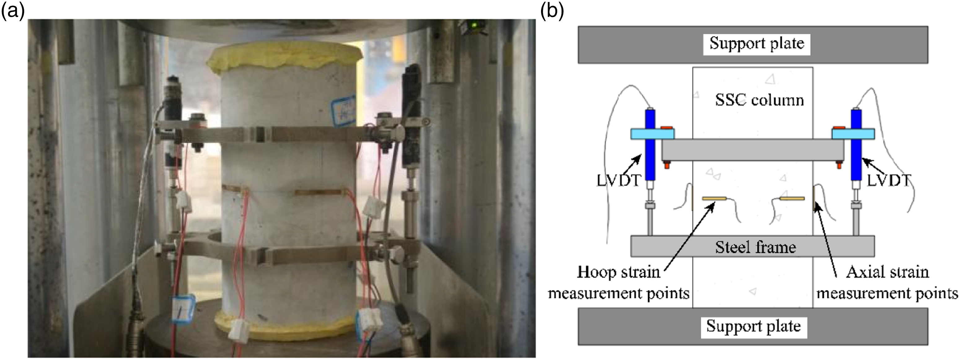
Results and discussion
Effects of seawater on properties of BFRP and hybrid C/BFRP sheets
Figure 3(a) shows the effects of the seawater on the tensile stress-strain behavior. The tensile stress linearly increases with the strain until the tensile rupture. Figure 3(b) delineates the effect of seawater immersion on the tensile strength of the BFRP and hybrid C/BFRP sheets. The tensile strength of the BFRP sheet decreases with an increase in the immersion period. The tensile strength of the BFRP sheet drops by 40.7% after 4 months of immersion and then remains stable. It is reported that the tensile strength of BFRP sheets depends on basalt fibers (Lu et al., 2016). Microcracks form owing to the plasticization and hydrolysis of the matrix resin of BFRP sheets after water absorption, and OH– ions leaching from SSC through the cracks react with the Si–O–Si bonds of basalt fibers as follows (Wang et al., 2017b): The effect of seawater immersion on the (a) tensile stress-strain behavior, (b)tensile strength, (c) elastic modulus, and (d) elongation at break of the BFRP and hybrid C/BFRP sheets.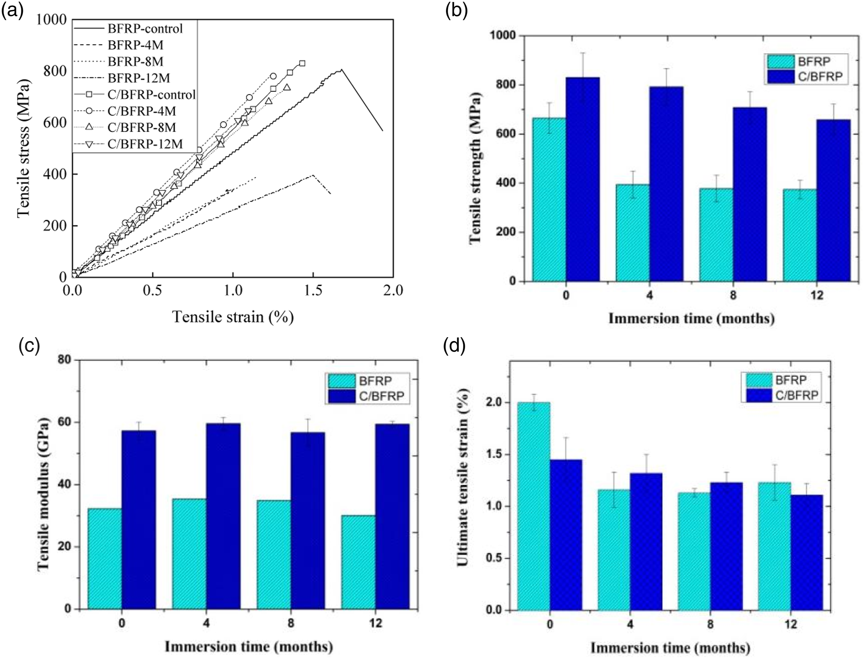
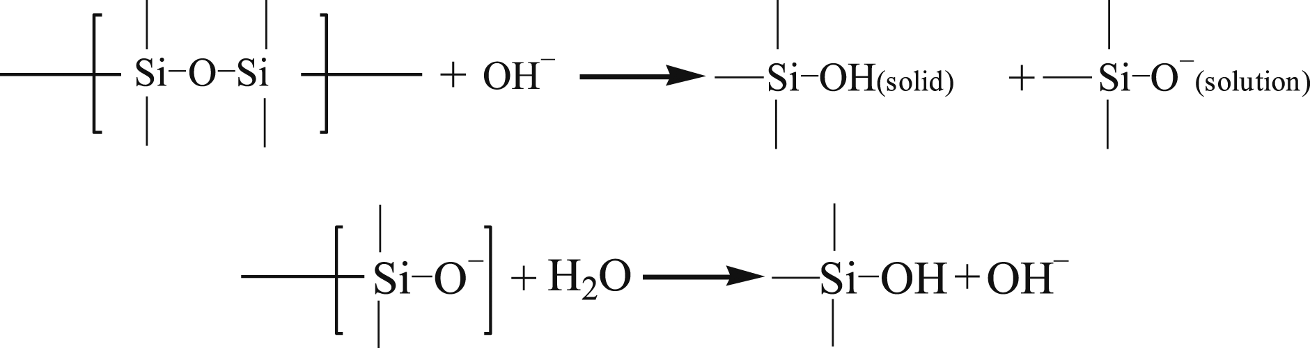
An SiOH gel is less dense than the structure with Si–O–Si bonds, so seawater can diffuse through the gel. In addition to the deterioration of Si–O–Si bonds by OH– ions, Cl– ions in seawater degrade basalt fibers according to the following chemical reactions (Wei et al., 2011).
Fe2+ + Cl– → [FeCl complex]–
[FeCl complex]– + OH– → Fe(OH)2 + Cl–
Fe(OH)2 + O2 + H2O → Fe(OH)3 → Fe2O3·nH2O
The final reaction product of rust (Fe2O3·nH2O) easily absorbs more water molecules, expanding the matrix resin, thereby forming more microcracks and degrading the BFRP sheet.
Figure 3(b) shows that the tensile strength of the hybrid C/BFRP sheet decreases as the immersion period extends. Compared to the control hybrid C/BFRP sheet, the tensile strength of the hybrid C/BFRP sheet drops by 4.6%, 14.7%, and 20.7% after an immersion period of 4, 8, and 12 months respectively. Compared to the BFRP sheet, the tensile strength of the hybrid C/BFRP sheet improves by 25%, 101%, 87%, and 76% for an immersion period of 0, 4, 8, and 12 months respectively, indicating that the effect of the CFRP on enhancing the tensile strength of the hybrid C/BFRP sheet is significant. The carbon- and basalt-fiber-reinforced polymer sheets of tension test was carried out, and the tensile strength of the carbon- and basalt-fiber-reinforced polymer sheets declines by 19% and 44% respectively, after 12 months of immersion in seawater, which implies that the primary deterioration of the hybrid C/BFRP sheet results from the degradation of the BFRP. Compared to the BFRP sheet in seawater, only one side of the BFRP in the hybrid C/BFRP sheet contacts seawater, and the CFRP sheet prevents the other side of the BFRP from deteriorating by seawater.
Figure 3(c) demonstrates the effect of seawater immersion on the elastic modulus of the BFRP and hybrid C/BFRP sheets. In the case of the control FRP sheet, the tensile elastic modulus of the hybrid C/BFRP sheet is 77% higher than that of the BFRP sheet, attributed to the higher elastic modulus of CFRP than BFRP in the hybrid C/BFRP sheet. In the case of the aged fiber-reinforced polymer sheets, the variation in the elastic modulus of the BFRP sheet and the hybrid carbon/basalt-fiber-reinforced polymer sheet within 12 months of immersion in seawater ranges from –6.8% to 9.6% and from –0.1% to 4.0% respectively, which indicates that the impact of seawater on the elastic modulus of the BFRP sheet is severer than that on the elastic modulus of the hybrid C/BFRP sheet. Compared to the variation of the tensile strength in Figure 3(a), the effect of seawater immersion on the elastic modulus of both BFRP and hybrid C/BFRP sheets is insignificant. Seawater deteriorates the fiber structure, reducing the tensile strength of the FRP sheets more severely than their elastic modulus (Lu et al., 2020).
Figure 3(d) depicts the effect of seawater immersion on the elongation at break, or the fracture strain, of the BFRP and hybrid C/BFRP sheets. The elongation at break of both BFRP and hybrid C/BFRP sheets decreases as the immersion period extends, and the extent of reduction in the fracture strain of the hybrid C/BFRP sheet is less than that of the BFRP sheet. Compared to the control specimens, the elongation at break of the BFRP sheet declines by 42.0%, 43.5%, and 38.5% after 4, 8, and 12 months of immersion in seawater respectively, while that of the hybrid C/BFRP sheet drops by 9.0%, 15.2%, and 23.4% after 4, 8, and 12 months respectively, which is because basalt fibers embrittle in seawater due to corrosion, and the defects in the basalt fiber surface cause them to easily fracture under tensile loading.
Failure mode of columns
Figure 4(a) and 4(b) shows the failure mode of the plain seawater–sea sand concrete columns. Vertical splitting cracks cause the control and aged plain SSC columns to fail, which is attributed to the low tensile strength of concrete. The failure mode of the plain and FRP-confined SSC columns. (a) Ref-P (b) P-12M-S (c) Ref-B (d) B-12M-S (e) Ref-C/B (f) C/B -12M-S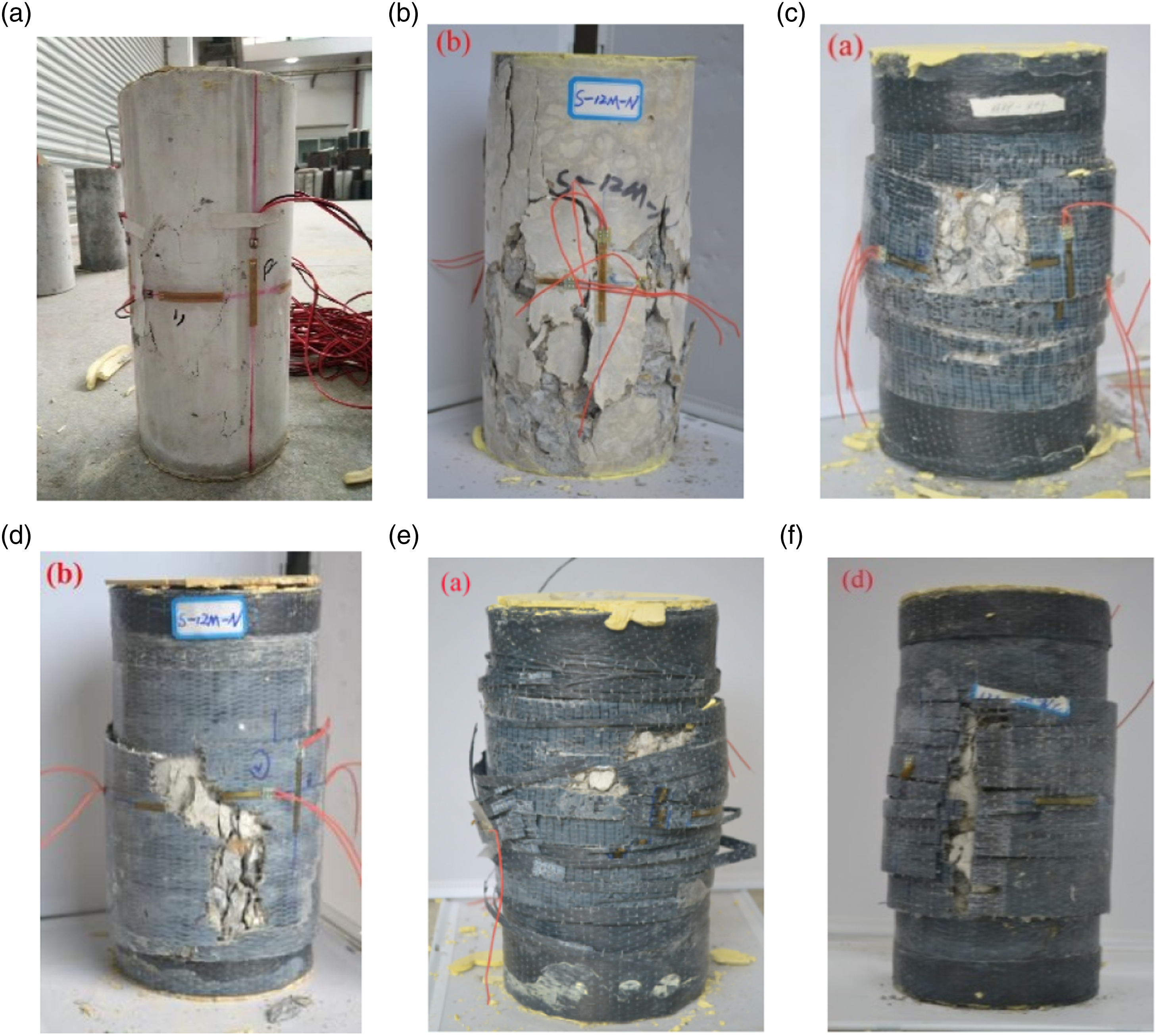
Figure 4(c) and 4(d) depicts the failure mode of the BFRP-confined SSC columns. Both the control specimen and the BFRP-confined SSC column immersed in seawater for 12 months fail because of the tensile rupture of the BFRP sheet at or near the mid-height and concrete spalling. The failure section of the BFRP sheet of the BFRP-confined SSC column immersed in seawater for 12 months is more irregular than that of the control BFRP-confined SSC column. Immersion in seawater for 12 months causes the debonding between the BFRP sheet and concrete. Such debonding may detrimentally impact the effectiveness of the confinement, and the core concrete can crush without the BFRP sheet being significantly stressed (El-Hacha et al., 2010), shifting the tensile failure of the BFRP sheet from the regular section to the irregular section.
Figure 4(e) shows that the failure mode of the control hybrid C/BFRP-confined SSC column is a combination of the delamination between the CFRP and BFRP sheets due to their incompatible deformation and the tensile failure of the hybrid C/BFRP sheet. The elongation at break of the BFRP sheet is higher than that of the CFRP sheet, causing the CFRP sheet to fail prior to the BFRP sheet and giving rise to the debonding between them after the failure of the CFRP sheet. Figure 4(f) shows the failure mode of the hybrid C/BFRP-confined SSC column immersed in seawater for 12 months. The delamination between the CFRP and BFRP sheets and the tensile failure of the hybrid C/BFRP sheet are observed, and the tensile failure of the hybrid C/BFRP sheet is primary. The bearing-capacity synergy between the CFRP and BFRP of the hybrid C/BFRP sheet immersed in seawater deteriorates. Once the CFRP sheet ruptures, the BFRP sheet separates.
Stress–Strain behavior of columns
Figure 5 delineates the stress–strain curves obtained from the compression tests. They can be divided into three regions. Stage I is the initial linear elastic branch, where the circumferential strain linearly increases with the axial stress on the column. Stage I of the stress–strain behavior is primarily controlled by the seawater–sea sand concrete, and the FRP sheet minimally affects the behavior of the SSC at low levels of axial compressive force. Stage II shows the nonlinear behavior, where the circumferential strain soars with the axial stress on the column, and the contribution of FRP to the axial compressive load bearing intensifies. Once the axial strain reaches the peak strain of the plain concrete, a linear strain-hardening section forms in stage III. The circumferential strain linearly enlarges with the axial stress on the column until the column fails. The stress–strain behavior of the (a) plain SSC column, (b) BFRP-confined SSC column, and (c) C/BFRP-confined SSC column.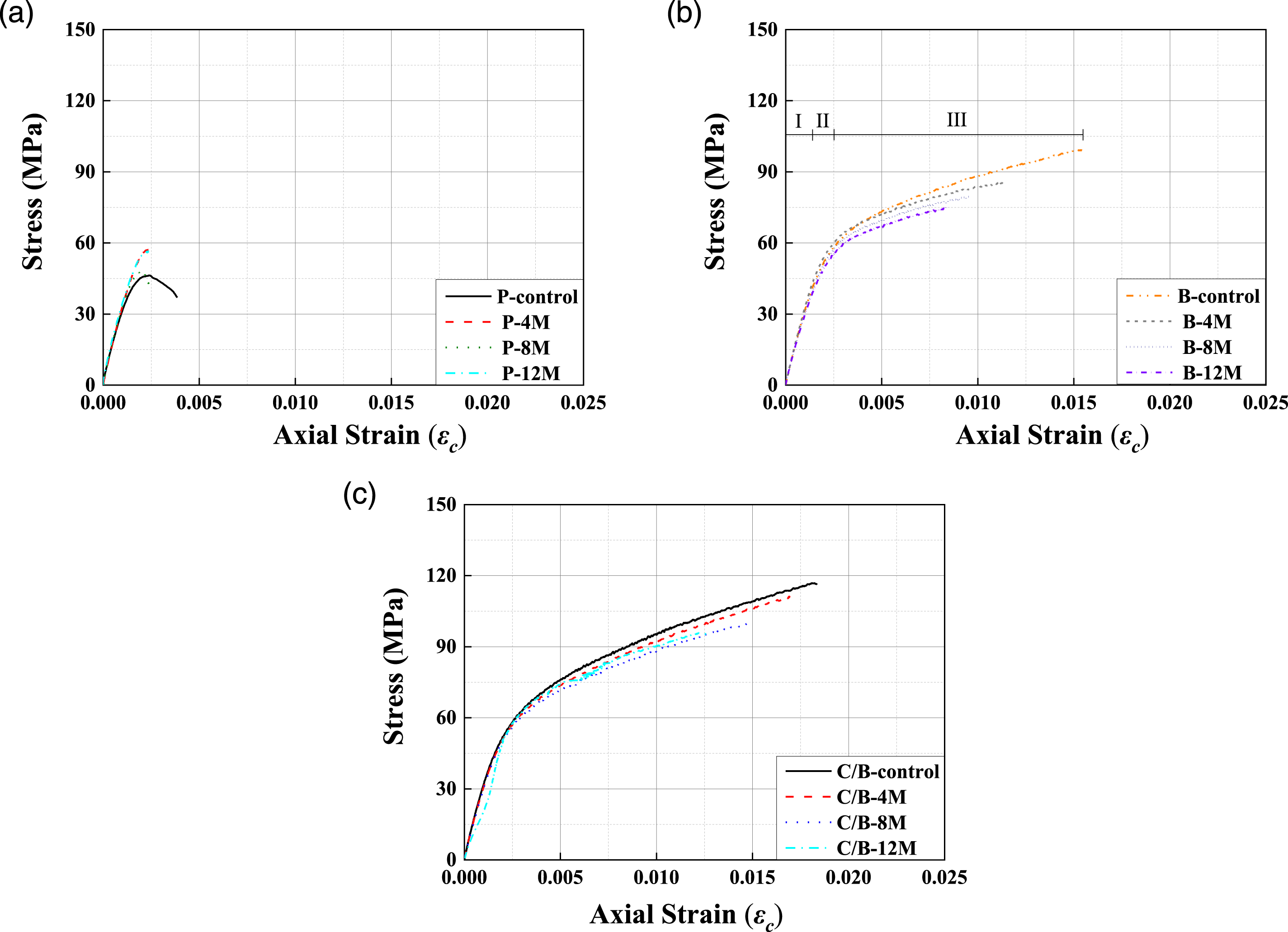
The critical properties of the plain and FRP-confined SSC columns.
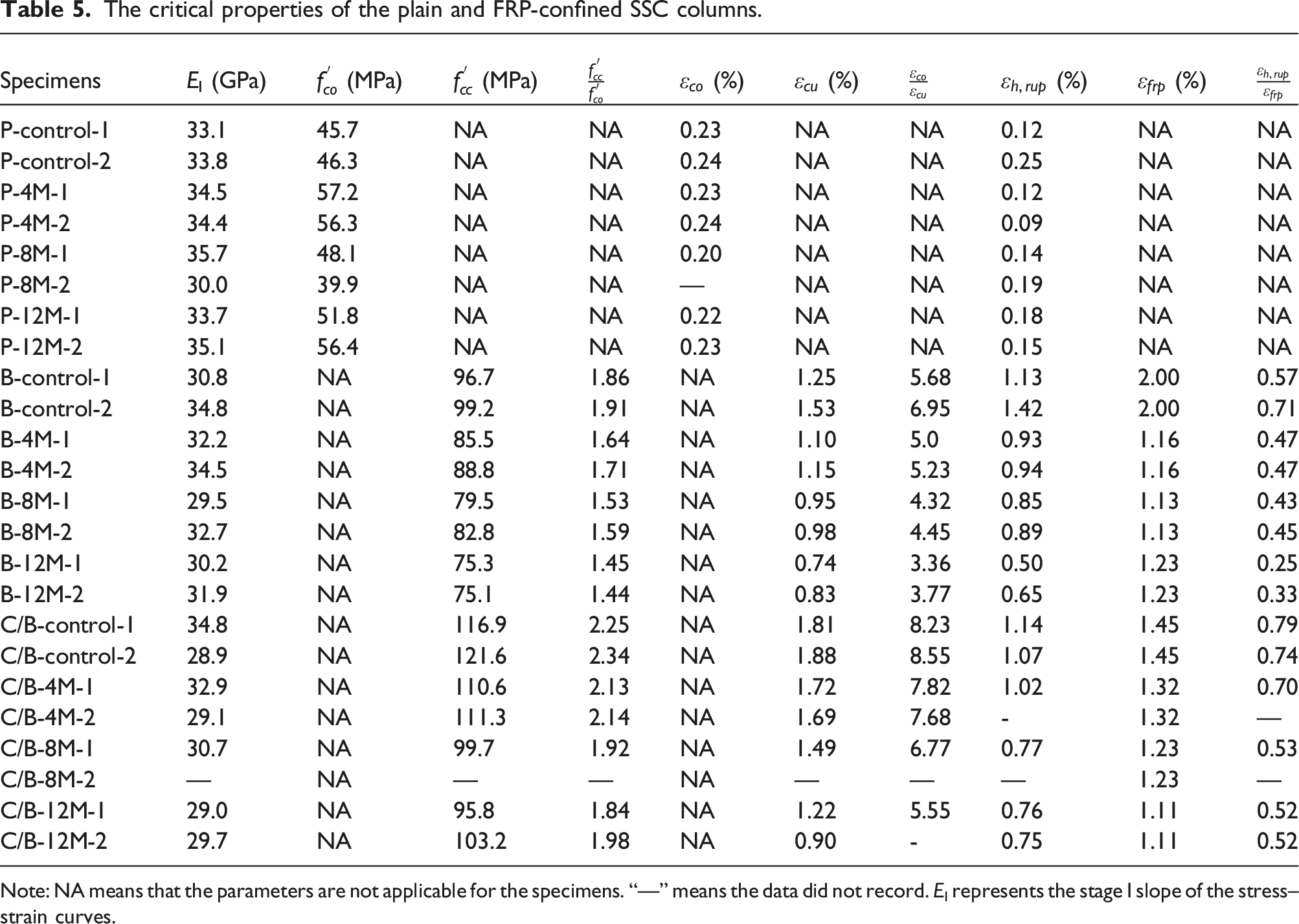
Note: NA means that the parameters are not applicable for the specimens. “—” means the data did not record. EI represents the stage I slope of the stress–strain curves.
Figure 5(b) and 5(c) depicts the strain hardening in stage III of BFRP-confined and hybrid C/BFRP-confined SSC columns. The slope of BFRP-confined and hybrid C/BFRP-confined SSC columns in stage III decreases with an increase in the immersion time. Compared to the BFRP-confined and hybrid C/BFRP-confined SSC columns, the plain seawater–sea sand concrete column shows strain softening in stage III (see Figure 5(a)). Cracks quickly propagate due to a lack of lateral pressure confining the expansion of the column. The critical properties of the stress–strain behavior include the ultimate strength (
Ultimate strength of columns
The ultimate strength (

The actual confinement ratio is defined as the ratio between The relationship between the strength enhancement ratio and the actual confinement ratio.
Equation (1) is adopted to fit the test results, and the exact formula is presented in Figure 6. Figure 6 demonstrates that the strength enhancement ratio of both BFRP-confined and hybrid C/BFRP-confined SSC columns linearly enlarges with an increase in the actual confinement ratio. A coefficient of determination of 0.99 and 0.97 (R2 = 0.99 and 0.97) indicates good agreement between the test results and equation (1). As presented in Table 5, the
As discussed above,
Figure 7 depicts the relationship between the strength enhancement ratio and immersion time. In the case of the control specimens, the strength enhancement of the hybrid C/BFRP-confined SSC column is more significant than that of the BFRP-confined SSC column. The hybrid C/BFRP improves the ultimate compressive strength of the FRP-confined SSC column, attributed to the higher stiffness of the hybrid C/BFRP sheet; the hybrid C/BFRP sheet also provides a more considerable hoop pressure than the BFRP sheet at the failure moment. In the case of the aged specimens, the strength enhancement ratio of the BFRP-confined SSC column decreases by 11%, 17%, and 23% after 4, 8, and 12 months of immersion in seawater respectively. In comparison, the strength enhancement ratio of the hybrid C/BFRP-confined SSC column drops by 7%, 16%, and 17% after 4, 8, and 12 months of immersion in seawater respectively, indicating that seawater immersion reduces the strength enhancement ratio of both BFRP-confined and hybrid C/BFRP-confined SSC columns. The strength enhancement ratio of the BFRP-confined SSC column declines more 40% than that of the hybrid C/BFRP-confined SSC column after 12 months of immersion. It is worth noting that the degradation rates of the strength enhancement ratio of the BFRP-confined and hybrid C/BFRP-confined SSC columns are similar. Equation (3) is proposed to model the relationship between the strength enhancement ratio and the immersion time as follows: The relationship between the strength enhancement ratio and the immersion period.



Ultimate strain of columns
The ultimate strain of the FRP-confined concrete (
Figure 8 shows the relationship between the strain enhancement ratio and The relationship between the strain enhancement ratio and 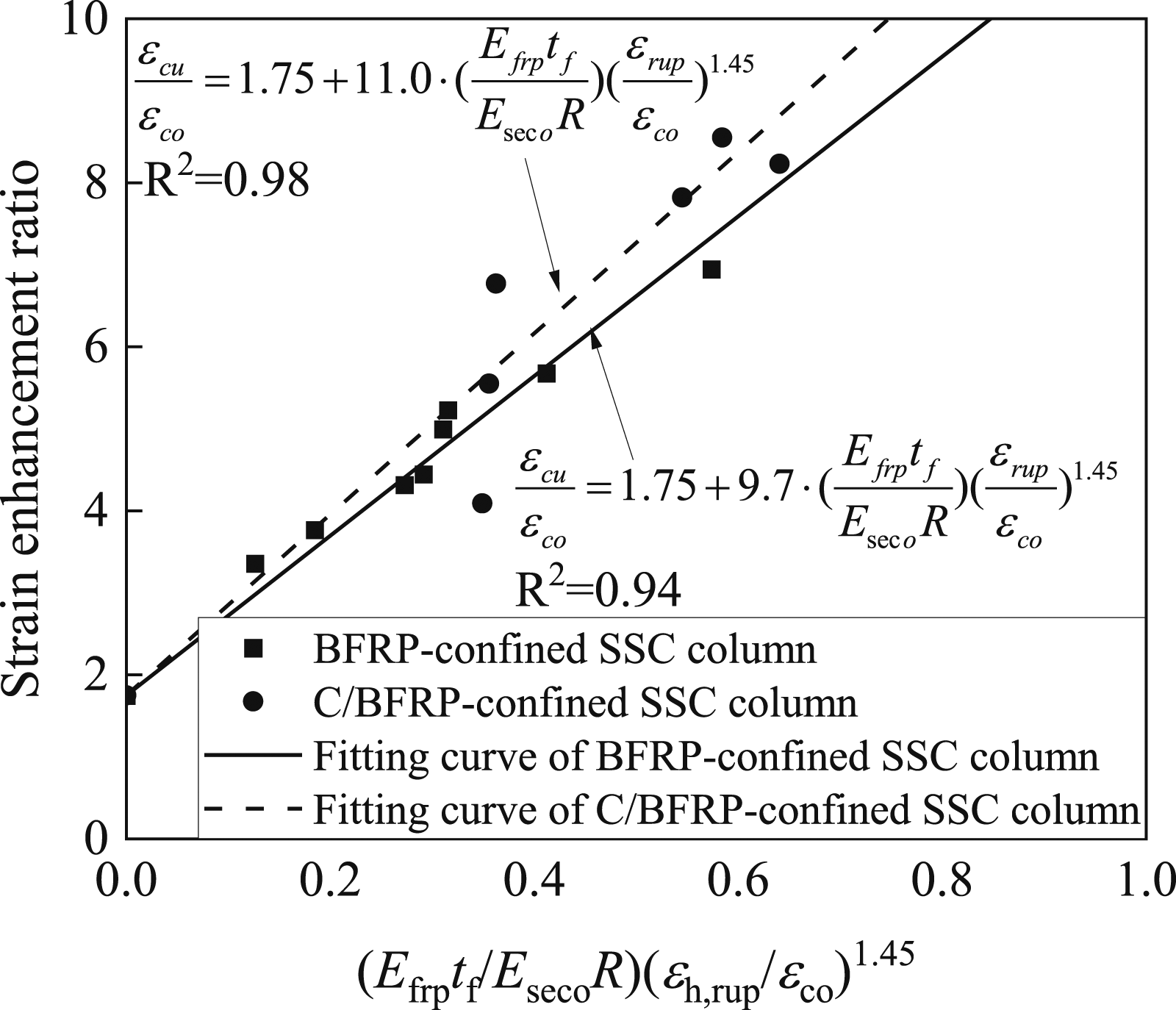
Figure 9 shows the relationship between the strain efficiency ratio and the actual confinement ratio. Figure 9(a) demonstrates that the nominal strain efficiency ratio of the BFRP-confined SSC column varies from 0.53 to 0.80, while that of the hybrid C/BFRP-confined SSC column ranges from 0.63 to 0.79. The nominal strain efficiency ratio of the hybrid C/BFRP-confined SSC column is better than that of the BFRP-confined SSC column. Figure 9(b) shows that the actual strain efficiency ratio rises with an increase in the actual confinement ratio for both BFRP-confined and hybrid C/BFRP-confined SSC columns, which is attributed to the reduction of The relationship of the (a) nominal strain efficiency ratio and (b) actual strain efficiency ratio with the actual confinement ratio.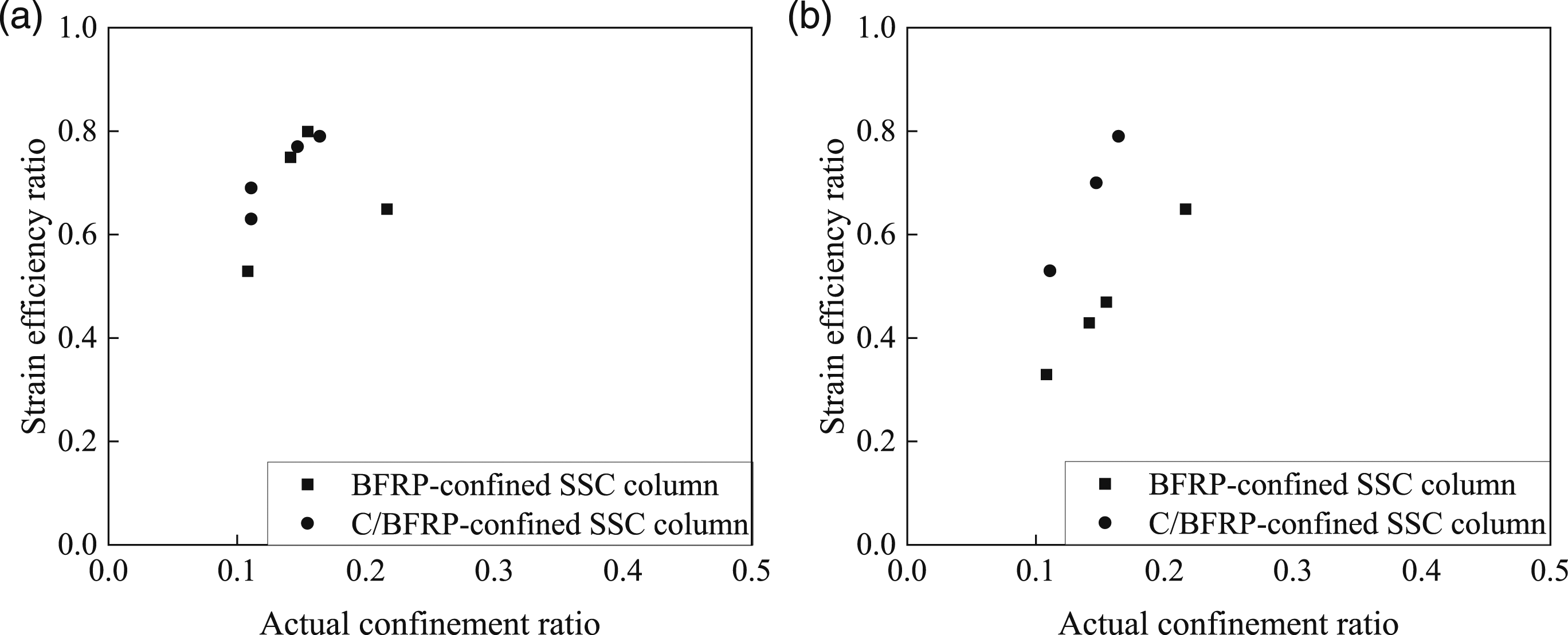
As discussed above, the strain enhancement ratio and The relationship between the strain enhancement ratio and the immersion period.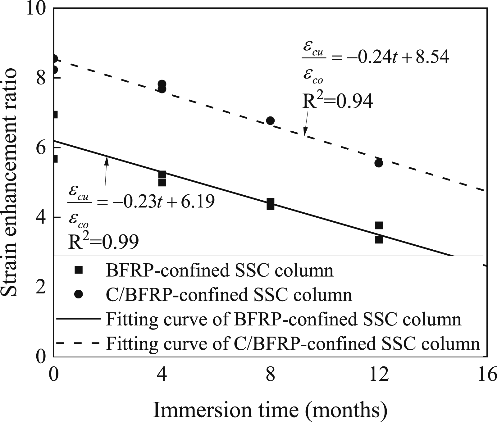
Equation (3) is adopted to consider the effect of the immersion period on the strain enhancement ratio. The strain enhancement ratio linearly decreases as the immersion time extends. The k
2
value of the hybrid C/BFRP-confined SSC column (–0.24) is similar to that of the BFRP-confined SSC column (–0.23), which indicates that the decrease in the strain enhancement ratio of the hybrid C/BFRP-confined SSC column is similar to that of the BFRP-confined SSC column. The evolution of the strain enhancement ratio can be expressed as a function of the immersion time as follows:

Dilation properties of columns
The lateral dilation of the FRP-confined SSC column results in the continuous deflection of the FRP sheet under axial compression. Figure 11 plots the relationship between the hoop strain and the axial strain for various columns. The hoop strain linearly increases with the axial strain in the initial stage for both plain and FRP-confined SSC columns, and the ratios between their axial and hoop strains are similar in the first stage. This indicates that the lateral pressure provided by the FRP jacket increases due to the dilation of the concrete under axial compression, and the dilation of the concrete is relatively slight owing to the linear elastic compressive stress–axial strain behavior. The rate of increase in the dilation of the concrete does not vary for different seawater immersion periods. The elastic modulus of the seawater–sea sand concrete controls the linear behavior in the first stage, and the effect of seawater immersion on the dilation of the concrete in the first stage is insignificant. The relationship between the hoop strain and the axial strain of the (a) plain SSC column, (b) BFRP-confined SSC column, and (c) hybrid C/BFRP-confined SSC column.
Figure 11(a) plots the hoop strain–axial strain response of the plain SSC column. The slope of the hoop strain–axial strain curve soars after cracks form in the concrete due to a lack of adequate confinement pressure.
Figure 11(b) delineates the hoop strain–axial strain relationship for the BFRP-confined SSC column. Compared to the plain SSC column, the hoop strain–axial strain curve of the BFRP-confined SSC column has two linear sections. Furthermore, compared to the first stage, the dilation rate of the concrete in the second stage increases with the SSC expansion, and the BFRP jacket confines the seawater–sea sand concrete core. The hoop strain of the aged specimens is smaller than that of the control specimens, attributed to the reduction in the elongation at break of the basalt-fiber-reinforced polymer sheet in seawater.
Figure 11(c) draws the relationship between the hoop strain and axial strain of the hybrid C/BFRP-confined SSC column. After the propagation of cracks in seawater–sea sand concrete, the significance of the confinement of the hybrid C/BFRP sheet increases due to the expansion of the seawater–sea sand concrete, and the increase in the dilation rate is higher in the second stage than in the first stage, attributed to the confinement provided by the hybrid C/BFRP sheet. The hoop strain of all the specimens reaches a similar value, followed by the rupture of the hybrid C/BFRP sheet. Moreover, the elongation at break of the hybrid C/BFRP sheet remains intact within 12 months of immersion in seawater. The hybrid C/BFRP-confined SSC column exhibits a higher increase in the dilation rate than the BFRP-confined SSC column, which is ascribed to the higher stiffness of the hybrid C/BFRP sheet than the BFRP sheet.
Stress–strain model of confined concrete considering effect of seawater immersion and fiber hybridization
A design-oriented model is adopted to predict the stress–strain behavior of FRP-confined concrete so as to determine its strength and ductility (Lam and Teng, 2003). The model comprises a parabolic curve and a straight line section and is expressed by the following:


Equation (12) defines 
Equations (2), (4), (7), and (8) calculate the ultimate strength and ultimate strain of the FRP-confined SSC columns, and the elastic modulus of the seawater–sea sand concrete is determined by Comparing the predicted results with the experimental data on the compressive stress–axial strain behavior of the seawater–sea sand concrete columns: (a) control BFRP-confined SSC column; (b) BFRP-confined SSC column immersed in seawater for 4 months; (c) BFRP-confined SSC column immersed in seawater for 8 months; (d) BFRP-confined SSC column immersed in seawater for 12 months; (e) control hybrid C/BFRP-confined SSC column; (f) hybrid C/BFRP-confined SSC column immersed in seawater for 4 months; (g) hybrid C/BFRP-confined SSC column immersed in seawater for 8 months; (h) hybrid C/BFRP-confined SSC column immersed in seawater for 12 months.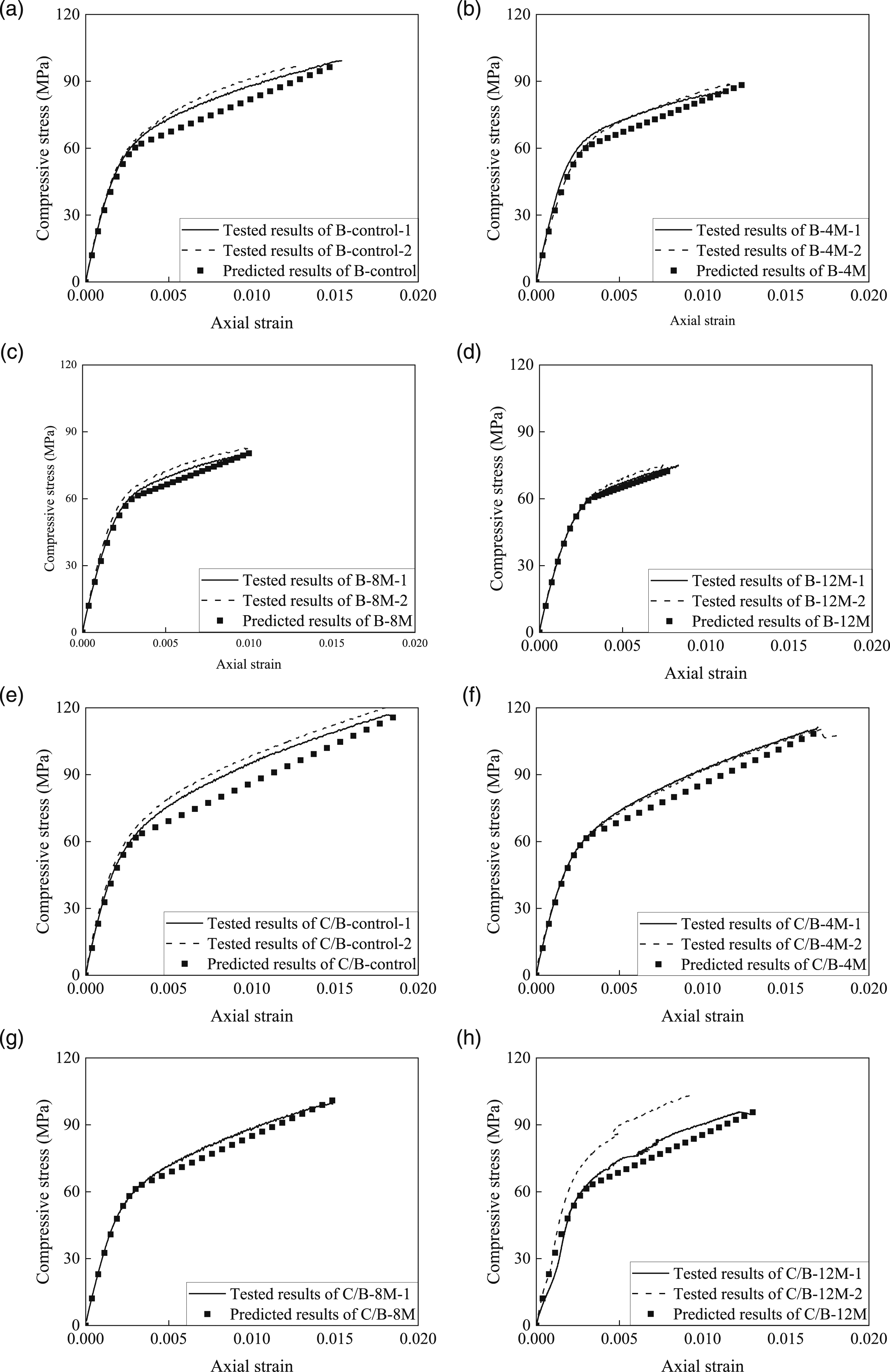
Conclusions
The present study examined the effect of a carbon–basalt hybrid sheet on the durability of the hybrid C/BFRP-confined SSC columns immersed in seawater and compared them with the BFRP-confined SSC columns. On the basis of the experimental results, a revised design-oriented model considering the effects of seawater immersion was proposed to predict the stress–strain behavior of the seawater–sea sand concrete columns. The following conclusions could be drawn from the experimental findings and the analytical results. • The hybrid C/BFRP sheet retained the tensile strength and elongation at break of the FRP-confined seawater–sea sand concrete columns immersed in seawater more than the BFRP sheet. Further, the effect of seawater immersion on the elastic modulus of both hybrid C/BFRP and BFRP sheets was insignificant. • The BFRP-confined SSC columns failed because of the rupture of the BFRP sheet, and their failure mode did not vary after being immersed in seawater. However, the failure mode of the hybrid C/BFRP-confined seawater–sea sand concrete columns was a combination of the delamination between the CFRP and BFRP sheets and the tensile failure of the hybrid C/BFRP sheet. The rupture of the hybrid C/BFRP sheet primarily happened after immersing the columns in seawater. • The degradation of the elongation at break of the BFRP and hybrid C/BFRP sheets resulted in the reduction of lateral pressure, decreasing the ultimate strength and ultimate strain of the columns immersed in seawater. The ultimate strength and ultimate strain of the BFRP-confined SSC columns deteriorated more severely than those of the hybrid C/BFRP-confined SSC columns. • Equations were proposed to predict the long-term ultimate strength and ultimate strain of both BFRP-confined and hybrid C/BFRP-confined SSC columns as a function of the immersion period, and the predicted stress–strain curves of the columns matched the test results.
Footnotes
Acknowledgements
The authors gratefully acknowledge the financial support provided by the National Natural Science Foundation of China [grant numbers 52078141, 52278280, and 51908507]; the Guangdong Basic and Applied Basic Research Foundation [grant number 2019A1515011431]; and the Zhejiang Provincial Natural Science Foundation [grant number LY19E080029].
Declaration of Conflicting Interests
The author(s) declared no potential conflicts of interest with respect to the research, authorship, and/or publication of this article.
Funding
The author(s) disclosed receipt of the following financial support for the research, authorship, and/or publication of this article: This work was supported by the National Natural Science Foundation of China [grant numbers 52078141, 52278280, and 51908507]; the Guangdong Basic and Applied Basic Research Foundation [grant number 2019A1515011431]; and the Zhejiang Provincial Natural Science Foundation [grant number LY19E080029].
