
Abstract
At present, the connection between the beams and slabs adopting composite layers is cast on-site, which is laborious and time-consuming. In this study, a new type of precast concrete (PC) beam and PC slab connection, which was connected by stud/channel steel connectors, was proposed to enhance the efficiency of prefabricated construction. Push-out tests were carried out on 5 PC beam-slab specimens connected with studs and 3 PC beam-slab specimens with channel steel connectors. The test variables were the connecting methods of beam-slab, the connector reinforcement ratio and the connecting width between two slabs. The failure process, load and slip of the beam-slab connection were recorded. Then, the slip behavior, shear capacity and shear stiffness of the PC beam-slab connection were analyzed. The results showed that the new type of PC beam-slab connection proposed in this study was an effective form for transferring force between the beam and slabs. Based on the push-out test results, the shear mechanism of connectors was analyzed and the calculation formulas for shear strength of stud/channel steel connectors were put forward. The calculated values obtained from the proposed formula demonstrated a strong correlation with the test results, providing an accurate measurement of shear strength of the new type of PC beam-slab connection. This study offers a reference for realizing the fast-full assembly construction of PC frame.
Introduction
Compared with the monolithic concrete frames, the precast concrete (PC) frame structure has the advantages of fast construction speed, short construction period, easy quality control and high economic benefits since components were made in factories in advance and then assembled on-site, having been developed and applied in many countries (Ahmed and Tsavdaridis, 2019; Pardeshi and Patil, 2021; Shariati et al., 2013; Viest, 1951). In addition, the PC frame structure can improve the reuse of components and reduce environmental pollution and energy consumption. The connection is critical in the PC frame structure (Restrepo et al., 1995; Savoia et al., 2017; Xu et al., 2019). However, the present connection method of composite beam and slab requires a large amount of post-placed reinforcements in the beams and slabs, and post-casting concrete in composite layers, which increases the workload of construction and restricts the development and application of PC frame structure to a certain extent (Kataoka et al., 2017; Meng et al., 2022). Therefore, proposing a new type of PC beam-slab connection with rapid assembly and superior performance is necessary.
Stud connectors are widely used to transmit longitudinal shear force at the interface between the steel/timber beam and concrete/timber slab due to their excellent performance and simple manufacturing process, guaranteeing adequate composite action between the two parts (Divya et al., 2023; Elif et al., 2021; Huo et al., 2018; Im et al., 2023; Nie and Valipour, 2021; Pathirana et al., 2015; Xu and Liu, 2019; Yang et al., 2022; Zhang and Xu, 2020). The typical steel-concrete composite beam with stud connectors is shown in Figure 1(a) (Liu et al., 2023). With the development of materials, a lot of research on the stud shear connectors of steel-concrete composite beams with the new type of concrete and high-strength steel was done. Tong et al. (2020) investigated the shear performance of high-strength steel beam and ultra-high-performance concrete (UHPC) slab. They conducted push-out tests on 6 specimens to analyze the influence of stud diameter and layout on the shear behavior of the composite system. All 6 specimens exhibited stud failure as the primary mode of failure. There were no discernible cracks on the UHPC slab’ s surface, and only UHPC at the root of the stud was broken. Wang et al. (2019) investigated the shear performance of 22 mm and 30 mm large-diameter studs anchored in UHPC through 18 push-out specimens. They proposed an empirical formula considering the diameter of studs according to the test results, and evaluated the existing formulas for calculating the shear strength of the studs. To sum up, extensive experimental research and theoretical analyses have been carried out on the stud shear connectors in steel-concrete composite beams, investigating the impact of factors such as stud diameter, anchorage depth of studs in the concrete slab, and concrete type on the performance of stud connection. Their results showed that stud connectors exhibited excellent shear performance. Typical steel-concrete composite beam with: (a) stud connectors (Liu et al., 2023); and (b) channel steel connectors (Arikoglu et al., 2020).
Channel steel is also used in the connection of composite beams to resist the shear force caused by the dislocation of the steel beam and concrete slab interface, and scholars have conducted a lot of experimental and theoretical research on the steel-concrete composite beams (Arikoglu et al., 2020; Baran and Topkaya, 2012, 2014; Hosain and Pashan, 2006; Paknahad et al., 2018). The typical steel-concrete composite beam with channel steel connectors is shown in Figure 1(b) (Arikoglu et al., 2020). Paknahad et al. (2018) conducted push-out tests on 8 specimens with different sizes of channel steel connectors to analyze the influence of high strength concrete on the shear bearing capacity of channel steel connectors in the steel-concrete composite system. The results showed that all the specimens had fracture of channel steel connectors and had good ductility. Pashan and Hosain (2009) conducted an experimental study on channel steel connections with different types of slabs. For solid slab specimens, the failure was mainly caused by the fracture of channel steel web at the root or the splitting of concrete, while for the metal slab specimens, the failure of concrete shear plane occurred. It could be concluded that the bearing capacity of solid slab specimens was higher than that of the metal slab specimens. The previous studies mentioned above mainly focused on the performance of channel steel connectors in steel-concrete composite beams, which exhibited excellent shear performance.
In addition to the above research on the shear connections in steel-concrete composite beams, Jiang et al. (2021) studied the shear capacity of the precast UHPC beam-concrete slab connection. Besides, for the research on the seismic performance of the joint, Wang et al. (2020) proposed a new beam-to-column joint with reinforced concrete slab, which were connected to the beam by U-shaped connectors. Meanwhile, Qing et al. (2023) developed a new PC joint, in which the slab and beam were superimposed by post-casting concrete. At present, the research on PC beam and slab mainly considered the influence of the PC slab on the seismic performance of the joints and the research on push-out performance of shear connector in the PC beam-slab connections are limited.
It was apparent that the steel-concrete composite beams and concrete slabs with stud/channel steel connectors were easy to construct, showing their excellent mechanical properties. Nevertheless, constructing the PC beam and slabs on-site is difficult due to the large number of reinforcements and cast-in-place concrete needed in composite layer. Therefore, it is attractive to use a manner similar to steel-concrete composite beams to connect PC beam and slabs. Meanwhile, the applicability of stud/channel steel connecting form in PC beam and slabs connection was limited. Hence, to achieve better performance and easier construction of PC frames, the reasonable stud/channel steel form to connect the PC beam and slabs should be further explored, and the shear mechanism and the corresponding design method by combining the test and theoretical analysis needed to study. Additionally, further research on stud/channel steel connectors in UHPC should be conducted since UHPC can effectively inhibit the generation and development of cracks in composite beams.
This study proposed a new type of PC beam-slab connected by studs or channel steel connectors for easy and efficient construction as well as the excellent composite effect in between. The main purpose of this study was to examine static performance of the proposed PC beam-slab connection by push-out tests, and develop design considerations of studs and channel steel connectors embedded in UHPC for PC beam-slab connection. The failure mode, load-slip curve and shear bearing capacity of PC beam-slab connection were analyzed, and the influence of the connecting method, connector reinforcement ratio and the slab type on the shear behavior were evaluated. Finally, new equations for calculating the shear strength of the PC beam-slab connection connected by this new connecting method were put forward. These findings were expected to provide a design reference for the dismountable and economical beam-slab connection in PC frame structures.
Developed PC beam-slab connection
As shown in Figure 2, a new type of PC beam-slab connection was proposed to improve the rapid construction and performance of PC frame structures, including PC beams with embedded shear connectors, PC slabs and split-joint areas. The shear connectors including studs and channel steels partially embedded in the PC beam can better transmit the shear forces at the interface between the beam and slabs. When using this connecting method in the PC frames, the PC beams and slabs can be fabricated in a factory, respectively, and then fabricated on-site. There would not be post-placed reinforcements of beam and slab and post-casting concrete in composite layers, and there is no need for temporary templates. Newly developed beam-slab connection.
The process of connection is as follows: the PC beams and slabs were fabricated in a factory and the connectors were embedded in the PC beams. Then, the PC beams and slabs were assembled on-site. The PC slabs were overlapped on the PC beam, and then connecting reinforcements were placed at the split-joint area. Finally, the concrete was poured in the split-joint area at the horizontal position to ensure a good composite effect of the beam and slab.
Experimental programs
Design and description of specimens
Test parameters of the beam-slab specimen.

Note: Ns = number of stud/channel steel connectors; Rs = connector reinforcement ratio (ratio of the connector area to the interface area of the beam and slab); CW = connecting width between two slabs (mm).
SRBS1 and SRBS3 were equipped with two studs on each side resulting in a 0.3% connector reinforcement ratio, and SCBS and SHBS were equipped with three studs on each side (0.45% connector reinforcement ratio), all of which were 140 mm in height and 16 mm in diameter. SRBS2 was equipped with four studs on each side with a height of 140 mm and a diameter of 13 mm (0.45% connector reinforcement ratio). Two kinds of split-joint widths, 50 mm and 100 mm, were considered to compare and analyze the influence of different split-joint widths on the shear performance of PC beam-slab connections. Specimens CRBS, CCBS and CHBS were embedded with one channel steel connector of 100 mm × 48 mm × 5.3 mm on each side of the PC beam resulting in a 0.4% connector reinforcement ratio. To strengthen the channel steel web at the connection interface of the PC beam and slabs, a 40 mm × 25 mm × 4 mm unequal limb angle steel with a length of 100 mm was welded to the channel steel web at the connection section. The embedded height of all studs and channel steel connectors was half of their total height, respectively.
The sizes and reinforcement arrangements of all specimens are shown in Figure 3. Each specimen was composed of 4 PC slabs and 1 PC beam. To improve the integrity of the connection between the beam and slab, a shear groove with a width of 50 mm was reserved at the end of the precast slab, so that the post-casting concrete could have a better bite with the precast concrete. The section size of the PC beam was 300 mm × 300 mm, the height was 500 mm, the size of the PC slab was 200 mm × 500 mm, and the thickness was 120 mm. The bottom thickness of the ribbed composite slab was 40 mm, the height and width of the rib were 50 mm and 200 mm, respectively. The hole diameter of the hollow slab was 50 mm, and the spacing of the holes was 75 mm. PC slabs and beams were all cast with C40 concrete. 8 steel bars of 630 MPa with a diameter of 22 mm were placed in the PC beam as longitudinal reinforcement bars, while steel bars of 630 MPa with a diameter of 6 mm and 100 mm spacing were used for the stirrup. To prevent premature damage of the beam end during loading which would adversely affect the test results, 8 additional steel bars of 630 MPa with a diameter of 22 mm were configured at the loading end of the beam, and the spacing of transverse bar was shortened to 50 mm. The PC slab was equipped with a two-layer steel mesh formed by 630 MPa steel bars with a diameter of 8 mm. The transverse and longitudinal spacing of the steel bars were 150 mm and 170 mm, respectively. The diameter and strength of the connecting reinforcements were same as those in the slabs. The type of split-joint post-casting concrete was UHPC. Sizes and reinforcement arrangements of the specimens: (a) side view of SRBS1 and SRBS3; (b) side view of SCBS and SHBS; (c) side view of SRBS2; (d) front view of SRBS1, SRBS2 and SRBS3; (e) front view of SCBS; (f) front view of SHBS; (g) side view of CRBS, CCBS, CHBS and size detail of their connectors; (h) front view of CRBS; (i) front view of CCBS; and (j) front view of CHBS; and (k) three-dimensional diagram of SHBS.
Fabrication of specimens
The fabrication process of PC beam-slab connection was shown in Figure 4 (taking SRBS1 as an example). Firstly, the PC beam with pre-embedded studs and slabs were prefabricated separately in a factory. Secondly, the prefabricated PC beam and slab were transported on-site. The PC slabs were lapped to the edge of PC beam, and then the connecting reinforcements were placed to connect the PC beam and slabs. Finally, UHPC was poured into the split-joint area. Fabrication process of the developed beam-slab connection.
Material mechanical properties
Mix proportions of UHPC (unit is kg/m3).


UHPC components: (a) cement; (b) silica fume; (c) powder; (d) quartz sand; (e) superplasticizer; and (f) steel fiber.
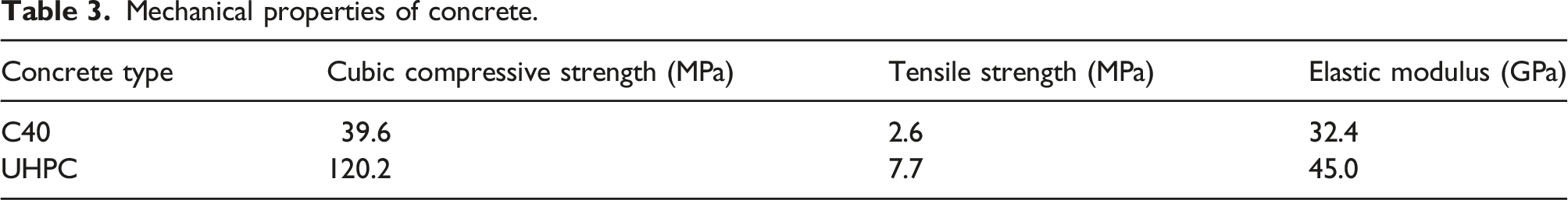
Mechanical properties of concrete.
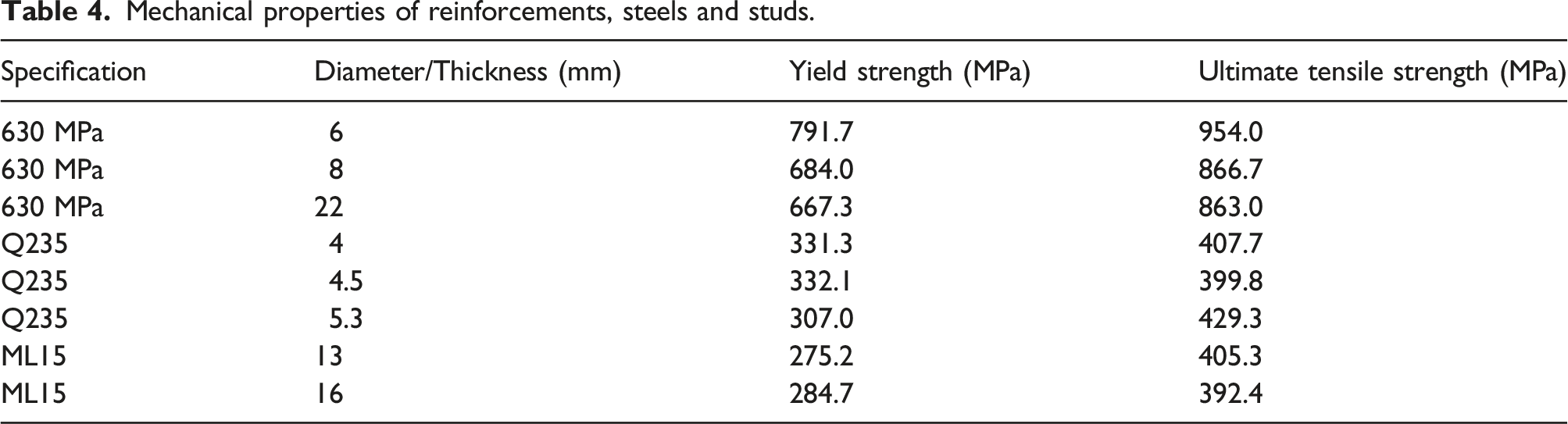
Mechanical properties of reinforcements, steels and studs.
Experimental loading design and measurements
As shown in Figure 6, the push-out specimens were tested in a micro-controlled electro-hydraulic servo pressure testing machine with a loading capacity of 2000 t. According to European Specification EC4 (EN 1994-1-1: 2004, 2004), the concrete slab was placed on a rigid platform without any horizontal constraints on the specimen to reflect the actual constraints of the connection between the beam and slabs. A steel plate was placed between the loading plate and the top of the specimen to ensure a uniform load application and prevent local concrete breakage at the top of the concrete beam section during loading. The new type of PC beam-slab connection specimen was subjected to vertical force, which simulated shear force between the beam and slab. Diagram and photo of the test setup.
Figure 7 shows the loading procedure adopted in the test, which could be divided into two stages according to EC4 (EN 1994-1-1: 2004, 2004): the force-controlled stage and the displacement-controlled stage. In the first stage, each specimen was firstly loaded to 0.4 Pu,e at a loading rate of 5 kN/s and then reduced the load to 0.05 Pu,e, where Pu,e represented the estimated ultimate load. Based on EC4 (EN 1994-1-1: 2004, 2004), the load was repeated 25 times between 0.05 Pu,e and 0.4 Pu,e for examining the service performance of the connector and reducing the effect of friction between the PC beam and slab. In the second stage, the loading time of each specimen was not less than 30 min at the loading rate of 0.5 mm/min. Finally, the test loading terminated when the load was reduced to 0.8Pu, where Pu represented the ultimate load during the test loading. Loading procedure.
As shown in Figure 8, the displacement transducers D1 and D2 were set between the PC beam and slab to measure the relative slippage of the beam, the displacement transducers D3 were set in the middle of the PC beam to measure the vertical displacement of the beam, and the lateral displacement transducers D4 and D5 were set on the sides of the two slabs to measure the lateral displacement of the beam. In addition, strain gauges S1-S2 and P1-P4 were arranged on the connecting reinforcements and shear connectors to measure their strains. After the specimen was placed on the testing machine, the displacement gauges and the wire of the strain gauge was connected to the strain collection box for obtaining measurement during loading. Arrangements of displacement transducers and strain gauges: (a) arrangements of displacement transducers; (b) arrangements of strain gauges in the studs; (c) arrangements of strain gauges in the channel steel connectors; and (d) arrangements of strain gauges in the connecting reinforcements.
Experimental results and discussions
Experimental phenomena and failure mode
During the 25 cyclic loading periods of force-controlled, there was no obvious phenomenon in all the PC beam-slab connection specimens. The relative slippage of the beam and slabs was small and the shear force was jointly borne by the friction force, the adhesion force and the shear connector of the interface in between. During the displacement-controlled stage, the relative slippage of the beam-slab interface gradually increased, the contribution of friction force and adhesion force to shear force gradually decreased, and the studs and channel steel connectors mainly bore shear force until the specimen failed.
The crack distributions and failure modes of all specimens are shown in Figure 9. All specimens with stud connectors presented a composite failure phenomenon including studs’ fracture and the crushing of concrete around the studs. At the initial stage of the displacement-controlled stage, there were no cracks on the PC slab due to the post-casting UHPC in the split-joint area with higher cracking resistance, and no obvious separation occurred due to the small slippage between the PC beam and slabs. Thus, there was no obvious damage of the concrete around the studs. As the loading continued, a slight separation between the PC beam and slabs was observed, which was attributed to the large deformation of studs under the local compressive force. For the specimens with more than two stud connectors like specimens SRBS2, SCBS and SHBS, one stud exhibited incomplete fracture while displaying significant bending deformation in the PC beam. For specimen SHBS, cracks appeared in the corner of the slab due to the use of PC hollow slab. Typical failure modes and crack patterns: (a) overall failure modes of specimens with studs (taking SRBS1 as an example); (b) studs fracture (taking SRBS2 as an example); (c) cracks patterns (taking SHBS and SRBS3 as examples); (d) overall failure modes of specimens with channel steel connectors; (e) cracks patterns at the corner of CCBS and CRBS’s PC beams; and (f) channel steel connector fracture (taking CCBS as an example).
By observing the section of the failed specimens, the deformation of the studs embedded in PC beams was larger than that of in the split-joint area, and the crushing range of concrete around the studs on the side of the PC beam was larger than that of the PC slabs due to UHPC with higher strength, which was different from the phenomenon in steel-concrete composite beams (Tong et al., 2020). A cavity was also observed behind the studs due to the local deformation of the studs. Moreover, it can be found that stud fracture occurred around the stud root due to the largest shear stress. The large compressive and shear stresses resulted in cracks near the stud root (Lebet et al., 2006). The uplift area in the middle of the studs resulted from shear deformation of the studs and prying-out effect exerted by concrete. In the pulled area above the studs, there was enough anchorage to prevent the studs from being pulled out, and the appropriate thickness of the protective concrete layer to prevent the splitting of the PC slab (Fang et al., 2023). Meanwhile, it can be expected that using double-headed studs will ensure that this anchorage is more reliable enough to resist being pulled out.
Similar to the specimens with stud connectors, there were no cracks on the PC slab of specimens CRBS, CCBS and CHBS with the channel steel connectors due to the post-casting UHPC in the split-joint area, and slight separation occurred due to the large slippage between the PC beam and slabs at the initial loading of the displacement-controlled stage. As loading continued, two inclined cracks appeared in the lower corner of the PC beam of specimen CCBS. Then the relative slip of the PC beam and slab increased rapidly, and when the specimen reached the ultimate load, the steel connector fractured, resulting in the obvious separation between the PC beam and slab. The same findings were observed in steel-concrete composite beams (Arikoglu et al., 2020; Fang et al., 2023). By observing the section of the specimen after separation to investigate the performance of channel steel connectors, the scope of concrete crushing on the surface of the PC beam was large, while there was no obvious concrete splitting crack on the surface of PC slabs, which was different from the steel-concrete composite beams (Wang et al., 2019).
Three different failure modes were usually found in previous push-out tests on steel-concrete composite beams, which included concrete failure, connector failure, and combination failure of the connector and concrete slab (Lam and EI-Loboddy, 2005; Qi et al., 2017; Xue et al., 2012). In this study, the fracture of the connector mainly occurred. Besides, the concrete deformation occurred at the split-joint interface in the steel-concrete composite beams, while in this study, it occurred in the PC beams due to the higher compressive strength of UHPC in the split-joint. The deformation of the stud connectors was mainly concentrated near the interface between the beam and split-joint due to the shear force and bending moment brought by the separation of beam and slab, while the deformation of the channel steel connectors was mainly concentrated at the channel steel web in the beam. In addition, compared with studs, the concrete crushing of specimens using channel steels as connectors were larger because the channel steel web compression area was relatively large.
Load-slip curve
Figure 10(a) shows the representative load-relative slip curves under the cyclic loading (taking SRBS3 as an example). During the first cycle loading period of 25 cycles controlled by load, the slippage of the beam-slab connection interface increased rapidly as loading, then increased stably, and the residual slippage appeared on the beam-slab connection interface after unloading. The maximum residual slippage of SRBS3 with stud connectors was 2.65 mm, while that of CCBS with channel steel connector was 1.40 mm, resulting from the large shear stiffness provided by the channel steel connector. Load-slip curves: (a) load-relative slip curves of SRBS3under the cyclic loading (b) specimens with stud connectors and (c) specimens with channel steel connectors.
Figure 10(b) and (c) illustrate the load-slip curves of PC beams and slabs with stud and channel steel connectors, respectively. These curves served as crucial indicators in push-out experiments, which had a significant role in analyzing the interface slip and bearing capacity of PC beam-slabs. All specimens had a similar development trend in load-slip curves, which could be divided into four phases including the elastic phase, the elastic-plastic phase, the plastic phase, and the failure phase. At the elastic phase, the relationship between the load and its corresponding slippage was approximately linear. As the slippage continued to increase, cracks occurred at the interface between the beam and slabs, and the curves showed nonlinearity, entering the elastic-plastic phase. The curves tended to ascend and the stiffness decreased due to the nonlinear behavior of the material, which indicated the arrival of the plastic phase. Specimens SRBS2, SCBS and SHBS entered the plastic phase later than other specimens with studs due to their high connector reinforcement ratio, while SRBS2 had lower load values due to the effect of multiple connectors. Then, an obvious plastic strengthening stage appeared for the PC beam-slab connected by studs, which was mainly caused by the deformation of the studs and the formation of a cavity due to the concrete damage around the studs. For specimens with stud connectors, the load-slip curves decreased rapidly after the load reached its peak except for the specimen SCBS with composite slabs, but there was still residual load which was mainly borne by unbroken studs.
For specimens with channel steel connectors, CCBS entered the plastic phase a little earlier than CRBS and CHBS, possibly because the slab used in specimen CCBS had composite layers leading to the separation of the beam and slabs. Then, the channel steel occurred deformation, causing constraint on the concrete around the channel steel connectors. Meanwhile, the angle steel limited this deformation of the channel steel, indicating that specimens with channel steel connectors entered the plastic strengthening stage when the slippage was about 15 mm, 15 mm and 20 mm for specimens CRBS, CCBS and CHBS, respectively. When the load reached its shear capacity, the sudden drop of the curves appeared, the fracture of the channel steel web occurred and the specimens entered the failure phase. At this stage, the load and slippage were different due to the different types of PC slabs used in the three specimens.
The load-slip curves of PC beam-slab connection with post-casting UHPC in split-joint in this study were different from that of the traditional steel-concrete composite beam (Tong et al., 2020). The slope of the load-slip curve of the steel-concrete composite beam was larger than that of the PC beam-slab connection in this study, indicating that the stiffness of the former was larger. This is mainly because the connector was welded on the steel beam in the steel-concrete composite beam with a strong constraint effect, while the studs were embedded in the PC beam and the split-joint area, and deformation occurred in both. Additionally, the slip of the PC beam-slab connection was larger than that of the steel-concrete composite beam since the concrete was crushed in the PC beam and a cavity occurred in the UHPC on the side of the PC slab, while only the damage of the PC slab was found in steel-concrete composite beam. There was no obvious phenomenon on the steel beam side. Furthermore, the failure of the steel-concrete composite beam and PC beam-slab connection was both dominated by the stud fracture when reaching the ultimate bearing capacity.
Slip capacity
Summary of experimental results.
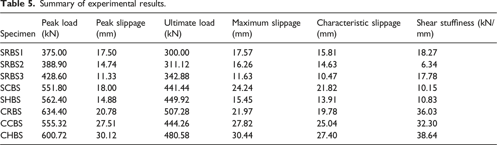
Generally, the channel steel connectors exhibited larger slip deformability than the stud connector for specimens with similar connector reinforcement ratios due to the former having a strong confinement effect on concrete and withstanding great plastic deformation before fracture. The characteristic slippage of CRBS, CCBS and CHBS was 19.78 mm, 25.04 mm and 27.40 mm, respectively, indicating the specimen with hollow slabs possessed the largest slip followed by that with ribbed composite slabs, and the specimen with rectangle slabs had the smallest slip performance. A different conclusion was achieved for specimens with the stud connectors (SCBS and SHBS). These results indicated that the type of PC slab had an obvious influence on the slip ability of the PC beam-slab connection. For specimens with studs (SRBS1 and SRBS3), a greater connecting width between two slabs led to a higher slip deformability. In contrast, the stud number showed an obvious effect on the slip behavior at the failure stage, and the slip continuously increased for specimens with four studs withstanding the load.
The connectors embedded in the PC beam-slab exhibited obvious flexural deformation and could be regarded as a kind of flexible shear connectors, which resulted in the larger slip performance. This set them apart from traditional steel-concrete composite beams with studs or channel steel connectors. Meanwhile, the minimum characteristic slippage of specimens designed in this study was 10.47 mm, much larger than 6 mm, which met the high slip-deformability requirement of EC4 (EN 1994-1-1: 2004, 2004) and showed the ductility characteristics of this PC beam-slab connection. This phenomenon could be verified in section Experiemental phenomena and failure modes showing concrete crushing was prior to the connector fracture.
Shear capacity
The shear capacity of beam-slab connections is another significant index to directly reflect the advantages and disadvantages of its mechanical performance. Usually, the peak load mentioned above is taken as the shear capacity of the beam-slab connection.
The shear capacity of SCBS with composite slabs and SHBS with hollow slabs was similar, showing that the type of PC slab had little impact on shear capacity of the beam-slab with stud connectors. However, by comparing the ultimate load values of specimens with channel steel connectors, it was found that the ultimate load of CRBS with rectangular slabs was 14.2% and 5.6% higher than that of CCBS with composite slabs and CHBS with hollow slabs, respectively, indicating that rectangular slab exhibited the highest shear capacity. Compared with the studs, the channel steel connectors had higher shear capacity, although the connector reinforcement ratio of channel steel was slightly lower than that of the studs. The main reason was that the channel steel connector had a strong constraint effect on concrete, and the stiffness of channel steel connector was larger than that of stud, resulting in the former having larger shear capacity in the PC beam-slab connection.
As seen in Table 5, the ultimate load of SRBS2 was smaller than that of SCBS and SHBS due to the stud arrangement adopted by SRBS2, which resulted in a small transverse spacing of studs called multiple connectors effect leading to a decrease in shear capacity of beam-slab connection, although they had the same connector reinforcement ratio. Additionally, SRBS3 exhibited 14.3% higher shear capacity than specimen SRBS1, indicating the former with smaller connecting width between two slabs had greater shear capacity.
Shear stiffness
The secant stiffness, obtained by drawing a secant line on the load-slip curve, is commonly used to represent the shear stiffness under a particular load. This parameter reflects the connection interface’s resistance to slip, which ultimately impacts the flexural deformation capacity of specimens. Therefore, it is necessary to analyze the shear stiffness of the new type of PC beam-slab connection.
In this study, the shear stuffiness of the stud/channel steel connectors was calculated by European code EC4 (EN 1994-1-1: 2004, 2004) (equation (1)), and the calculation results are shown in Table 5.
As shown in Table 5, the shear stiffness of SRBS2 was the smallest due to the increase in the length-diameter ratio of studs in the PC beam-slab connection. The shear stiffness for SRBS1 and SRBS3 both with 16 mm diameter studs were 2.88 times and 2.8 times that of SRBS2 with 13 mm diameter ones due to the slight bending deformation of large diameter studs, respectively. Thus, the specimen with large-diameter studs had higher shear stiffness. In addition, the shear stiffness of SHBS was 6.7% larger than that of SCBS, indicating that the type of slab had a slight influence on the shear stiffness of the PC beam-slab connection. Similarly, for the PC beam-slab specimens with channel steel connectors, the shear stiffness of different types of slabs had little difference when the connector reinforcement ratio was same. Furthermore, it could be found that the shear stiffness of channel steel connectors was much larger than that of stud connectors, resulting from the larger shear section area of channel steel.
Strain analysis
As shown in Figure 11, during the initial loading, the strain of each steel connector increased almost linearly, and the increase speed was slow. As the loading continued, the strains significantly increased with non-linear characteristics due to the large shear deformation of the steel connectors. Under the same loading level, the strain of the steel connector’s part embedded in the PC beam was greater than that embedded in the PC slab. This was mainly because UHPC in the split-joint of the slab had a constraint effect on the connector’s deformation. The steel connector’s part embedded in the PC beam occurred uplift area due to the concrete prying out. In the later stage, the strain difference between the two parts was more obvious because the deformation of the connector caused the separation between the PC beam and slab. Moreover, the strain of connecting reinforcements were less than 1500 με, indicating that the reinforcements were in elastic state. Strain of steel components.
Theoretical calculations on shear strength of connectors
Connectors deformation
Figure 12 shows the failure mechanism of studs. It could be seen that the studs of all specimens bore shear force from the PC beam and counter-acting force from the UHPC in the split-joint area with and occurred plastic deformation. The strength of the concrete in the PC beam was small, and the restraint by concrete around the studs became weaker due to the damage of the concrete. Under the continuous loading, UHPC in split-joint area was pried out and the studs were separated outward along the cracks near the beam-slab interface, resulting in the uplift area in the middle of the studs. Before the slip of the beam-slab interface, the external force of studs embedded in PC beams was perpendicular to the studs, and after the slip, the studs were deflected and not pulled out due to the enough embedded depth of stud in PC beam. Then the external force could be decomposed into one parallel to the studs and one perpendicular to the studs. Thus, the studs were in complex stress states of tension, shear and bending moment. Because of the disappearance of the interaction between studs and concrete, the ability to transfer shear force was weakened, and the studs occurred plastic deformation but were not broken. On the contrary, UHPC in the split-joint area exerted a strong constraint on studs. As a result, the studs were also in a complex stress state. The studs were fractured when it reached its ultimate strength, and the shear capacity of the beam-slab connection was controlled by the studs’ shear capacity. Failure mechanism of studs.
The ultimate slip Smax can be determined by equation (2) after the failure of the specimen,
Figure 13 shows the failure mechanism of channel steel connectors. The failure was mainly related to the fracture of the channel steel connector near the fillet between the web and flange. Due to the large elastic modulus and high strength of UHPC, the deformation of the channel steel connector in the split-joint area was limited. However, the channel steel connector anchored in the PC beam mainly relied on the web of the connector with weak stiffness to bear pressure, leading to its deformation being larger than that in the split-joint area. When loading, the concrete on the upper surface of the web anchoring to the PC beam also occurred large deformation under the local pressure, which could be regarded as the co-deformation of the web and concrete. The lower surface of the web anchoring to the PC beam generated large bending stress near the beam-slab interface under the mutual dislocation, resulting in a trend toward separation of the PC beam and slab. At the same time, the connector would hinder this separation, so that the web bore tensile stress. Failure mechanism of channel steel connectors.
Calculation method for shear strength of specimens with stud connectors
This section evaluated the shear strength of the newly developed beam-slab connection based on the formulas in various nations applied for the steel-concrete composite beams.
The calculation formula for the shear strength of stud connectors according to American AASHOT-LRFD (2012) regulation is shown in equation (3).
Chinese code (GB 50017-2017) (2017) stipulates the shear strength of stud connectors calculated by equation (4).
In another Chinese code (GB 50917-2013 (2013)), the shear strength of stud connectors is defined as equation (5).
The European code EC4 (EN 1994-1-1: 2004, 2004) mentions the calculation formula of the shear strength of stud connectors as shown in equation (6).
Comparison of the stud shear strength between experimental and calculated results.

Note: Nvt is the experimental results (kN); Nvc1, Nvc2, Nvc3 and Nvc4 are the shear strength calculated according to AASHTO-LRFD, GB 50017-2017, GB 50917-2013 and EC4, respectively (kN); Nvcp is the calculated values of the proposed equation (kN); and AVG, SD, CV are average, the standard deviation and the coefficient of variation for the ratio of predicted and experimental results, respectively.
Considering the above situation, for the new type of PC beam-slab connection with studs, the slip of the studs in UHPC was small. Thus, the ratio of compressive strength between UHPC and normal concrete was introduced as the influence coefficients of UHPC to show the effect of post-casting UHPC on the enhancement of shear capacity. Equation (7) is obtained by optimizing the concrete item in the equation proposed by AASHOT-LRFD (2012).
In addition to the concrete’s shear contribution mentioned above, the studs’ shear contribution also needed to be taken into account. Equation (8) not only considered the influence of the cross-sectional area of stud, A
s
, on shear strength, but also considered the same stud configuration reduction coefficient, λ, as Fang et al. (2022) to improve the applicability of the proposed formula. λ was 1.15 for the single-row stud, 0.85 for four-row stud spacing less than 2.7 times of stud diameter, and 0.8 for dense stud arrangement.
Therefore, considering the feasibility of the equation, the shear strength of the push-out specimens in this study could be calculated according to equation (9) by taking the smaller value.
By comparing experimental results with calculated values obtained from proposed formula in Table 6, it could be seen that the ratio of the calculated values to the experimental results fell between 0.9 and 1.0. In addition, the mean value of the ratio was 0.97, indicating that the calculated values were in good agreement with the experimental results and the formula proposed in this study was more accurate than the existing national standard. This benefited from the improvement of the concrete’ shear contribution item and the concrete’ shear contribution item in equation (7).
Calculation method for shear strength of specimens with channel steel connectors
In this section, the shear strength of the new type of beam-slab connection in this study was calculated based on shear strength formulas in the existing design specifications ANSI/AISC 360–16, 2016 (equation (10)) (2016), CAN/CSA-S16 (equation (11)) (2001), GB 50017-2017 (equation (12)) (2017).


In addition to the above empirical equations (Equations (10)–(12)) which considered the effects of flange thickness, web thickness and channel steel connectors’ length on the shear strength under the constraint of channel steel connectors, the simplified equations (Equation (13)) for the shear strength of steel-concrete composite beams proposed by Pashan and Hosain, 2009 had taken into account the embedment length of channel steel connectors. Meanwhile, the equations (Equation (14)) proposed by Baran and Topkaya, 2012 introduced the combination coefficient f1×f2 (equations (15) and (16)) determined by the embedment length and length of channel steel connectors as a consideration for the constraint effect of the channel steel connectors.


Comparison of the channel steel shear strength between experimental and calculated results.
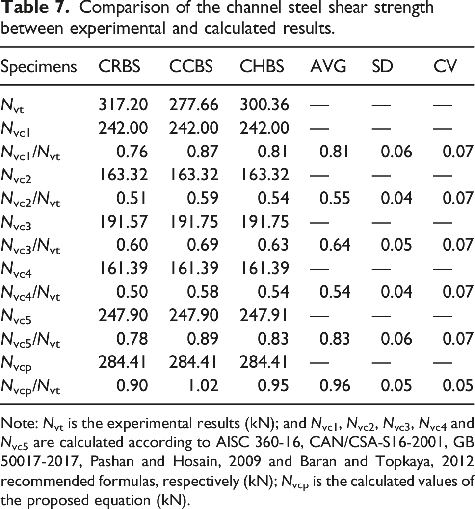
Note: Nvt is the experimental results (kN); and Nvc1, Nvc2, Nvc3, Nvc4 and Nvc5 are calculated according to AISC 360-16, CAN/CSA-S16-2001, GB 50017-2017, Pashan and Hosain, 2009 and Baran and Topkaya, 2012 recommended formulas, respectively (kN); Nvcp is the calculated values of the proposed equation (kN).
By comparing the data in Table 7, it was found that employing shear strength formulas of steel-concrete composite beam with channel steel shear connectors derived from national standards in this study would not be appropriate. Because the fracture of the channel steel connectors in the steel-concrete composite beam was a brittle failure due to the rigid connection between channel steel connector and steel beam. However, the channel steel connector was embedded in the PC beam and split-joint area, and a great plastic deformation occurred. Therefore, it should explore a different method from the above equations according to the crushing of normal concrete and the fracture of channel steel connectors.
For the newly developed beam-slab connection with channel steel connectors, the shear strength of the channel steel connector should be developed according to the failure mechanism of Figure 12 as follows. The effect of concrete failure on the PC beam side and channel steel connectors fracture was considered simultaneously when deriving the shear strength formula of channel steel connector.
Considering the concrete failure on the PC beam side, the principle of plastic analysis was used to establish the equation of the internal and external work balance, as shown in equation (17):


Considering that the channel deformation of this study was different from the steel-concrete composite beam (Baran and Topkaya, 2012), the influence height of channel steel is considered to be 0.25Hc, while the influence height of channel steel determined in this study was
Substituting equations (18)–(20) into equation (17) to get the final calculation method of shear strength for the newly developed beam-slab connection with channel steel connectors can be concluded as equation (21):
For the failure of channel steel fracture, equation (22) with the strengthening coefficient f4 of the channel steel flange was proposed to calculate the shear strength of the channel steel connector (f4 = 1.25).

The results calculated by equation (23) are shown in Table 7. It can be found that the test values were greater than the calculated value of the proposed formula, and the ratio between the calculated value and the test value was in the range of 0.90-1.02, with the mean value 0.95 and the coefficient of variation 0.05, showing that they were in good agreement. Thus, the proposed formula was suitable for the calculation of the shear strength of the PC beam and slab connected by channel steel with split-joint post-casting UHPC.
As shown in Figure 14, compared with different calculation methods, the shear strength equations proposed for studs/channel steel connectors in this study presented higher accuracy and provided a reference for designing the PC beam-slab connection with studs/channel steel connectors embedded in UHPC. Meanwhile, compared with other relevant studies (Fang et al., 2023; Jiang et al., 2021; Kruszewski et al., 2018; Liu et al., 2019; Yang et al., 2020), the formula proposed in this study had good applicability. Comparison results: (a) comparison between the experimental results and different shear strength calculation methods; and (b) comparison between calculated results and test results in relevant studies.
Conclusions
In this study, the shear performance of the new PC beam-slab connection with different connecting methods, connector reinforcement ratio and connecting width between two slabs was studied by the static push-out test. The following conclusions can be drawn based on the test and analysis results: (1) The PC beam-slab specimens of split-joint post-casting UHPC connected by stud/channel steel connectors both showed fracture of the connectors, and the crushing failure of concrete on the side of the PC beam. The absence of any noticeable cracks on the PC slabs’ side indicated the excellent compression behavior of UHPC. (2) The newly developed studs/channel steel connectors for PC beam-slab connection were reliable, which could effectively transfer shear force. The newly developed PC beam-slab connection had better slip performance and initial shear stiffness compared with traditional steel-concrete composite beams, and its characteristic slip met the ductility requirements of EC4. (3) The connector reinforcement ratio had an important effect on the shear strength of the PC beam-slab connection. Specimens with a high connector reinforcement ratio exhibited higher shear strength and interface slip than that with a low connector reinforcement ratio. In addition, the connecting width between two slabs and the slab type had little influence on slip performance and bearing capacity of PC beam-slab connections. (4) The shear stiffness of the stud/channel steel connectors in this study was obtained by formula in EC4. By comparing the calculation results of the shear stiffness, it could be concluded that the specimens using channel steel connectors had higher shear stiffness than those using stud connectors. (5) The enhancement coefficient of split-joint post-casting UHPC was introduced to consider the shear contribution of concrete, and the formula for calculating the shear capacity of stud connectors was proposed. Meanwhile, according to the shear mechanism, the calculation method of channel steel connectors was deduced by using the plastic analysis principle. The calculation results of the shear strength of the proposed formula were in good agreement with the test results. (6) The studs and channel steel connectors both had high bearing capacity and slip performance. However, considering that the studs would not break immediately during the failure process, they had excellent plastic deformation ability. Thus, it is recommended to use in practical to achieve a faster construction.
Footnotes
Declaration of conflicting interests
The author(s) declared no potential conflicts of interest with respect to the research, authorship, and/or publication of this article.
Funding
The author(s) disclosed receipt of the following financial support for the research, authorship, and/or publication of this article: This work was supported by the National Natural Science Foundation of China (Grant No. 52208160); the Natural Science Foundation of Hebei Province, China (E2021202012); and the Science and Technology Research Project of Higher Education Institutions in Hebei Province (CXY2023016).