
Abstract
This paper proposes an approach for finite element (FE) model updating and response prediction of frame structures based on optimal sensor placement (OSP), which integrates sensor placement optimization, mode expansion, and model updating techniques. Firstly, sensor optimization layout and modal testing analysis are conducted on a bolted laboratory frame structure. The covariance-driven stochastic subspace identification (SSI-COV) method identifies the real-world structure’s natural frequencies, modal damping, and mode shapes. Secondly, the complete mode shapes are expanded using the measured incomplete modal data from the limited number of sensors. Thirdly, a multi-objective function based on frequency and mode shapes is established to adjust the parameters of the FE model. This ensures that the updated model accurately represents the dynamic properties of the actual structure within a specific frequency range. Finally, the Rayleigh damping of the frame structure is estimated, and the damping matrix is assembled to enhance the accuracy of dynamic response prediction in the updated model. By comparing the response prediction results of the updated FE model with and without considering the updated damping effects to the measurement data of the real-world structure, it is demonstrated that the proposed method considering updated damping effects can more effectively predict the structural response.
Keywords
Introduction
In the field of structural health monitoring, establishing an accurate benchmark finite element (FE) model is essential for predicting structural responses, issuing safety warnings, and ensuring long-term monitoring and safety assessment (Ai et al., 2023, 2024; Bi et al., 2023; Girardi et al., 2020; Lye et al., 2021). Discrepancies between dynamic properties derived from the initial FE model and field measurements, attributed to factors such as model simplification and uncertain structural parameters, impede the accurate simulation of the structure’s actual service state. Consequently, effective methods are needed to update the initial FE model’s parameters using the measured data to improve the accuracy of predicting the structural dynamic response, thereby enhancing the significance of structural dynamic simulations.
The FE model updating methods using the vibration measurement can be classified into two categories, i.e., time domain-based and modal domain-based (Esfandiari et al., 2010; Liu et al., 2018). For the time domain-based methods, Song et al. (2020) presented two adaptive Kalman filters for nonlinear model updating; their performance has been verified through numerical applications and compared to that of a non-adaptive unscented Kalman filter and an existing dual adaptive filter. Seventekidis et al. (2020) investigated a novel damage detection method in which data is solely derived from FE calculated responses, after an initial experiment for FE model updating on the healthy structure state. Baybordi and Esfandiari (2022) proposed a straightforward sensitivity-based model updating approach. They achieved a linear relation between the variation of the unknown structural parameters and time history responses. Also, the Machine learning–based methods (Mousavi et al., 2021; Yuan et al., 2023) and Bayesian-based methods (Kitahara et al., 2021; Sengupta and Chakraborty, 2023) have also received much attention in model updating in the time domain.
The modal domain-based methods have been developing rapidly and are widely applied to FE model updating, which updates the structural parameters of the FE model through an optimization process by establishing the objective functions of the modal parameters. Thus, the modal domain-based model updating methods usually incorporate experimental/operational modal analysis, modal condensation/expansion, and optimization algorithms. Due to the structural damages usually manifest themselves as changes in the modal parameters of the structure, such as modal frequency, mode shape, and modal strain energy. Based on these phenomena, the modal domain-based FE model updating methods are widely studied for structural damage detection (Chen and Maung, 2014; Das and Debnath, 2020; Ghannadi and Kourehli, 2019; Jaishi and Ren, 2006; Nasery et al., 2020; Park et al., 2019). Also, the updated FE models can represent an indispensable tool to predict the structural response during its overall service life. Chouksey et al. (2013) updated an actual rotor system mounted on ball bearings by using the inverse Eigen sensitivity method. The experimental results show that the updated finite element model of the rotor system can be efficiently used to predict the unbalance in the rotor. Lin et al. (2018) proposed a dynamic simulation approach based on a well-designed structural monitoring system; the results demonstrated that it can reproduce the structural responses of large-scale straight-bladed vertical-axis wind turbines satisfactorily. Song et al. (2019) conducted a hierarchical Bayesian model updating approach for response prediction of dynamic structural systems; the effectiveness of the method was verified through a 10-story building model.
The FE model with a large number of degrees-of-freedoms (DOF) which is not always possible to measure all DOFs of a finite element model due to the limited number of sensors in practice. Thus, the effectiveness of FE model updating mainly depends on the type, number, and locations of sensors placed on the structure. Optimal sensor placement (OSP) is to determine the best sensor configuration that maximizes the information gained about the instrumented structural systems (Pei et al., 2019; Tan and Zhang, 2020). Some researchers have proposed OSP approaches for FE model updating (Batou, 2015; Cheng et al., 2009; Chow et al., 2011). Djatouti et al. (2021) proposed goal-oriented OSP and FE model updating strategies to accurately compute quantities of interest in thermal building problems. Tamizifar et al. (2022) presented an optimal sensor placement technology for updating a nonuniform wind turbine tower model better to predict the actual structure’s dynamic and vibrational behavior. The results show that the updated mode had less than 1 % error compared to the measured frequencies. Bagirgan et al. (2023) investigated an iterative OSP framework for structural identification and model updating of structural systems using a small number of mobile sensors, where the FE model updating is performed based on the Bayesian inference approach.
FE model updating techniques have seen significant progress in recent years. However, most methods do not consider the effects of the damping matrix during the updating process, which poses a challenge in accurately simulating the dynamic behavior of structures under external loads. Consequently, the predicted response of the updated model may still need to be validated compared to the actual structures. In this context, this study proposes an approach for FE model updating and response prediction of a target structure based on optimal sensor placement. The effective independent-drive point residue method is used for the sensor placement optimization and a modal expansion technique is adopted to expand measured modes to meet the spatial completeness requirement. The EF model is updated by minimizing the difference between the measured and simulated modal properties. A Rayleigh damping assumption is provided and identified from the measured response for more accuracy in predicting actual structures. To validate the proposed approach, an experiment is conducted on a five-story frame structure to demonstrate its effectiveness and performance in accurately updating the structural FE model and predicting the structure’s dynamic response under external load despite limited measured data.
Methodology
Optimal sensor placement
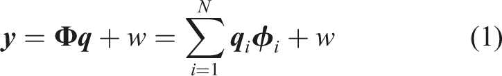
Due to the multi-DOF structure and a limited number of sensors, a crucial challenge in vibration testing is to place the limited number of sensors in optimal locations to obtain accurate modal information for the subsequent FE model updating. The effective independent (EFI) method (Kammer, 1991) aims to systematically reduce the DOF with minimal contribution to the target modal vector from all measurement locations, maximizing the linear independence of the target mode shape matrix with a limited number of sensors. Based on the principle of modal superposition, the sensor output information
As mentioned earlier, the EFI method is to select measurement locations that make the mode shapes of interest as linearly independent as possible while containing sufficient information about the target modal responses, and this process is an unbiased estimation. Thus, the covariance matrix of the estimate error can be written as:
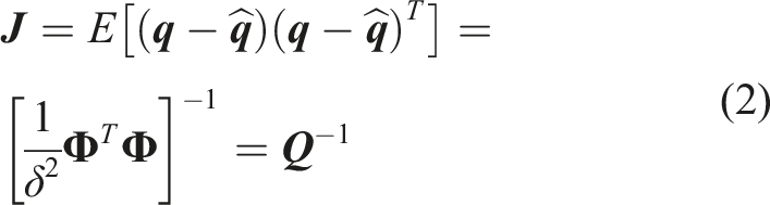
The covariance matrix
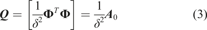
The EFI method sorts the priority order of each candidate measurement location based on the magnitude of the diagonal elements of the constructed effective independent distribution

The EFI method is one of the most influential sensor placement algorithms; its drawback is that sensor locations might be chosen with less energy content, resulting in the signal-to-noise ratio of measurement responses is low. The effective independent-drive point residue (EFI-DPR) method proposed by Wu et al. (2007) utilizes a strategy of creating modal kinetic energy distribution diagrams for each target mode of the structure. Subsequently, sensors are strategically positioned in locations characterized by higher modal kinetic energy, enhancing parameter identification and boosting the signal-to-noise ratio for modal identification purposes. The residual coefficient of the drive point is defined as follows:
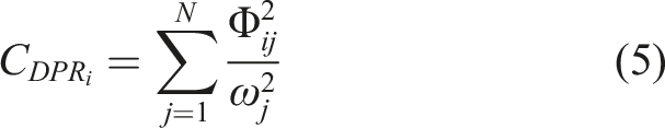
Therefore, the EFI-DPR coefficients of the candidate sensor locations can be represented as follows:
The EFI-DPR method considers the effect of vibration mode energy distribution in sensor placement optimization, thereby overcoming the potential drawback of information loss in the EFI method. The EFI-DPR selection process is sorting the
Experimental modal expansion
The limited DOFs measured based on the optimal sensor placement for the structure necessitate the utilization of an interpolation modal expansion method (Lipkins and Vandeurzen, 1987) to extend the measured modes to fulfill the spatial completeness requirement. Assuming that each mode is composed of a linear combination of the analytical modes, it becomes possible to derive the complete coordinates in the experimental model. Selecting the analytical modes enables expressing the rth experimental mode as follows:
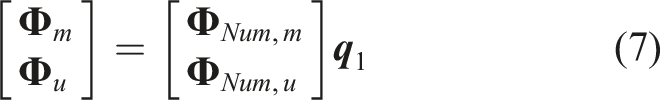

Combing equations (4) and (5), The unmeasured DOFs of the experimental structure can be further expanded with:

Based on the aforementioned analysis, the unmeasured DOFs of the experimental mode shape can be extrapolated using the mode expansion method that combines the analytical and measured mode shape vectors obtained through optimal sensor placement.
Finite element model updating
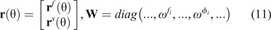
The initial Finite Element (FE) model requires update through adjusting its structural parameters, such as stiffness, using measurement data to more accurately portray the real-world structural state. Consequently, the FE model updating process can be described as an optimization problem, and the objective is to find the best parameter estimate for the unknown structural parameters by minimizing discrepancies between analytical and experimental modal data, including natural frequencies and mode shapes of the dominant modes. Here, the objective function can be defined as the sum of weighted least-square errors:

The FE model updating process entails searching for the optimal solution parameters to minimize the aforementioned objective functions. Once the parameters requiring updating are defined and the objective function is formulated, it becomes crucial to choose an appropriate optimization algorithm for iteratively updating the FE model. This iterative process aims to determine suitable parameter values that align the model’s calculated results with the measured ones. In this study, we employ the trust-region-reflective optimization algorithm for model updating as referred to in (Feng and Feng, 2016). It should be noted that the weighting factors for the residues should be selected based on their importance and measurement precision. Typically, frequencies extracted from measurements are more reliable than mode shapes, and thus, they should be given higher priority in terms of weighting.
The framework of the proposed method
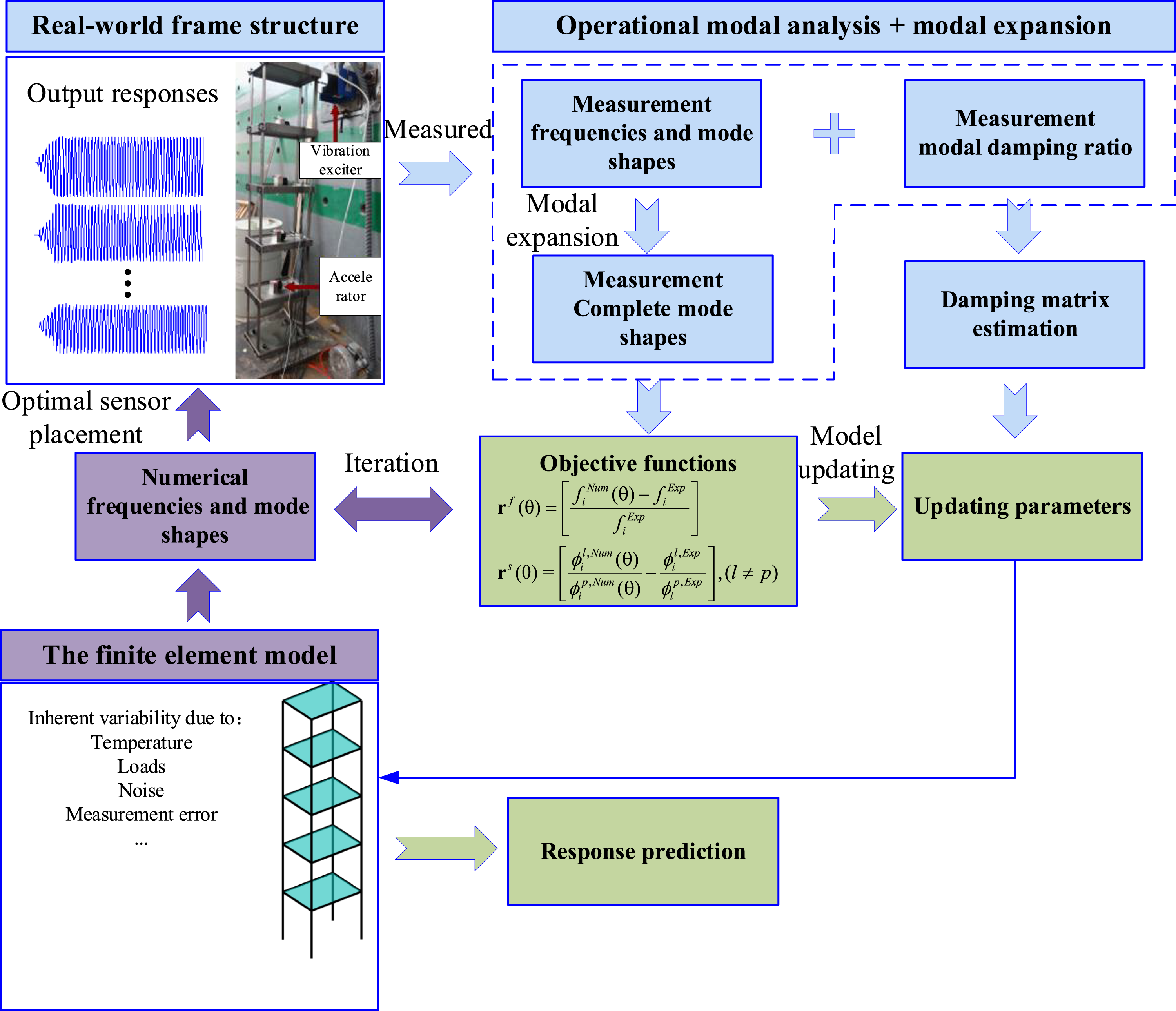
The holistic structure of the proposed method can be described as shown in Figure 1. The main procedure can be described as follows: Step 1: Sensor placement optimization. The initial FE model is established and utilized to calculate the eigenvalues to obtain the target modal matrix. Step 2: Modal expansion. The modal properties (frequencies, mode shapes, and modal ratios) are extracted by operational modal analysis, and the complete mode shapes are fulfilled through experimental and analytical modes. Step 3: The FE model updating. The multiple objective function is established through natural frequencies and mode shapes, and the selected physical parameters of the initial FE model are updated. Step 4: Response Prediction. The damping matrix is identified through frequencies and modal damping ratios and is considered in the updated FE model for response prediction. The holistic structure of the proposed method.
Application on a scaled frame structure
The five-story frame structure description
To validate the proposed approach, the model updating and response prediction of a five-story steel frame structure is conducted. Figure 2(a) shows dimensions of the frame structure. The column of the frame has a total height of 1.825 m with 0.35 m each story, and the dimension of each floor plate is 0.3 m by 0.4 m. Figure 2(b) shows the frame structure is performed with excitation applied at the top plate by a vibration exciter anchored to the laboratory reaction wall, and the structural base is attached to the test bench by 4 bolts. All the column bars and floor plates are made of the same steel material, the Young’s modulus E = 2.06 × 10⁵ N/mm2. Every story has four thin column bars riveted to the plate, and the theoretical lateral stiffness of each story is 47.17 N/mm. The frame structure can be idealized as a 5DOF system since every floor can be taken as a rigid mass, and the lateral stiffness is mainly provided by bending of the columns. The accelerometers are placed on the floor plates, then the mass of each story includes the floor plate and the sensor weight. The measurement mass of each story is as follows: m1 = 24.99 kg, m2 = 24.94 kg, m3 = 24.93 kg, m4 = 24.75 kg, m5 = 24.80 kg. During the exciter test, the sampling frequency of acceleration response is set to be 50 Hz. More detailed description of the experiment can be found in the literature (Xie et al., 2018). The five-story frame structure. (a) Dimensions of the frame structure (b) the laboratory frame structure.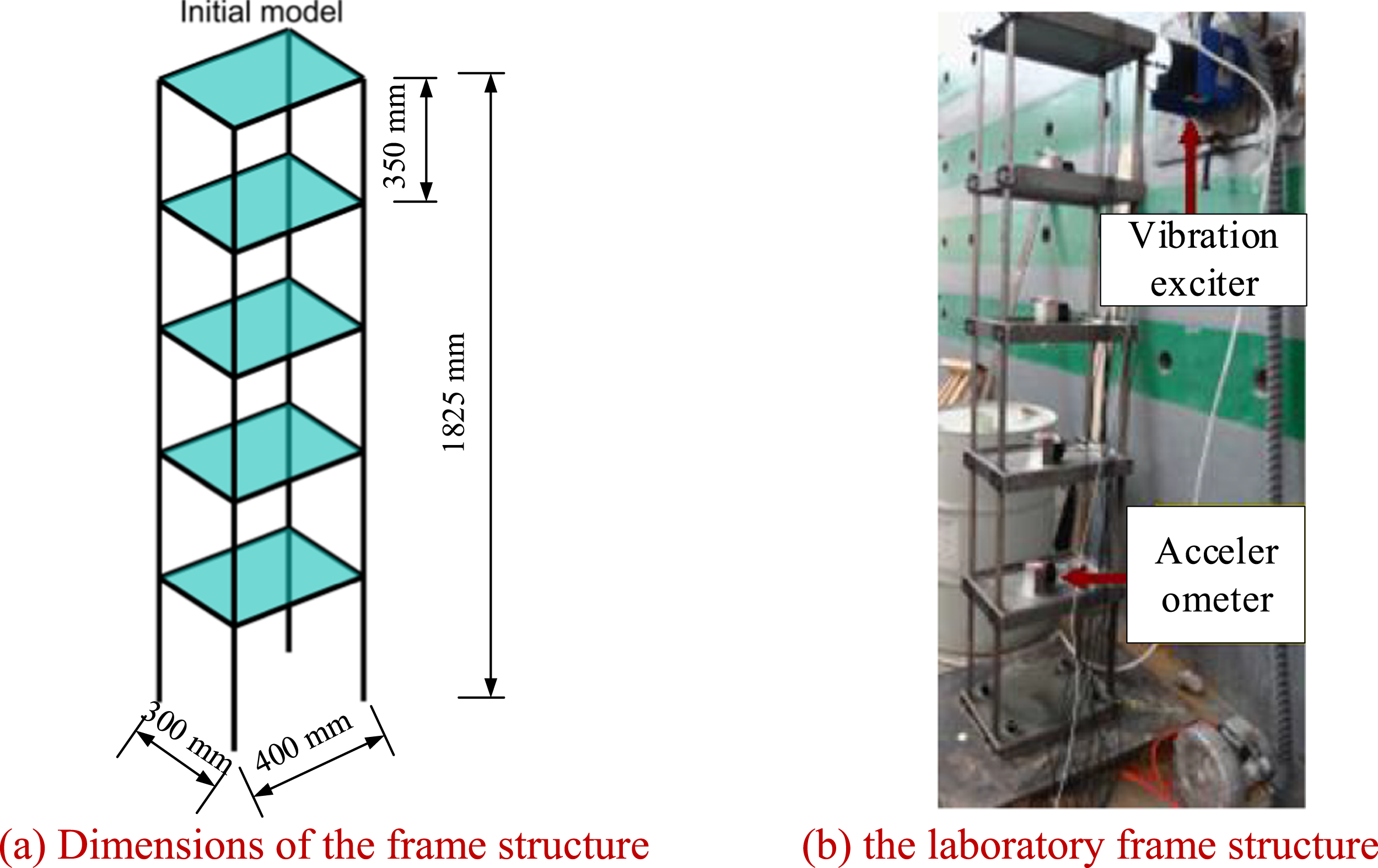
Sensor placement optimization
According to the above parameters of the frame structure, the mass matrix and stiffness matrix of the global structure are assembled. Subsequently, the corresponding five natural frequencies and mode shapes are presented in Figure 3. These modes are directly extracted from the eigenvalue analysis conducted on the initial FE model. The identified five natural frequencies are 1.947 Hz, 5.755 Hz, 9.072 Hz, 11.661 Hz, and 13.294 Hz, respectively. Here, the first five modes of the frame structure are chosen as the target modes for optimizing the placement of acceleration sensors, and the five floors are designated as potential monitoring locations for the optimized sensor placement. Frequencies and normalized mode shapes of the initial FE model. (a) the lst mode (b) the 2nd mode (c) the 3rd mode (d) the 4th mode (e) the 5th mode.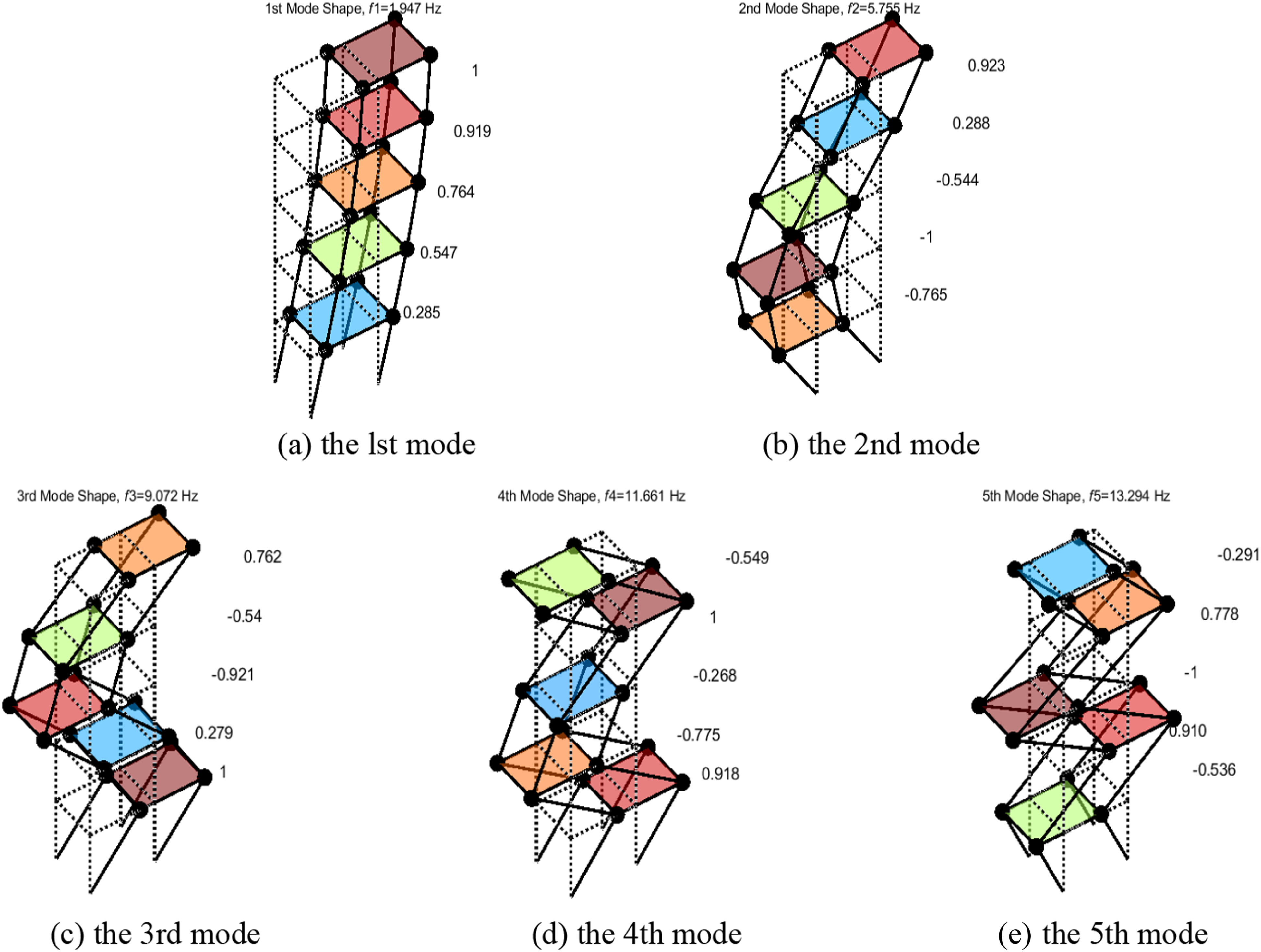
The analysis parameters for optimizing the accelerometer placement include the candidate positions for sensor placement and the number of sensors. The principle of QSP is to minimize the sensor count while ensuring the modal observability of the structure. Figure 4 shows the EFI-DPR method ranking of the five candidate sensor positions on the frame structure. It can be clearly seen that the most critical position for the acceleration sensor is the fifth floor, and the least essential sensor position is the fourth floor. Therefore, if only one sensor is to be installed, it should be placed on the fifth floor. Optimal layout of accelerometers for the five-story frame structure monitoring. (a) One sensor (b) Two sensors (c) Three sensors (d) Four sensors (e) Five sensors.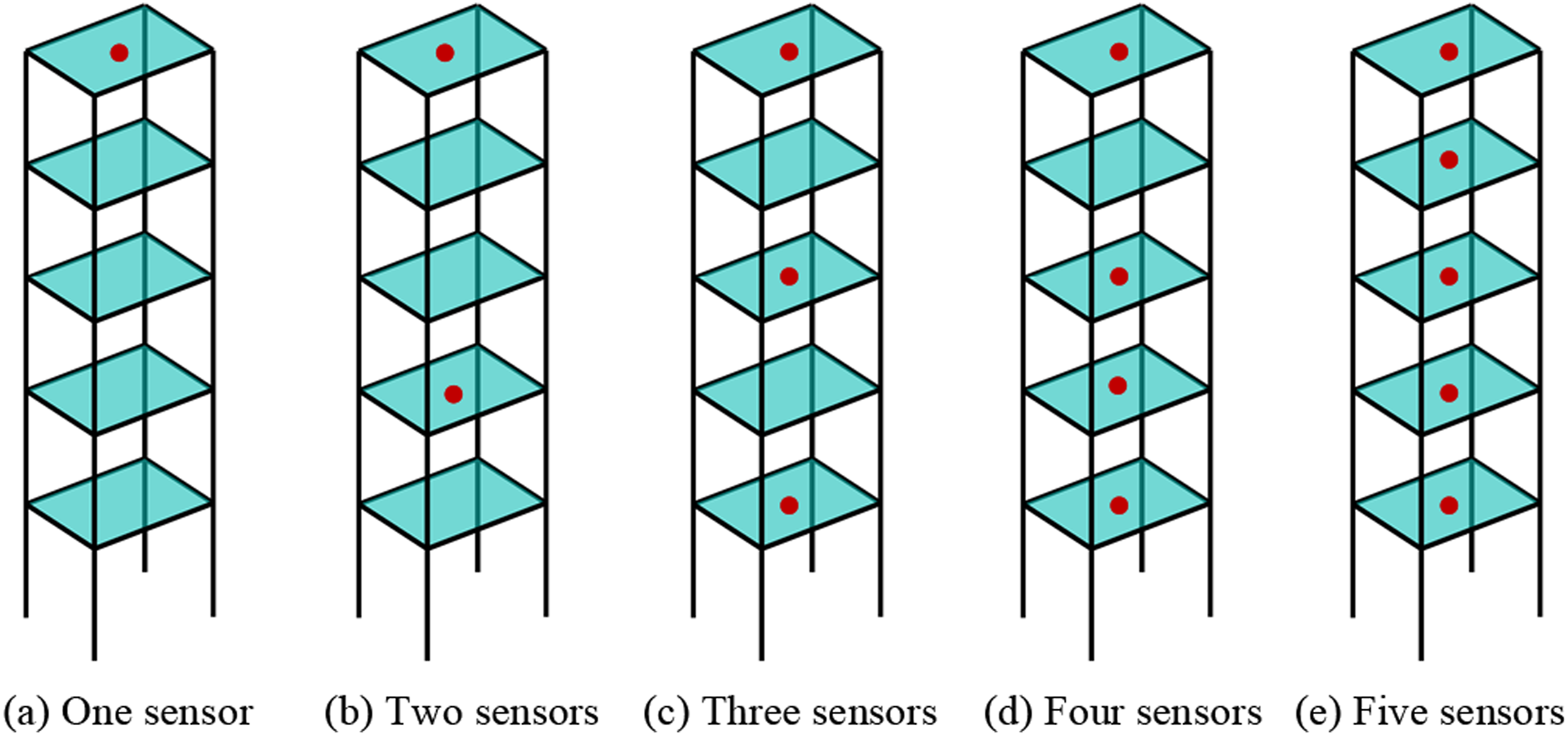
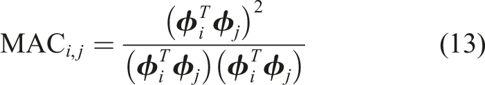
For sensor placement optimization, ensuring maximum linear independence of the structural mode shapes is crucial to represent the genuine modal properties of the tested structure accurately. In line with this principle, a criterion must be established to illustrate the interrelationship among the modes for OSP. Modal assurance criterion (MAC) is a suitable and popular tool for evaluating this linear dependence since it is easy to apply and does not need an estimation of the system matrices:
If the identified mode shapes of optimal measurement positions are orthogonal, indicating their easy distinguishability, then the off-diagonal elements in the MAC matrix should be less than 0.2. Lower off-diagonal values in the MAC matrix indicate higher independence among mode shapes at each measurement position. Consequently, optimizing sensor placement can be attained by minimizing the off-diagonal elements in the MAC matrix. Figure 5 shows the MAC plots of five modes for various optimal sensor layouts. It can be seen that the maximum MAC off-diagonal value decreases with an increase in the number of sensors of the OSP. In Figure 5(c), MAC values are high, and off-diagonal values closely approach zero with complete measurements by five sensors, indicating a strong independence of mode shapes. In 3 sensors layout case of OSP, sensors placed on the first, the third, and the fifth floors for measurements, the MAC off-diagonal values in small and quite large with the maximum value of 0.5427. However, the mean MAC off-diagonal value reaches 0.179, which is below the threshold of 0.2. This signifies the independence among the measured mode shapes. Comprehensive, the 3 sensor layout of the OSP is selected as the measurement system. MAC of the five modes for the frame structure based on OSP. (a) OSP with 3 sensors (b) OSP with 4 sensors (c) OSP with 5 sensors.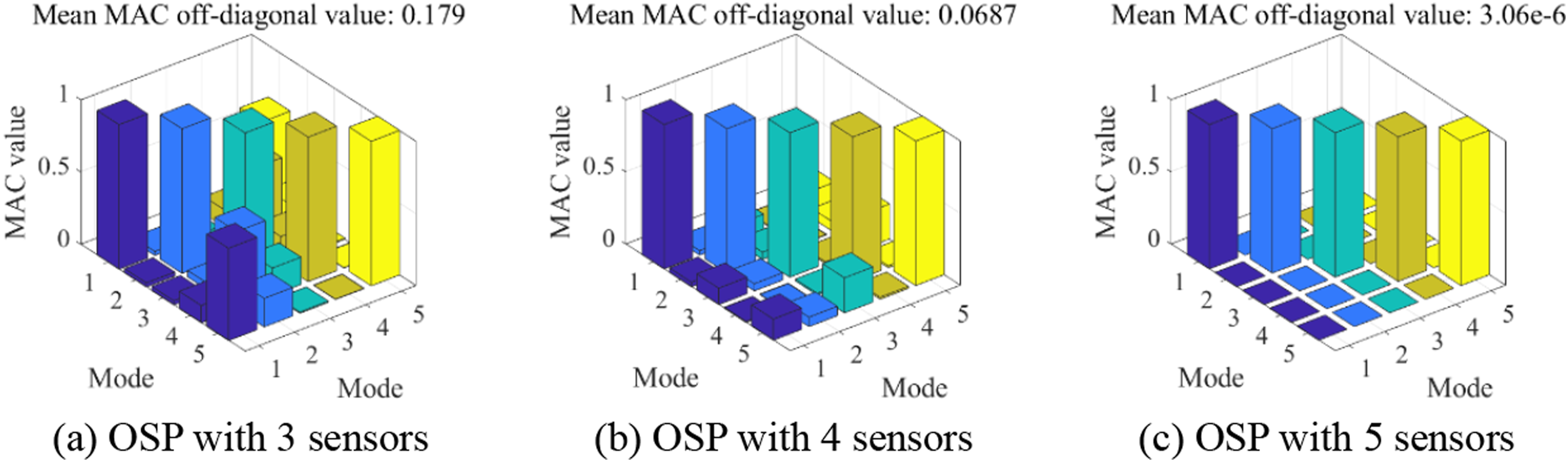
Operational modal analysis and modal expansion
The vibration tests were performed to identify the modal properties of the five-story frame structure, which will be used as the actual properties for updating the FE model. Three accelerators were installed on the surface of the stories in the transverse directions based on the optimal sensor placement. Figure 6 shows the input excitation and the ambient acceleration from the optimal sensor placement on the first, third, and fifth stories, respectively. Input excitation and measured acceleration responses. (a) input excitation (b) the first story (c) the third story (d) the fifth story.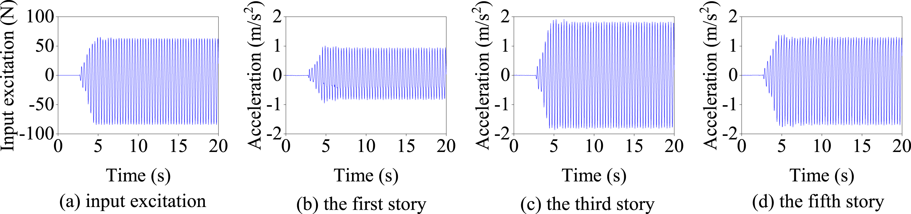
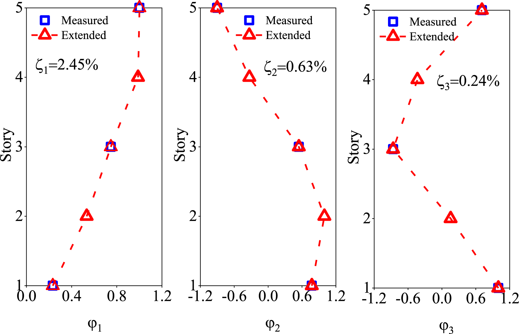
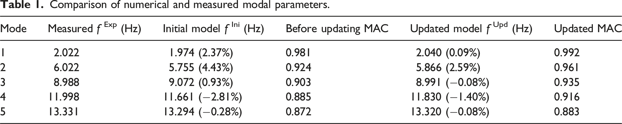
The output-only modal identification method, covariance-driven stochastic subspace identification (SSI-COV) (Cheynet et al., 2016), is applied to identify the modal properties (including natural frequencies, damping ratios, and mode shapes) from the measured acceleration responses. The stabilization diagram is utilized to eliminate spurious modes induced by environmental factors. Figure 7 presents the stabilization diagram resulting from the implementation of the SSI-COV method with limited acceleration records measured from the frame structure. Several criteria are employed to identify the modal properties: model orders range from 5 to 40; natural frequency variation<1%; modal damping coefficient variation <2%; minimum MAC coefficient between mode shape estimates 0.99. The first five modes are discerned from the diagram, derived from 3 accelerometer measurements, revealing the natural frequencies of the frame structure to be 2.022 Hz, 6.022 Hz, 8.988 Hz, 11.998 Hz, and 13.331 Hz. Figure 8 depicts the first three measured incomplete mode shapes and modal damping ratios, and the complete mode shapes by modal expansion are presented for comparison purposes. The experimentally identified mode shapes represented as blue points corresponding to the three-floor sensor positions, while the complete mode shapes are depicted as red dashed lines. It can be seen that the modal expansion technique successfully reconstructs the complete mode shape of the 5DOFs structure using the 3 accelerometer measurements. Thus, the combination of operational modal analysis and mode expansion presents a potent tool for mode identification. Furthermore, the damping ratios for the first three modes are determined to be 2.45%, 0.63%, and 0.24%, respectively. Stabilization diagram of the limited acceleration responses. Modal properties of first three modes of the frame structure.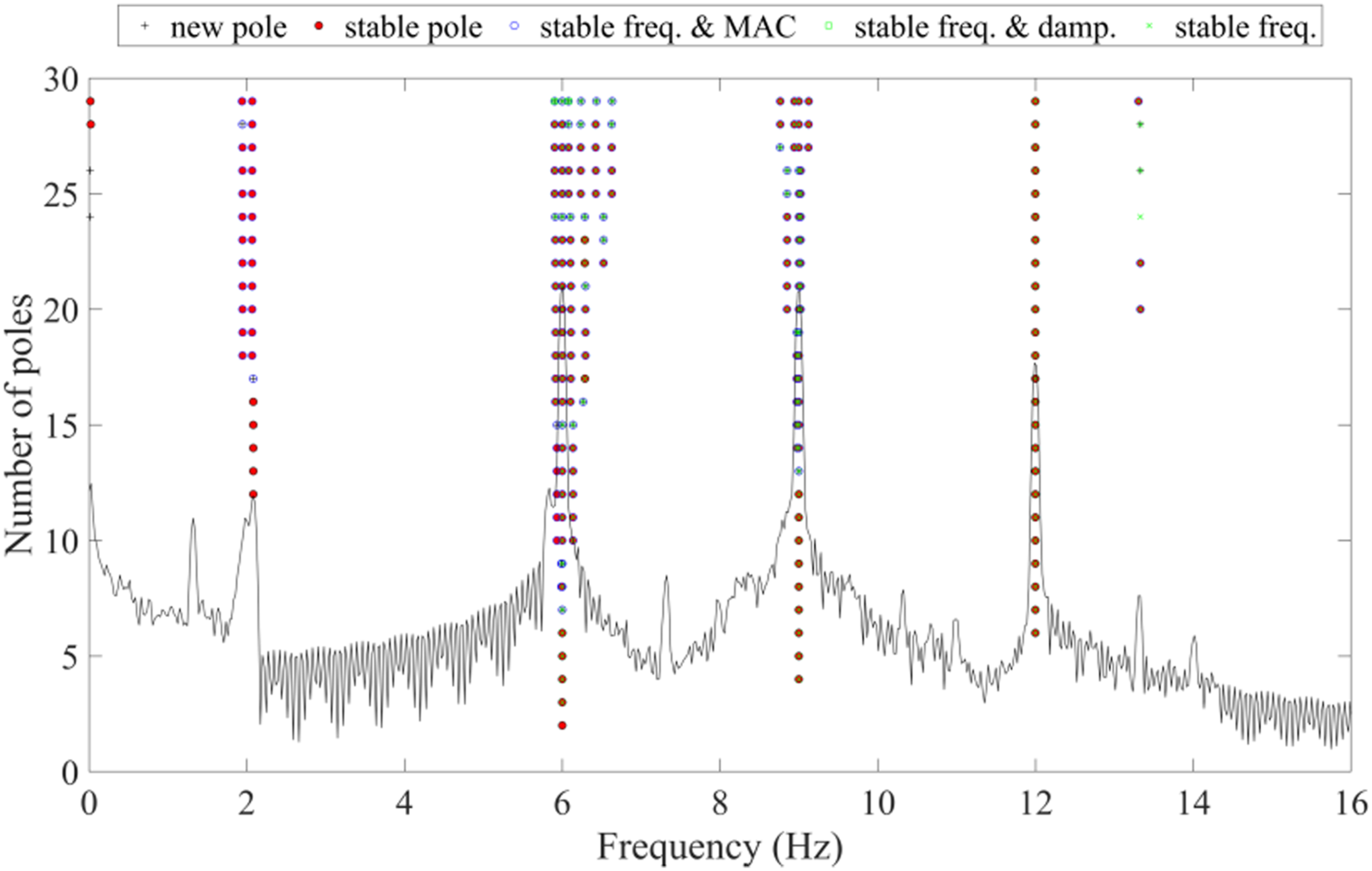
FE model updating
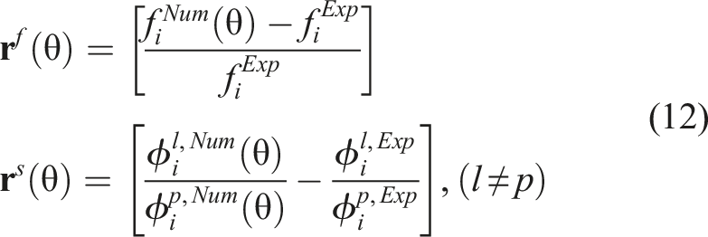
In practical engineering applications, the identification of high-order modes in actual structures is often challenging due to limitations in testing techniques, especially when the dynamic response of the structure under external excitation is small. This leads to a higher susceptibility of the measured high-order modes to noise interference. Hence, the first three modes are considered for FE model updating, and the objective function considering the frequency residual and mode shape residuals. Subsequently, the objective function and state variables are defined. Stiffness coefficients for the five-story frame structure, denoted as k1 to k5 from bottom to top, are chosen as parameters for updating. Given the presence of multiple parameters for model updating, the updated parameters represent reasonable estimates rather than exact values. Thus, the stiffness parameters’ ranges are constrained to ensure that the updated stiffness parameters reflect the actual structural conditions. The maximum variation of ±20% is set for the story stiffness, with the initial story stiffness of the FE model established at 47.17 N/mm. Additionally, the weighting matrix should be chosen in the objective function to reflect the relative accuracy among the measured modes, and it is usually determined by the importance and measurement accuracy of the measured modes. In the FE model updating process, a weighting factor of 1 is adopted for all frequency residues and 0.5 for all mode shape residues, with the story stiffness being iteratively estimated. The tuning process concludes when the tolerances of 10e-12 are achieved or after 500 iterations.
Figure 9(a) shows the updated coefficients for the story stiffness in the FE model updating. The results indicate that the first, second, and fourth story stiffness exhibit positive updated coefficients, implying that the ascertained stiffness values exceed the initial values. In contrast, the third and fifth story stiffness display negative coefficients. Specifically, the coefficient for the stiffness in the first story reaches 0.18. Figure 9(b) compares the five natural frequencies, both before and after updating, of the FE model and the measured frequencies. The natural frequencies of the updated FE model are closer to the measured frequencies of the real-world structure than those of the initial FE model. The results demonstrate that the proposed method achieves satisfactory accuracy and effectiveness in FE model updating. Updated parameters of the five-frame structure. (a) Updated stiffness coefficients (b) Results of the frequencies.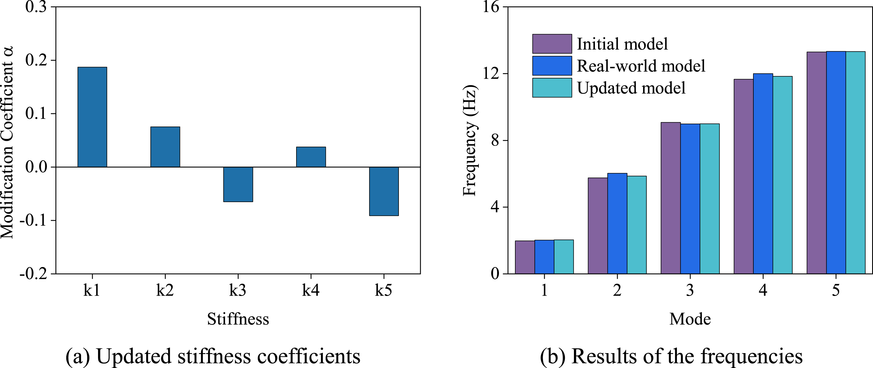
Comparison of numerical and measured modal parameters.
Response prediction considering damping effects
Damping matrix identification
During structural dynamic response analysis, the damping ratio plays a critical role in influencing the structural response, alongside frequency and mode shape. Damping is a challenging and crucial aspect of FE modeling. It is essential to include the damping ratio when calculating dynamic responses; neglecting it may lead to significant errors in predicting dynamic responses. There are two typical methods for determining system damping: one involves identifying the damping parameters through experimental test data, while the other entails establishing a specific damping model based on mathematical principles to simulate actual damping.
The continuous time equation of motion for the five-story frame structure is presented below:
Generally, proportional damping is assumed to describe the observed decaying motions of vibration. The term proportional indicates that the damping effects is in “some way” linearly related to the mass and stiffness properties. This linear relationship is known as Rayleigh damping and can be expressed as follows:
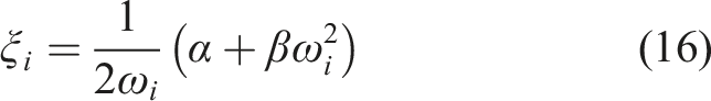
After identifying the modal damping ratios as ξ1 = 2.45% and ξ2 = 0.63% through operational modal analysis, along with the natural frequencies as f1 = 2.022 Hz, f2 = 6.022 Hz, equation (16) for the first two modes in matrix form leads to: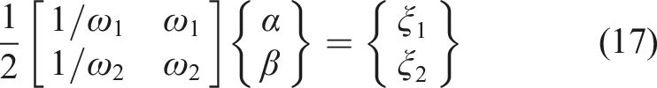
Upon solving the pair of algebraic equations mentioned, the coefficients α and β can be derived, allowing for the identification of the damping matrix of the frame structure and facilitating accurate prediction of the response.
Prediction results and discussion
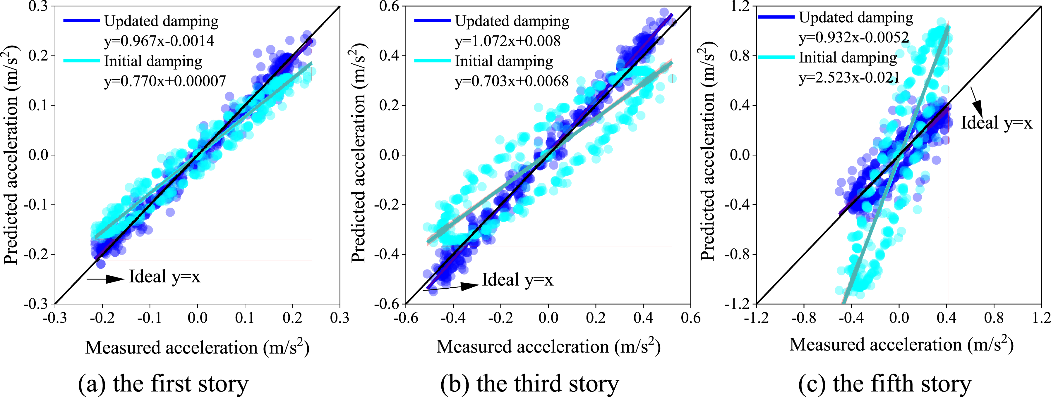
Once the damping matrix for the FE updated model has been updated, the response prediction is performed to evaluate the effectiveness of the proposed method. For this purpose, dynamic response tests are conducted on the actual structure, with the excitation point of the vibration exciter positioned at the top floor. The analysis includes studying the acceleration response prediction of the updated FE model, with and without incorporating the updated damping effects, in comparison to the measured responses. It is worth noting that the initial FE model has a damping ratio of 0.02 due to the steel frame construction. Figure 10 illustrates that the predicted accelerations generated by the proposed method closely align with the measured values, demonstrating a notably higher accuracy in comparison to the updated FE model that did not incorporate the damping effects update. The comparison between predicted acceleration and measurement data is depicted in Figure 11, illustrating the fitting results of the response prediction from the updated finite element (FE) model with and without the consideration of damping effects updating. It can be intuitively found that the updated FE model incorporating the updated damping effects yields the most accurate prediction results, displaying superior performance with a trend line closely aligned to the observed data line. Specifically, the fifth floor exhibits the poorest prediction result for predicted acceleration due to the application of input excitation, leading to a more pronounced acceleration response compared to the first and third floors. Overall, these results have further proved that the proposed method has a good effect on predicting the dynamic response, even with the limited number of sensors. Comparison of measured and prediction responses at different story. Comparison of prediction responses of the frame structure. (a) the first story (b) the third story (c) the fifth story.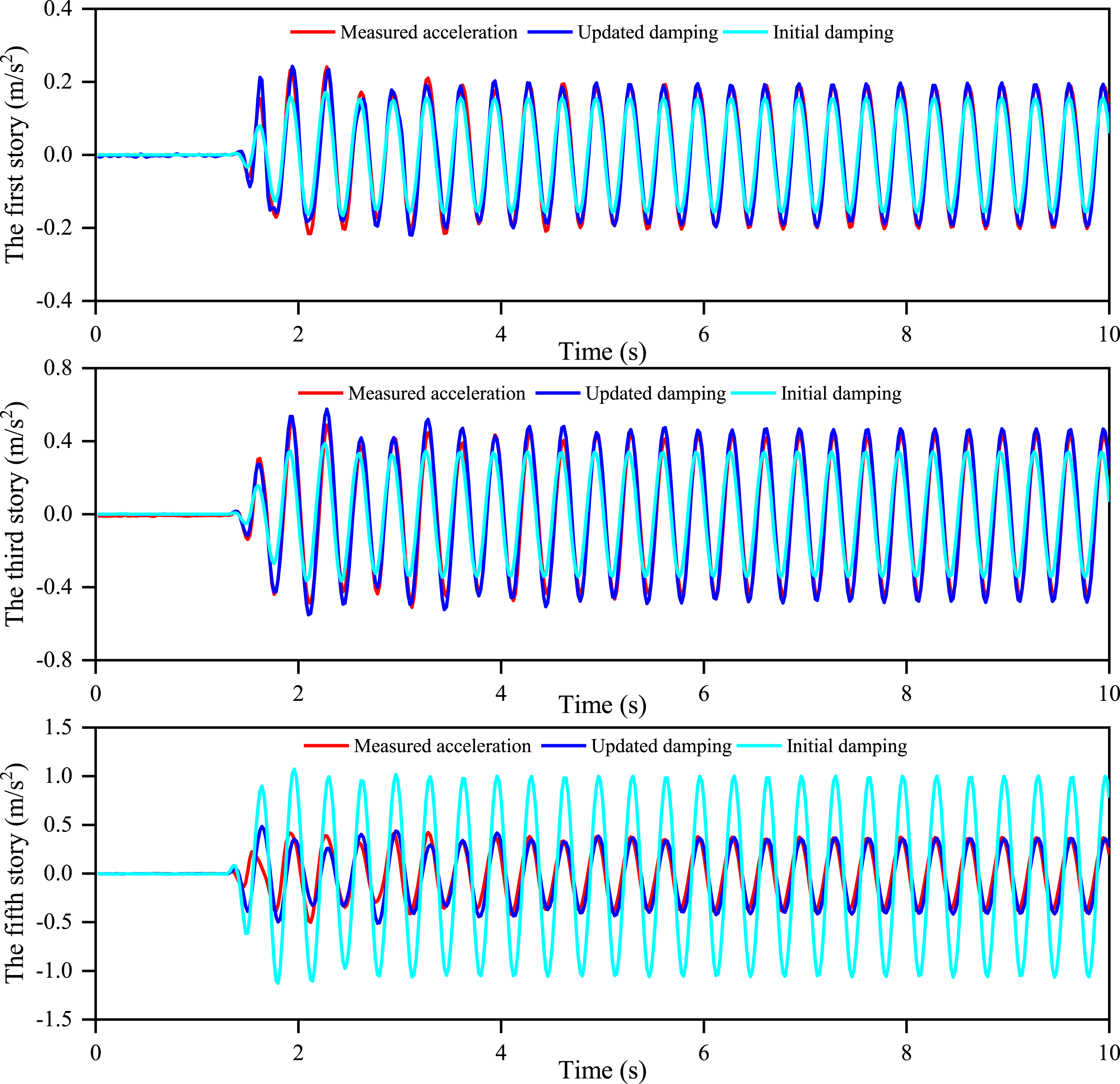
Conclusions
This study proposes an approach for finite element (FE) model updating and response prediction through sensor placement optimization and modal expansion. The effectiveness and practicality of this method were evaluated through experimentation on a five-story frame structure. Initially, the optimal sensor placement and quantity were determined using the EFI-DPR algorithm and Modal Assurance Criterion (MAC) for the monitoring system. Subsequently, the frame structure’s operational modal analysis was conducted using the COV-SSI method, and the complete mode shapes were identified with the measured ones using the modal expansion method. Parametric model updating was then employed to match the natural frequencies and mode shapes of FE modeling with the measured results, resulting in a significant improvement in correlation between the updated FE model and experimental modal properties with a minor relative error. Furthermore, the Rayleigh damping of the structure was identified based on the measured modal properties; considering the damping effects in the updated model led to a more accurate response prediction compared to the model that did not account for updated damping effects, showing a strong correlation with the measured response. These results demonstrate that the proposed method has the potential to deliver precise updated model and accurate predict response for practical engineering applications.
Footnotes
Declaration of conflicting interests
The author(s) declared no potential conflicts of interest with respect to the research, authorship, and/or publication of this article.
Funding
The author(s) disclosed receipt of the following financial support for the research, authorship, and/or publication of this article: This work was supported by the Key R&D program of Shaanxi Province (2023-YBGY-140 and 2020GY-096), the Traffic Scientific Research Project of Shaanxi Provincial Department of Transportation (22-53K and 23-46X), the Key R & D projects in Ningxia Hui Autonomous Region (2022BEG03173), and the Shaanxi Province Youth Science and Technology New Star Project (2022 KJXX-110).