
Abstract
For some long span cable supported bridges, the longitudinal diaphragms in main girder are designed as steel truss to reduce structural self-weight. However, unanticipated fatigue cracking in critical details of longitudinal steel truss diaphragm may occur after only a few years of service, resulting in stiffness weakening and stress redistribution. Based on an actual cable-stayed bridge, this paper presents a fatigue analysis of longitudinal steel truss diaphragms and provide an effective strengthening measure to elongate the fatigue life. Using traffic information from bridge toll station, the fatigue vehicle models were established. Then, a multi-scale finite element (FE) model was developed to help determining critical details of potential cracking and calculating the vehicle induced stress. After obtaining the required parameters, fatigue life of the specific critical detail was estimated base on damage accumulation law. The result agrees well with field observation. To ensure the performance of steel girder, the strengthening measure that replace diagonal tubes in longitudinal steel truss diaphragm with bolted channel steels was proposed and then applied. The assessment result indicated that the provided strengthening measure achieves satisfactory effects. It can also provide experience and partial reference for maintenance of similar structures.
Introduction
In the past several decades, a large number of long-span bridges were constructed in China. Most of these modern long-span bridges, including cable-stayed bridges, were designed with a steel box girder (Biezma and Schanack 2007; Fu et al., 2018). The steel box girder has many advantages such as high strength, light weight, good performance in earthquake resistance, etc. However, with the increase of span length and girder deep, the self-weight of bridge will significantly increase. Each component of steel box girder plays an important role, among them, longitudinal diaphragms were installed to increase structural stiffness, optimize the stress distribution in girder, and mitigate the damage of deck (Guo et al., 2015). In order to reduce self-weight of girder and improve internal ventilation, longitudinal diaphragms can be designed to be steel truss. However, defects of this structural form were also reported, especially near the connections of diagonal truss and gusset plate.
The most prominent problem of longitudinal steel truss diaphragm in cable-stayed bridges is unanticipated fatigue cracking, which even appeared after only a few years of service. The repetitive traffic load is a significant factor result in damage, fatigue cracks may continuously develop in an unnoticed way until reach a conspicuous length or width (Fang et al., 2023; Guo et al., 2012). The commonly used technique to detect fatigue cracks including visual inspection, magnetic particle testing, radiographic inspection, but all these methods can not judge and prevent potential risk at early stage (Mohammadkhorasani et al., 2023). Some previously study attempt to investigate the cracking mechanism. Existing test results showed that fatigue strength of welded gaps of a steel member was related to regional distortion, even small distortions with magnitudes will induce high cyclic stress ranges (Wang and Wang 2023). The stress concentration at vulnerable detail was a direct reason of cracking (Fang et al., 2021). Utilizing the correlation of the cracking rates and distortion field at crack tip, intensity factor can be used to represent the fatigue cracking growth driving force (Kamaya and Kawakubo 2012). Based on crack propagation theory, Liu et al. (2023) calculated stress intensity factors at the crack tip in welded toe of orthotropic steel bridge deck, the whole process of propagation and extending direction can be determined by maximum energy release criterion. Lesiuk et al. (2020) investigated the mixed-mode fatigue cracking in bridge steel after 100 years operational time, the mechanism of crack growth in old bridge steel under various complex loads was analyzed.
In view of that massive fatigue cracking at steel truss diaphragm may weaken the stiffness of steel girder and change stress distribution of deck, hence influence bridge performance. To delay the crack developing, various methods were proposed. The conventional methods include drilling a crack-stop hole at the end of crack, using plug welding to join the crack, covering the crack with a welded steel plate, and strengthening the entire bridge to prevent large deformations of the bridge (Liu et al., 2010). Obviously, strengthening the entire bridge is a costly option. Up to now, drilling a crack-stop hole is the simplest way, but only provides a temporary solution. After treatment of an original fatigue crack using a crack-stop hole, there still have the possibility of cracking again (Chen et al., 2023; Fu et al., 2017). Similarly, using plug welding or welded steel plate will occur re-initiation of the fatigue cracks as well. Other treatment methods were also explored. For instance, Alemdar et al. (2012) bonded carbon-fiber reinforced polymer on welded connections to prevent and repair fatigue damage, the evaluation results showed the fatigue life can be significantly extended. Deng et al. (2023) proposed an easy-to-implement strengthening measure in actual bridge, that is bonding reinforcing plates on deck surfaces to mitigate fatigue cracking in steel girder. Xin et al. (2023) used a CFRP prestressed reinforcement method, that effectively inhibited fatigue crack growth at the rib to deck joint and does not significantly increase the dead weight. However, more potential retrofit methods are still worth exploring.
On the other hands, the fatigue assessment of steel bridges is also a concerned aspect to ensure structural reliability (Zhu and Zhang, 2018). The S-N curve based methods are most widely adopted in current steel structure standards for the advantages of easy to understand and practical operate (Sheng et al., 2022). Besides, many researchers have made contributions (Zhang et al., 2021; Zong et al., 2015). Mustafa et al. (2023) simulated several commonly found fatigue damages at bridge details, then presented a method to evaluate fatigue damage in an existing bridge using the moving vehicle induced response. Considering different cracking mechanisms of crack initiation and propagation, Wang et al. (2023) attempted to accurately predict local cyclic elastoplasticity of crack and then assess the fatigue crack propagation life, the proposed method was verified by fatigue experiment results of rib-to-deck welded joint. In view of uncertainties during fatigue damage diagnosis for orthotropic steel deck, the dynamic Bayesian network-based probabilistic model was established to predict the crack growth, and can even be used to deal with the whole deck system consisting of many joints after updating traditional algorithm (Heng et al., 2019; Zhu et al., 2019). Intelligence methods have also been used to predict fatigue life. For instance, Jiang et al. (2021) presented a digital twin-driven framework for non-deterministic fatigue assessment of steel bridges, the established probabilistic multiscale model was used to depict the fatigue evolution during bridge service period. Anyway, fatigue assessment is an effective way to study fatigue performance, it is useful in management and maintenance of existing bridges (Kwon et al., 2012).
In existing research, more attention was paid to rib-to-deck cracks in steel girder, investigations on other components were relatively insufficient. Meanwhile, few strengthening measures were provided after fatigue assessment. This paper presents an actual case of fatigue analysis for longitudinal steel truss diaphragm in a cable-stayed bridge, then provide an effective strengthening measure to elongate the fatigue life of components. According to the field inspection records of Nanjing Dashengguan Yangtze River Bridge (NDYB), fatigue cracking status of longitudinal steel truss diaphragms was investigated. Then, an analysis procedure base on Miner’s damage accumulation law was provided. Traffic information from toll stations was used to obtain actual fatigue vehicle models of the case bridge. A multi-scale finite element model was also developed to help determining critical details of potential cracking and estimating fatigue lives. In view of that conventional crack-stop hole failed to prevent the crack extending, the suitable strengthening measure that replace diagonal weld steel tubes in longitudinal steel truss diaphragm with bolted channel steels was applied. The fatigue life after retrofitting was estimated to evaluate the effectiveness. The results also provide experience and partial reference for maintenance of similar structures.
Description of the cable-stayed bridge
Nanjing Dashengguan Yangtze River Bridge
The NDYB, opened to traffic in 2005, is a cable-stayed bridge that connects two districts cross the Yangtze River in Nanjing, China, as shown in Figure 1(a). It has a main span of 648 m and two symmetric side spans of 320 m, respectively. The 215 m height tower is designed to arc shape steel tower, which is the first of kind application among such long-span bridges worldwide (Fan et al., 2020b). As shown in Figure 1(b), the deck is designed as bidirectional six lanes, among which the outside lanes are usually for heavy trucks. The main girder is 3.2 m deep and 37.5 m wide orthotropic steel box-girder, which consisted of 89 prefabricated segments ranged from 6 to 15 m. All the components of girder used the Q345D grade steel, which indicates its nominal yield should be more than 345 MPa (GB/T 1591-2018, 2019; Su et al., 2019). For a typical girder segment, the top plate is 14 mm thick (thickening to 16 mm near the outside lanes) with 8 mm thick U-rib, the bottom plate is 12 mm thick with 6 mm thick U-rib, and the web plate is 30 mm thick. Several chambers are separated from a girder segment by crisscrossed diaphragms to increase sufficient stiffness. These are two series of longitudinal diaphragms in box girder, which are 15.2 m apart. In view of reducing structural weight, longitudinal diaphragms in the most area of the NDYB is designed to steel truss, see Figure 1(c). The longitudinal steel truss diaphragms are approximately located under the middle lanes. The upper and lower chords are used T-beams, and the diagonal is welded connected by steel tubes with an outer diameter of 203 mm and a thickness of 6.5 mm. There are a total of 1034 steel tubes for the whole bridge. The Nanjing Dashengguan Yangtze River Bridge (unit: mm, if not specified): (a) layout of bridge; (b) cross section of the steel box-girder; (c) the typical longitudinal steel truss diaphragm in a chamber.
Field inspection
To monitor the service status of bridge, a sophisticated structural health monitoring (SHM) system was installed in the NDYB. However, all types of sensors are failed to obtain effective information about cracks at longitudinal steel truss diaphragm. Strain gauges in girder collect data only from top and bottom plate. Hence, a professional engineering team is also employed to conduct periodic visual inspection using various equipment. The cracks of longitudinal steel truss diaphragm were observed in 2008 for the first time. According to detailed annual field inspection records from 2011, typical fatigue crack modes of longitudinal steel truss diaphragm, mainly including longitudinal crack, circumferential crack and through crack, are shown in Figure 2. Typical inspected cracks of longitudinal steel truss diaphragm: (a) longitudinal crack; (b) circumferential crack; (c) crack with stop hole; (d) through crack.
Cracks in longitudinal steel truss diaphragm were all observed near the connected gusset plates, and more cracks can be found in the segments that farther away from towers. The length of them ranged from several to hundreds of millimeters (5∼600 mm in 2013). Among them, a small portion of cracks distributed longitudinally along the weld seam (i.e., 1.18%), seen Figure 2(a), they are 10∼150 mm in length, and will eventually result in disconnection of the tube with gusset plate. These longitudinal cracks may be in connection with weld defect, such as porosity, inclusion, burn-through, and lack of penetration (Luo et al., 2023). But most of cracks were initiated at the welding hole, where is also the region of stress concentration under the repeated traffic load, and then propagated along the circumference of steel tubes (i.e., 87.59%), seen Figure 2(b). Besides, there also exist a small number of oblique cracks (0.24%), that are 10∼20 mm in length. In order to prevent or at least delay the component deterioration in a period, the bridge management department drilled crack-stop holes at the tips of these rapidly extending cracks, seen Figure 2(c). However, cracks always crossed the crack-stop hole and re-propagated along the previous trend after about 1 year. In addition, the timing of drilling the crack-stop hole will significantly influence the maintenance effect. For a similar case in existing studies, the best opportunity was when the crack reaches about 50 mm (Liu et al., 2020). The circumferential cracks ultimately grow into those through cracks, which cause fracture of the steel tube, as shown in Figure 2(d). Observing these through cracks, the fracture surfaces were relatively smooth, with no obvious textural property, and gleamed as caught the light.
Statistics of Cracks in Steel Tubes.
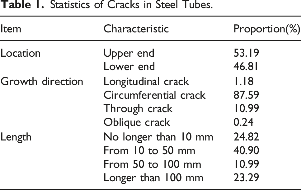
Based on the preliminary investigation, the observed cracks at steel tubes were not related to materials, but rather to local stress of the girder. In this paper, some potential reasons are analyzed as following: • Design defect of the longitudinal steel truss diaphragm: due to the high stiffness of upper and lower chords, the truss cannot form a hinge at junction and is difficult to adapt to local elastic deformation of structure under external loads (Alemdar et al., 2014; Guo et al., 2016). As shown in Figure 3, under a passing wheel load, the caused deformation trend will lead to significant secondary bending moment that is concentrated at junction of the plate and truss diaphragms. • Treatment of weld detail: the diagonal steel tubes are insert to gusset plate, and then connected with fillet weld seam. There are obvious defects such as welding slag and overlap near the gap, which make the junction of truss diaphragm and plate a critical part of fatigue analysis. • Cyclic load of vehicle flow: the longitudinal steel truss diaphragm is always located below the middle lane, a large number of heavy vehicles passed directly on it. Therefore, the vehicle induced cyclic load is one direct source of fatigue cracking (Zeng et al., 2022). • Complex operational environment: as a flexible structures, the long-span cable stayed bridge suffer from various time varying effects in service period, including wind, thermal actions, etc. All these factors result in extremely complex working condition of longitudinal steel truss diaphragm. Deformation and bending of truss diaphragm under wheel load: (a) deformed trend; (b) bending moment diagram.

Fatigue analysis
Fatigue analysis procedure
To study the cracking mechanism and estimate the fatigue life of longitudinal steel truss diaphragm, an analysis procedure base on the S-N curves and Miner’s law for fatigue damage accumulation is provided. The S-N curves that usually derived from extensive experiments are used to represent the relationship between fatigue life and specific stress ranges. It still be widely used around the world for fatigue analysis and have been set in many design codes. For instance, in the standard BS 5400 (2005), the S-N relationship can be obtained from either of the following:

To evaluate the fatigue damage in variable stress range, the Miner’s law for damage accumulation is used. The parameter D can be defined to be the summation of fatigue damage caused by various stress range, as the following expression: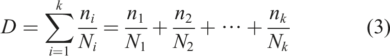
The fatigue analysis procedure in this study based on damage accumulation for longitudinal steel truss diaphragm is shown in Figure 4. The periodic field investigation should be conducted to monitor the cracking of components. To obtain actual fatigue vehicle models required for structural response simulation, traffic data collected by vehicle weighing system in bridge toll station need to be analyzed. Meanwhile, existing standards are adopted to determine the class of structure detail and corresponding calculation parameters. Utilizing the established FE model, the stress distribution and time history for critical detail of the longitudinal steel truss diaphragm are analyzed. The time history for a specific fatigue vehicle can be calculated by applying the vehicle load to the influence line obtained from the FE model. Then the stress ranges are obtained by rainflow counting algorithms (Downing and Socie 1982). With the Miner’s law for damage accumulation, the fatigue damage of each stress range is quantified, and the fatigue life of component can be estimated. In addition, according to the investigation and analysis results, suitable maintenance suggestions and strengthening measures can also be proposed to provide partial references for bridge management department. Fatigue analysis procedure for longitudinal steel truss diaphragm.
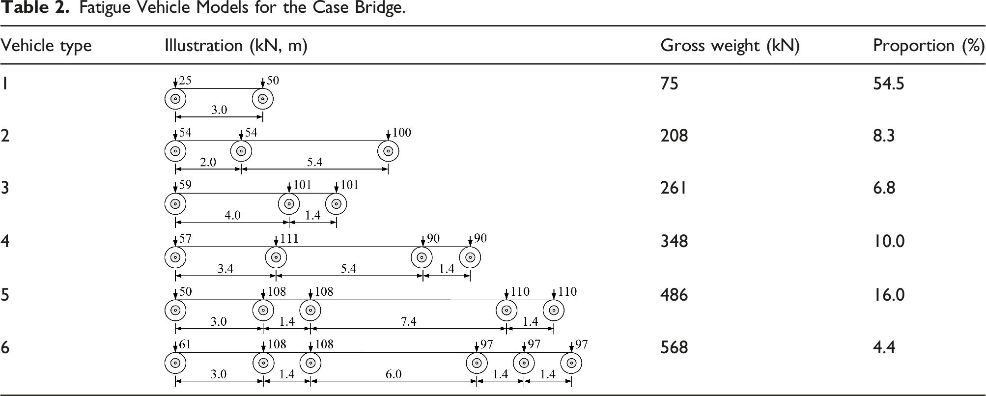
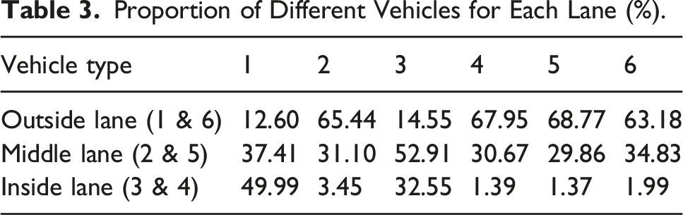
Fatigue vehicle models
Fatigue Vehicle Models for the Case Bridge.
Proportion of Different Vehicles for Each Lane (%).
In addition, the traffic volume should be analyzed to evaluate fatigue damage in a period. The monthly and annual average daily traffic volume from 2006 to 2019 is shown in Figure 5. In addition, when the NDYB just opened to traffic in 2005, the average daily traffic volume was about only 5000. With the completion of the bridge, the traffic flow showed a significant increasement in the first several years. However, this increase trend is not obvious recently. Considering some newly constructed bridges and underwater tunnels near the case bridges have been finished in recent years, the traffic volume is not expected to further increased (Ren et al., 2021; Xu et al., 2021). In this paper, the recorded actual traffic data during 2005 to 2019 is used, and the estimated average daily traffic volume of 35,000 is adopted after 2019. However, it should be admitted there may exist a certain deviation of the estimation. The recorded average daily traffic volume of Nanjing Dashengguan Yangtze River Bridge.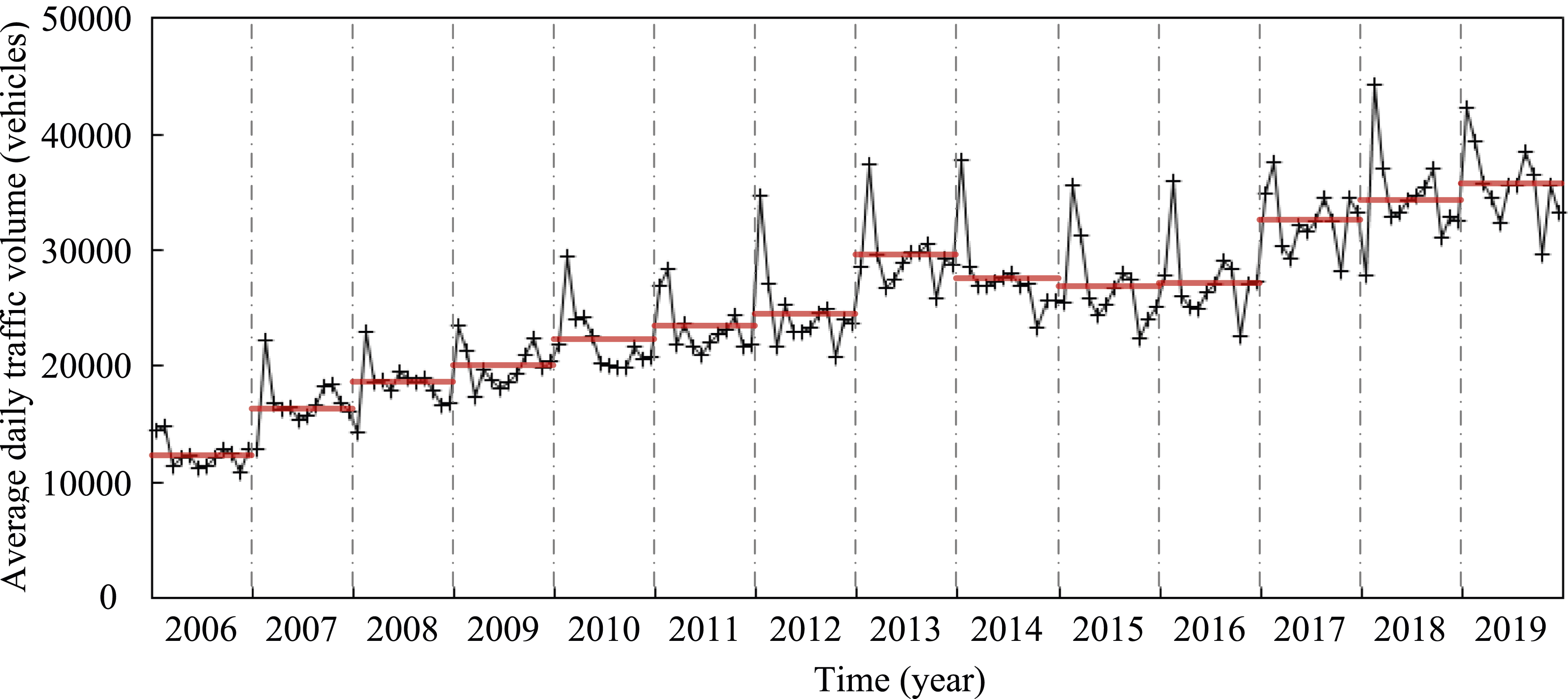
Finite element model
To investigate the service condition of longitudinal steel truss diaphragm, especially the stress at cracking welding holes, and then analyzing the damage mechanisms, a finite element (FE) model need to be built. In view of the commonly used simple beam elements model hard to provide actual stress of structural details, it may not suitable for fatigue analysis (Fan et al., 2020a; Zhong et al., 2016).
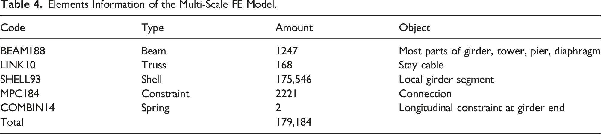
In this study, a multi-scale FE model of the case bridge was developed in two steps (Wang et al., 2019) based on the software platform ANSYS, as shown in Figure 6. To be specific, a global model of the bridge should be firstly established by using beam and truss elements only. The steel box girder, towers, and piers were modeled by BEAM188 elements with six degrees of freedom (DOFs) at each node. The stay cables were modeled by LINK10 elements with three DOFs at each node. The initial material properties, cross section, and other model parameters were determined by bridge design files. The global FE model was subsequently updated using the in-site static and dynamic measurements (i.e., deflection response and modal frequencies) from completion test of the bridge. The stiffness of supports were chosen as the parameters in the process of FE model updating (Xu et al., 2019). A great agreement was achieved for the updated FE model between calculated results and in-site measurements, as shown in Figure 7. According to the bridge design files and related investigation, steel girder segments near the middle of the main span of the bridge can be regarded as the most critical part for fatigue analysis. Hence, shell elements (i.e., the SHELL93 element with six DOFs at each node) with a fine mesh were then adopted to build a local model of 107.5 m long steel girder segments. All components involved in these segments, including top plate, bottom plate, ribs, and diaphragms were presented in detail for the purpose of analyzing fatigue damage. By replacing critical segments in global FE model with the local model, the multi-scale FE model of the case bridge was therefore developed. The DOFs between elements of the multi-scale FE model were connected by using multipoint constraint or sharing common nodes. The free-mesh scheme was adopted for refined local model, the element size around the connection of steel tube and gusset plate was about 1∼5 mm and increased gradually away from the critical region to achieve smooth transition between elements. Thus, a balance would be achieved between computational efficiency and accuracy. There are a total of 179,184 elements in the FE model, including 1247 beam elements, 168 truss elements, 175,546 shell elements, 2221 constraints, and two springs. The elements information of the multi-scale FE model is shown in Table 4. The multi-scale FE model of Nanjing Dashengguan Yangtze River Bridge. The FE model updating results: (a) girder deflection; (b) natural frequency. Elements Information of the Multi-Scale FE Model.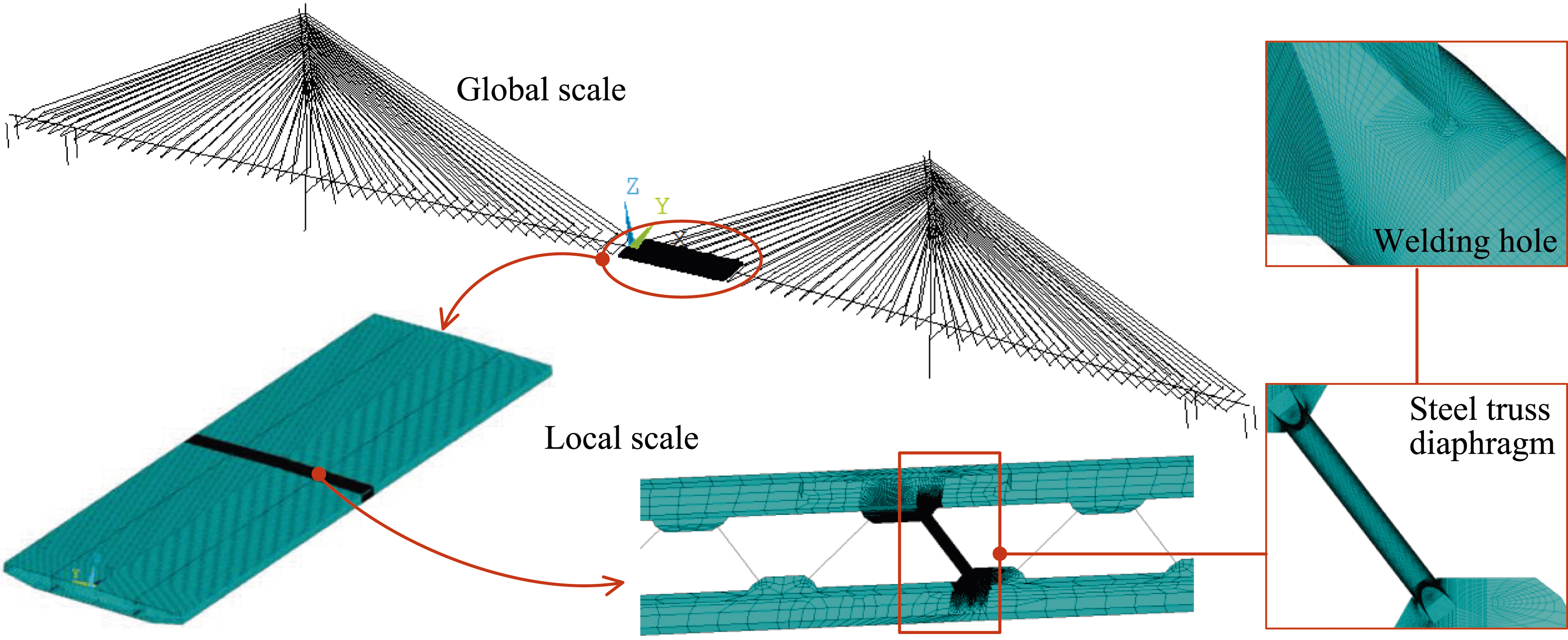

With the established FE model, the unfavorable static design loads were firstly acted to investigate the overall stress distribution and preliminary determine the critical part, seen Figure 8. The girder cross section at a distance of 61.6 m from mid-span was selected to investigate according to static analysis. The stress levels at most regions of a steel tube are very low, which are far less than design values of the Q345D grade steel. However, there exist an obvious local stress concentration around the welding hole. The maximum tensile stress is 179.70 MPa, the maximum compressive stress is 97.35 MPa, and the maximum shear stress is 135.76 MPa. All the stress values meet the design strength under the unfavorable static design loads. In the other words, cracks at longitudinal steel truss diaphragm are not result from the static load. Stress distribution of the steel tube: (a) overall view; (b) close-up view of local region.
Fatigue life estimation
Then, following the above fatigue analysis procedure, fatigue life of longitudinal steel truss diaphragm in the NDYB was estimated. The fatigue life of components can be defined as the minimum of the calculated fatigue lives at these determined critical parts. The standard BS 5400 Part 10 provide the fatigue detail classes and corresponding constant term parameters for different steel structural members. The detail class of critical part in longitudinal steel truss diaphragm are determined as type C, whose corresponding parameters in equation (2) are m = 3.5 and K2 = 4.23 × 10¹³. Meanwhile, the constant amplitude non-propagating stress range value The longitudinal stress influence lines of the critical detail.
By applying the fatigue vehicle loads to the influence line obtained from the FE model, the stress time history at the critical detail of potential cracking was calculated. Only one vehicle was applied to the FE model for one time. Then, the fatigue stress range spectrum for one million traffic volume was obtained using the rainflow counting method, as shown in Figure 10. Most stress cycles are lower than that constant amplitude non-propagating stress range Fatigue stress range spectrum of the critical detail.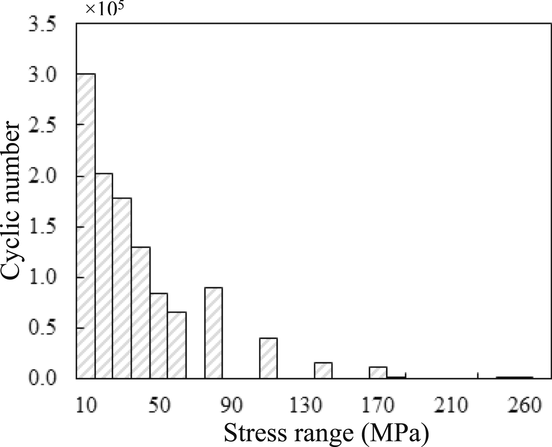
Strengthening measure and assessment
Refer to previous experience, most cracked steel components can be repaired or replaced. However, some strengthening measures gain poor effectiveness due to the lack of investigation. Considering the complexity and diversity of fatigue cracking in steel girder, there is currently no an universal maintenance and strengthening method. In view of previous used crack-stop holes failed to prevent the propagation of cracks, the bridge management department made plans in 2013 to gradually replace the diagonal tube with channel steel, refer to related experience from the Runyang Bridge and the 2nd Nanjing Yangzi Bridge (Guo et al. 2015, 2016), as shown in Figure 11. Every two channel steels are placed back-to-back, and then bolted onto the gusset plates. Two types of channel steel were considered, which in this paper were named as the C-200 (200 mm height, 75 mm width, 9 mm thickness) and the C-180 (180 mm height, 70 mm width, 9 mm thickness), respectively. The proposed strengthening measure.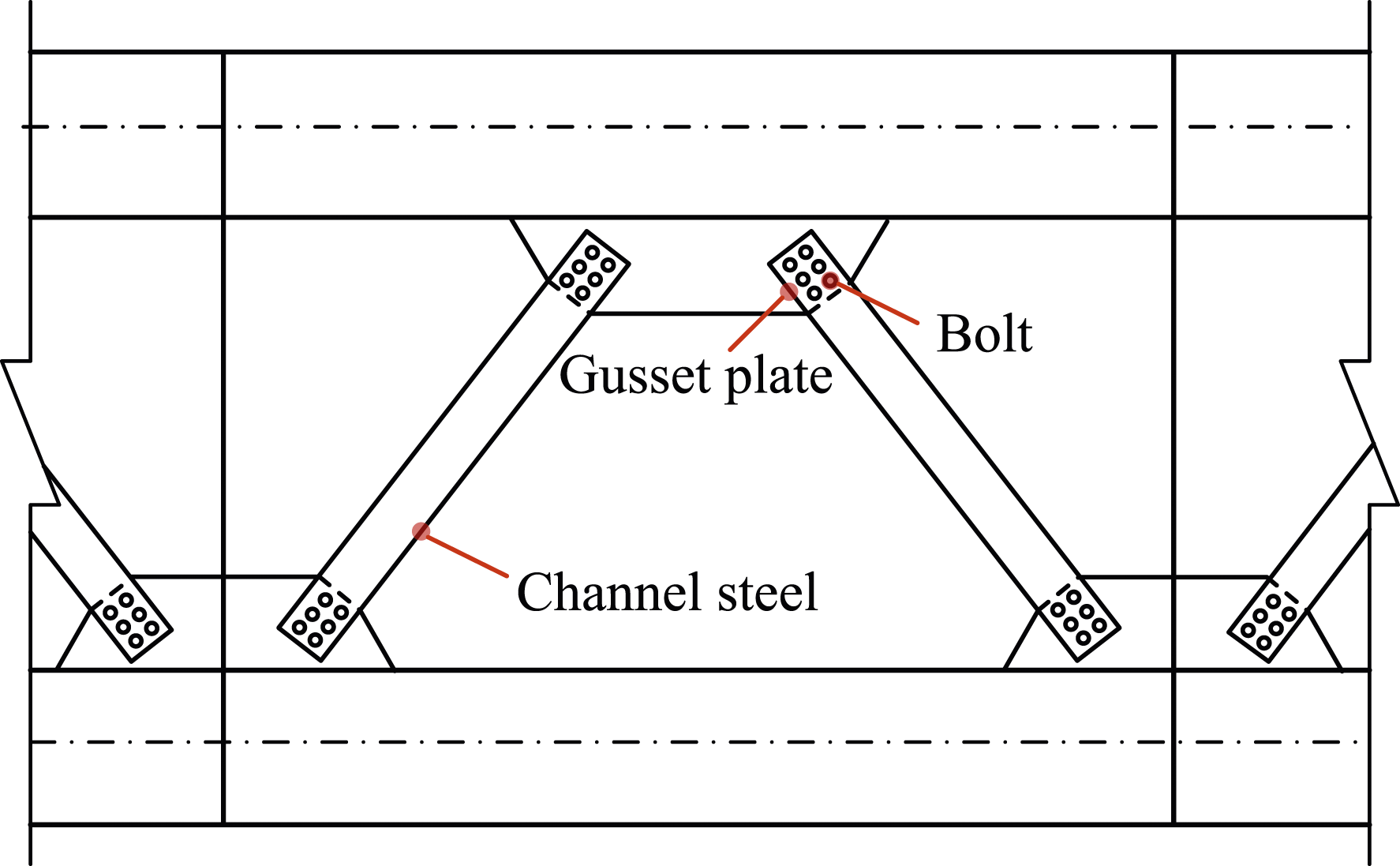
In order to provide a quantitative assessment on the performance of different strengthening measures, the same analysis procedure was used to estimate the fatigue life. Local FE models of channel steels were established and replaced the former steel tubes. The critical part of strengthening longitudinal steel truss diaphragm can be determine from stress distribution under unfavorable static design loads, as shown in Figure 12. The stress level of channel steels is very low (ranges from 10 to 20 MPa for C-200 and 15∼25 for C-180), although local stress concentration is still existed near the connection of channel steel and gusset plate. The stress condition has been improved compared with the original structure. For the C-200, the maximum tensile stress is 89.34 MPa, and the maximum shear stress is 46.86 MPa. As for the C-180, the maximum tensile stress is 165.93 MPa, and the maximum shear stress is 60.75 MPa. All the stress values meet the design strength of the Q345D grade steel. In addition, the detail class of critical part in strengthening longitudinal steel truss diaphragm are determined as type C according to standard BS 5400. The longitudinal stress influence lines of critical details of the strengthening steel truss diaphragm at most unfavorable cross section can be obtained as shown in Figure 13. Local models and stress distributions of steel truss diaphragm after replacement: (a) stress distribution of the C-200; (b) stress distribution of the C-180. The longitudinal stress influence lines of the critical details: (a) overall view; (b) close-up view of local region.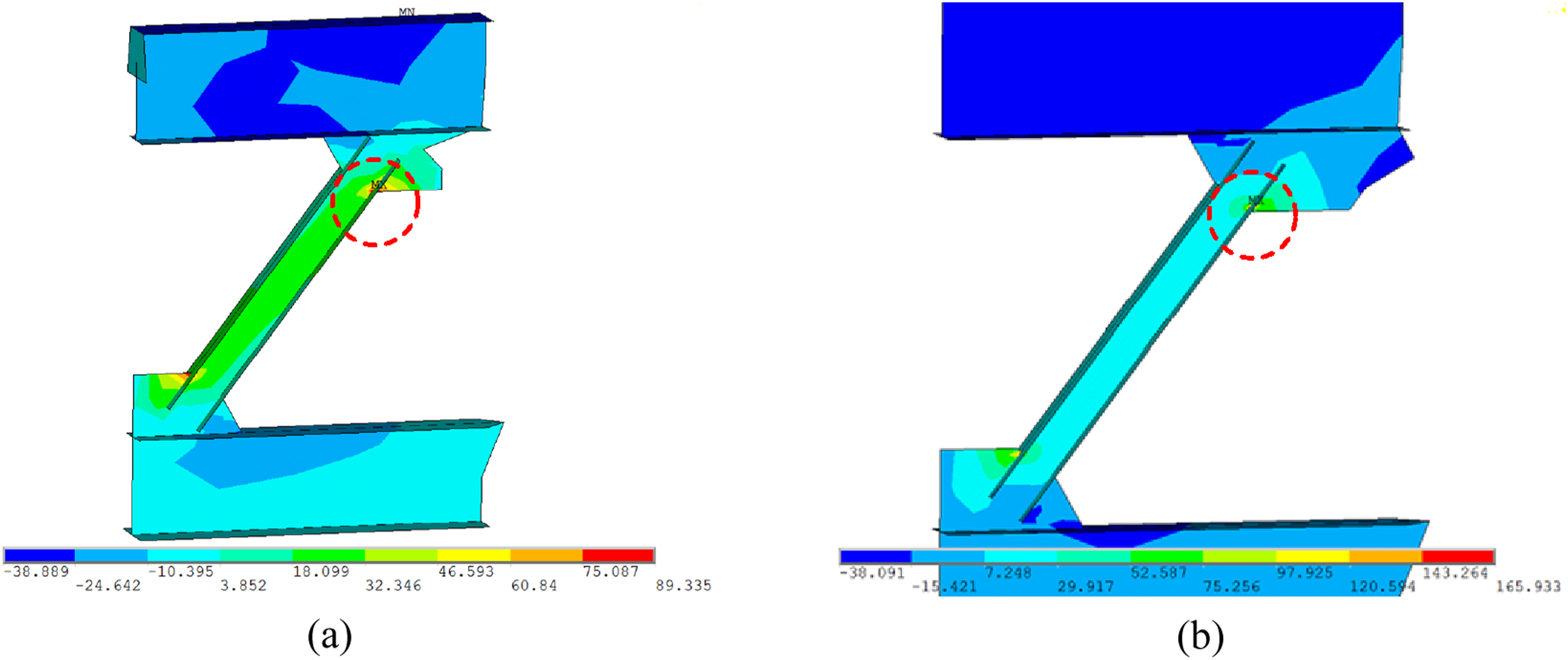
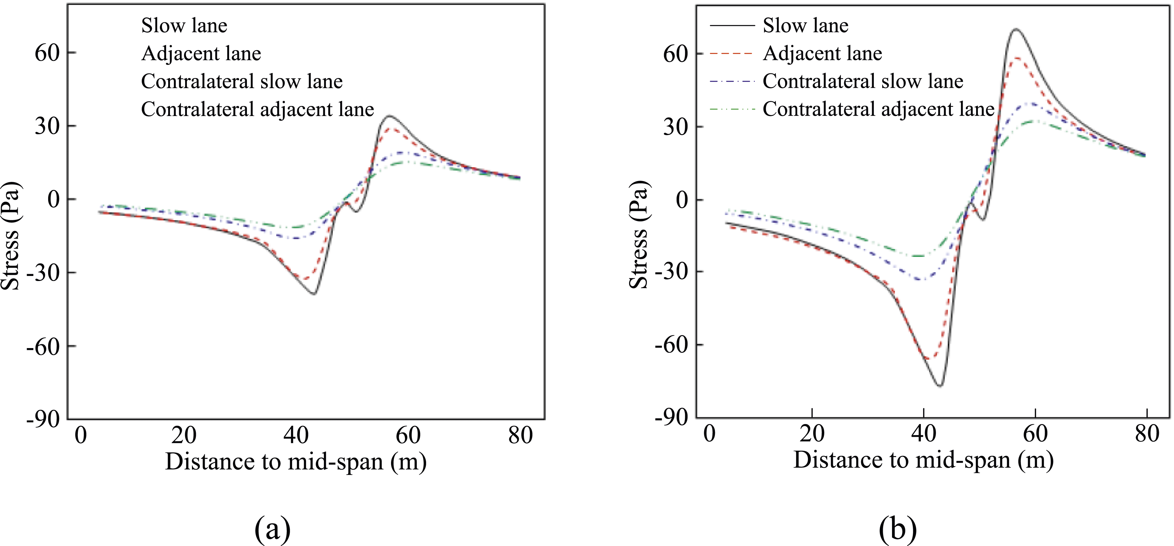
Then, following the fatigue analysis procedure, the stress time history at the critical detail of strengthening structures were analyzed. Using the rainflow counting method, the fatigue stress range spectrums for one million traffic volume can be obtained, as shown in Figure 14. All these two strengthening measures will significantly reduce the stress ranges compared with the original structure. The Miner’s summations Fatigue stress range spectrum of the critical details of strengthening structure: (a) replaced with the C-200; (b) replaced with the C-180.
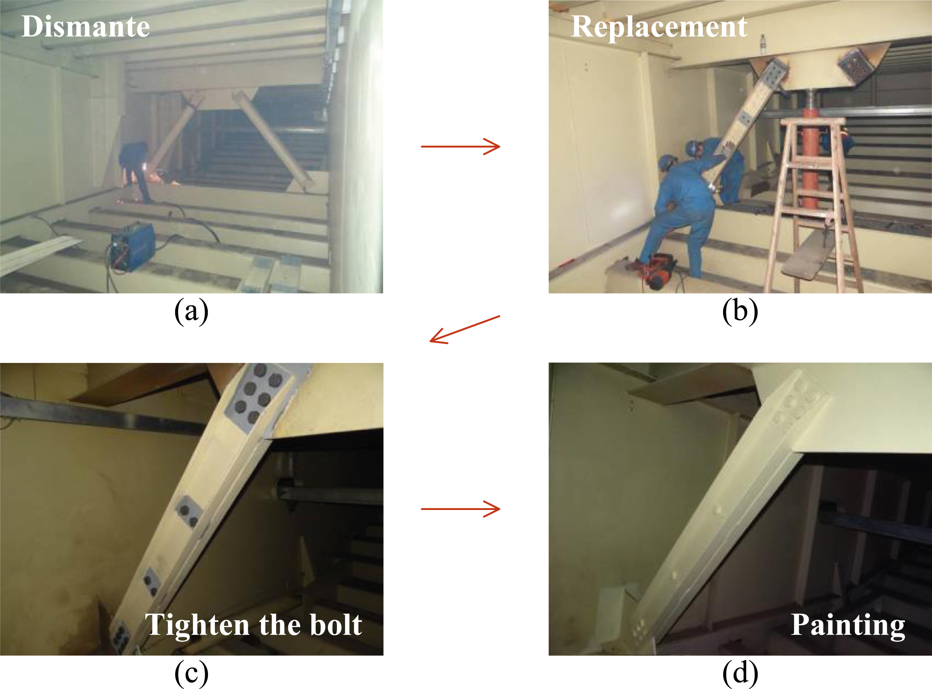
Referring to assessment results, the bridge management department finally decided to replace the former steel tube with the C-200. The construction site of strengthening is shown in Figure 15. The operational process of the adopted strengthening measure can be summarized as following: • Dismantling steel tubes: Cut the cracking steel tubes with carbon arc air gouging method. Temporary support should be installed to bear external loads. • Polishing and drilling: Use a grinder to smooth the cutting point of the longitudinal steel truss diaphragm. Then, drill bolt holes on the gusset plate and treat the friction surface. • Replacement of channel steel: Place two channel steels back-to-back, and install in the specific location. Tighten the bolts to fix the members. • Painting: Paint the strengthening components and repair other breakages of longitudinal steel truss diaphragm. Operational process of the strengthening measure in Nanjing Dashengguan Yangtze River Bridge.
After the channel steels were adopted and gradually replaced the former steel tubes in 2014, it worked very well and fatigue cracks in longitudinal steel truss diaphragm had no longer been further found by now. That indicate the used strengthening measure achieves good effects. It can also provide experience and reference for maintenance of similar structures.
Conclusions
This paper presents the whole process of fatigue analysis for longitudinal steel truss diaphragm in a cable-stayed bridge based on field investigation and FE model. The fatigue life is estimated and effective strengthening measure is conducted to mitigate cracking. The following conclusions can be drawn from this paper: (1) To reduce the structural weight, longitudinal steel truss diaphragms were used in NDYB. However, fatigue cracks near the connected gusset plates were widely observed, the length of them ranged from 5 to 600 mm, which greatly threatened the safety of bridge. Hence, effective measures were needed for maintenance. (2) The Miner’s damage accumulation based method was proved to be an appropriate method for fatigue analysis of longitudinal steel truss diaphragm. The recorded traffic data and a multi-scale FE model should be involved to determine actual fatigue vehicle models and the critical detail, stress time history can also be simulated. According to analysis results, there is an obvious local stress concentration around the welding hole. (3) According to the analysis results, the fatigue life of critical detail of longitudinal steel truss diaphragm in the NDYB was approximately estimated to be only 2.7 years from the bridge opened to traffic, which was far shorter than service life of the bridge. The analysis agrees well with the actual field inspected cracking phenomena. (4) For existing steel truss diaphragms with fatigue cracks in the NDYB, an acceptable strengthening measure that replaces former diagonal steel tubes with steel channels was proposed. According to the field observation and fatigue assessment, no cracks were found since replacement and the estimated fatigue lives of improved members were about 196 years.
Footnotes
Declaration of conflicting interests
The author(s) declared no potential conflicts of interest with respect to the research, authorship, and/or publication of this article.
Funding
The author(s) disclosed receipt of the following financial support for the research, authorship, and/or publication of this article: This work was supported by the National Key Research and Development Program of China (No. 2022YFB3706704), the Academician Special Science Research Project of CCCC (No. YSZX-03-2021-01-B, and YSZX-03-2022-01-B), the Science Foundation of Zhejiang Sci-Tech University (No. 22052331-Y), and General Science Research Project of Department of Education of Zhejiang Province (No. Y202354008).