
Abstract
GFRP was employed in constructions as an alternative to steel, which has many advantages like lightweight, large tensile strength and resist corrosion. Existing researches are insufficient in studying the influence of hybrid reinforced concrete composite columns encased by GFRP I-section (RCCCEG) and I-section steel (RCCCES). In this study twenty one (RC) specimens of a cross-section of 130 mm × 160 mm, with different length (long 1600 mm and short 750 mm) were encased by using I-section (steel and GFRP) and tested under various loading (concentric, eccentric and flexural loads). The test was focused on the influence of many parameters; load-carrying capacity, mode of failure, deformation and drawing an interaction diagram (N-M) for columns. The research explores the feasibility and effectiveness of the employing GFRP and steel sections. The test results concluded that all the composite columns with I-section steel presented similar failure modes to I-section GFRP composite column. Increasing in strength and ductility in short and slender reinforced concrete composite columns related to reinforced concrete columns. The eccentric load has a significant reduction in column strength, especially in slender column. The 3D FE models of (RCCC) were established by ABAQUS. (RCCC) was studied in terms of failure mode, deformation and bearing capacity also an analytical study was employed to obtain analytical results for short specimens subjected to flexural load and employing these outcomes for drawing interaction diagram (N-M) for short columns. Based on the verification of FE analysis, the experimental and theoretical results showed a good agreement.
Introduction
Because of the rapid development of civilization and increase civilian population, high-rise structures and long cross sections are employed in construction of tall structures; composite columns are considered as ideal alternatives to RCC with large cross section due to the lower cost and self-weight, establish excessive building space and easily constructed, so employing sections of (steel and GFRP) for improving the durability and sustainability of columns. The load capacity of RCC decrease due to premature failure appeared and deterioration in the steel properties like corrosion so it replaced by GFRP as a protection element and considered alternative solution in the humid environment locations due to corrosion resistance, large electromagnetic resistance and low density compared to steel reinforcement (Correia et al., 2013; ACI-440.2R-17, 2017; Zadeh and Nanni, 2013). This chose in humid environments to decrease the maintenance costs and improve concrete serviceability (Ibrahim and Allawi, 2023; Ibrahim et al., 2023; Mohammed and Said, 2024). The using of GFRP as partially or completely replacement for reinforcing steel counterparts in structural element considers an effective way to enhance the structure durability by minimizing corrosion of steel. Reinforced concrete structures should behave ductile to exclude collapse in the structures, at the same time; columns should have adequate ductility to tolerate an axial and eccentric load at the post-peak region. Extensive investigations have been recently conducted to search the structural performance of GFRP bar and sections. Due to the extremely conservative requirements of the code and the shortage of standard guidelines in the concerning of the concrete columns with GFRP, which necessary additional experimental and analytical research in this field to duly present the performance of the concrete columns. Investigate an experimental test by using columns reinforced by steel bars and GFRP bars. This study appeared that increasing in column capacity and improving ductility in column reinforced with steel bar when compared with column reinforced with GFRP bars (Hadi and Youssef, 2016). Composite columns are established by combining various components material with good mechanical properties. The article mentioned that it is better to replacement steel bars with GFRP bars in foundations exposed to corrosion and loads (Teng et al., 2007). The influence of utilizing steel in combination of with other materials such as concrete can ameliorate the behavior and cost of columns employed in the constructions, related to using steel columns only (Begum, 2007). Findings show that polypropylene fiber (PF) achieves improvement in ductility, tensile and flexural strength for plain concrete. Additionally confirm that PF enhances the effect of GFRP bars and increasing column capacity and ductility (Ahmad et al., 2024). The behavior of reinforced concrete (RC) columns with fiber-reinforced polymer (FRP) reinforcement differs from that of columns with steel reinforcement. In FRP-reinforced columns, the load-carrying capacity increases under eccentric tension compared to eccentric compression. Additionally, the point of failure in FRP-reinforced columns tends to occur under eccentric tension. The interaction diagram for FRP-reinforced columns exhibits a concave shape in a specific segment (Korentz and Czarnecki, 2023). Special-shape of RC composite columns encased with GFRP core were tested under axial load, which found that stress in concrete elements were decreased from the center to the verges due to the effect of restraint, which was lower on the circumferential concrete than on the concrete core (Ji et al., 2022). The influence of EGCSSCs subjected to axial load was affected by many parameters and influenced by the interaction between these parameters (Hadi et al., 2017). Preceded an experimental study for column reinforced by steel tubes instead to steel bars and used self-compacted concrete, the results appeared that strength of columns reinforced with steel tubes have a good agreement related to columns reinforced with steel bars and ductility increased when column subjected to concentric load (Alhussainy et al., 2018). From the literature reviews realizing that there are few researches have discussed the behavior of composite RC column encased with I–section steel and GFRP in terms of load capacity and deformation by using experimental and analytical methods. For this, more researches are needed to perfectly understand the behavior of these types of composite columns. As indicated above, the aim of this study is to discuss and recognize the behavior of hybrid column encased with I-section GFRP and composite columns encased by I-section steel compared with reinforced concrete columns (control column) with different length(short and long) under verity load conditions, due to, limited knowledge about adaptability of these types of composite columns exists. It also aims to draw the interaction diagrams for all specimens, at the same time an analytical study was used to estimate the behavior of short specimens under flexural load and employ these analytical results for drawing N-M diagrams for short columns. Validation of the experimental results adopted by using FE analysis performed with ABAQUS software.
Experimental work
Testing specimens
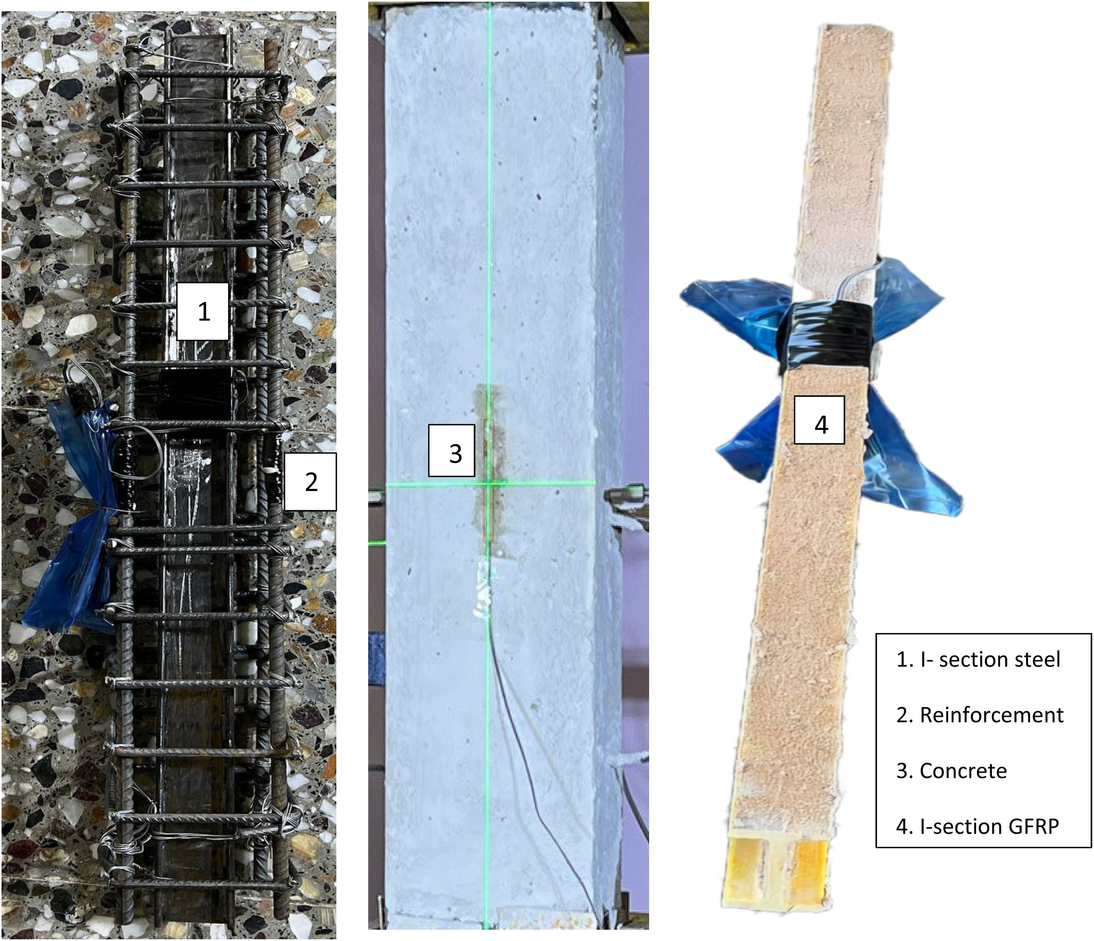
Twenty-one rectangular RC columns of mid-scale dimensions were casted and tested under various loading conditions (concentric, eccentric, and flexural loading). All specimens have cross-sectional dimensions of 130 mm × 160 mm with different height 750 mm and 1600 mm. The specimens portioned into two sets depended on column height (short and long); the height of the short column 750 mm and the long 1600 mm which specified according to ACI318-19 code limitations (ACI 318-19, 2019), all sets contain three groups. First group in each set refer to the reference specimens; reinforced concrete column (RCC), second groups refer to composite column encased with steel I-section (CCES) while third group refer to composite column encased with GFRP I-section (CCEG). Whole specimens were reinforced by four longitudinal steel bars with diameter 10 mm and 6 mm for lateral reinforcement bars with spacing of 50 mm c/c. I-section (steel and GFRP) was located at the center of the column in all the specimens and have similar dimensions cross section as appeared in the Figure 1. Specimens and I- sections details.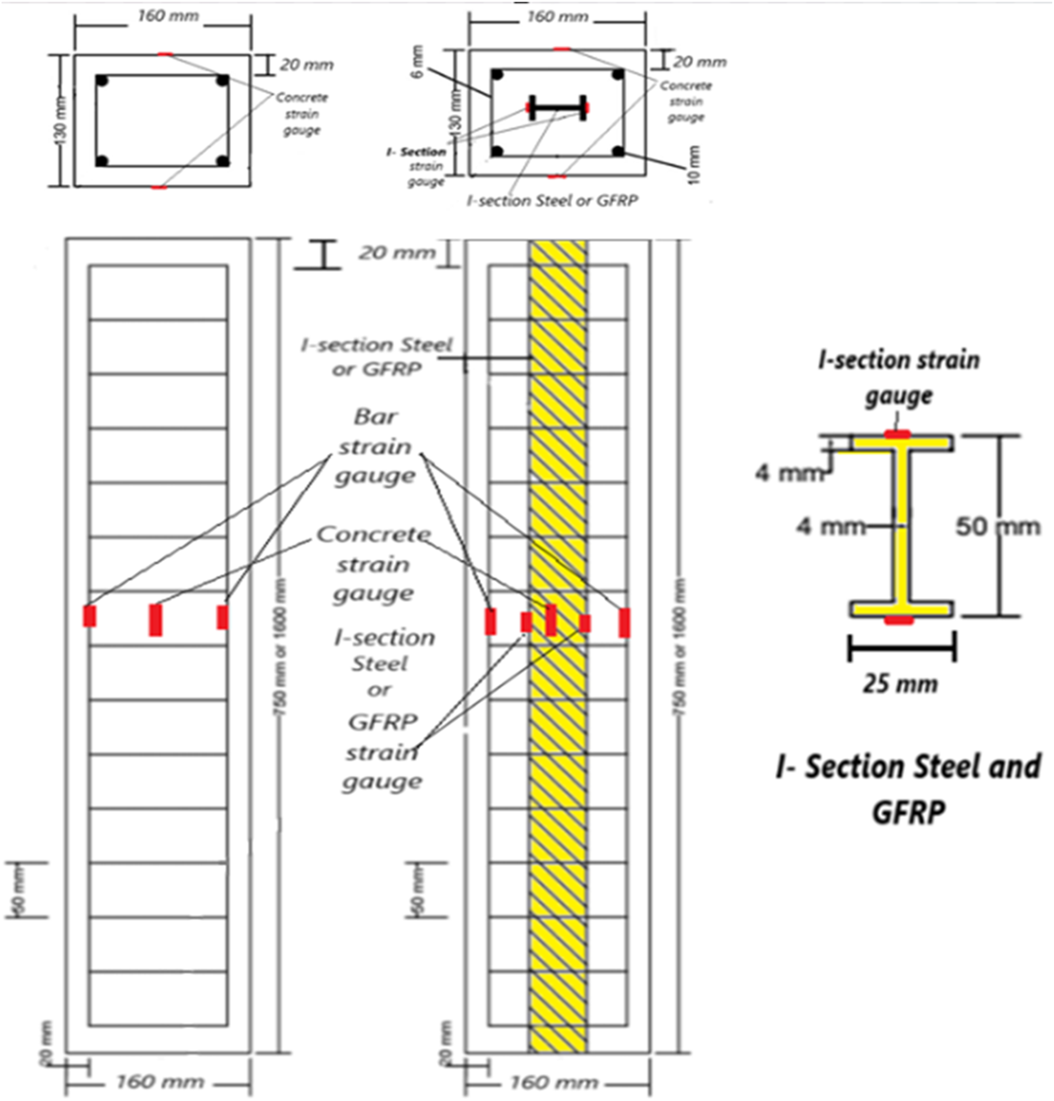
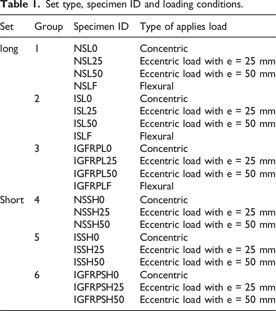
Set type, specimen ID and loading conditions.
Properties of materials
Concrete properties.

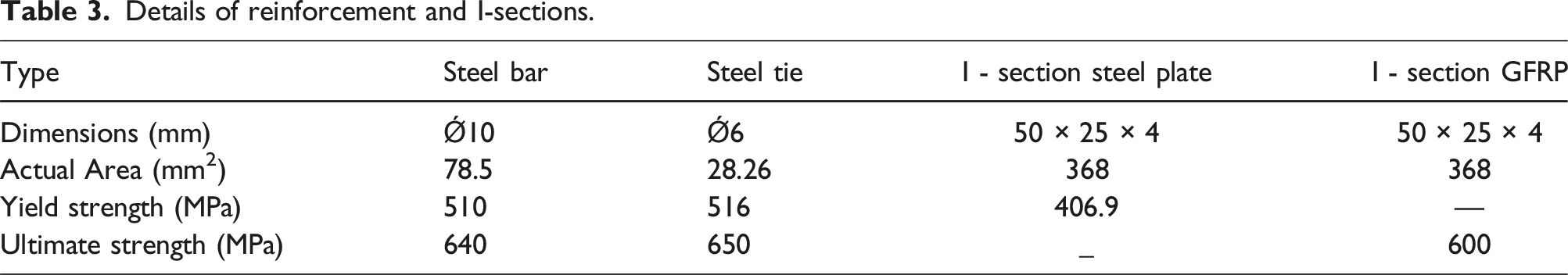
Details of reinforcement and I-sections.
GFRP properties.

Specimens details
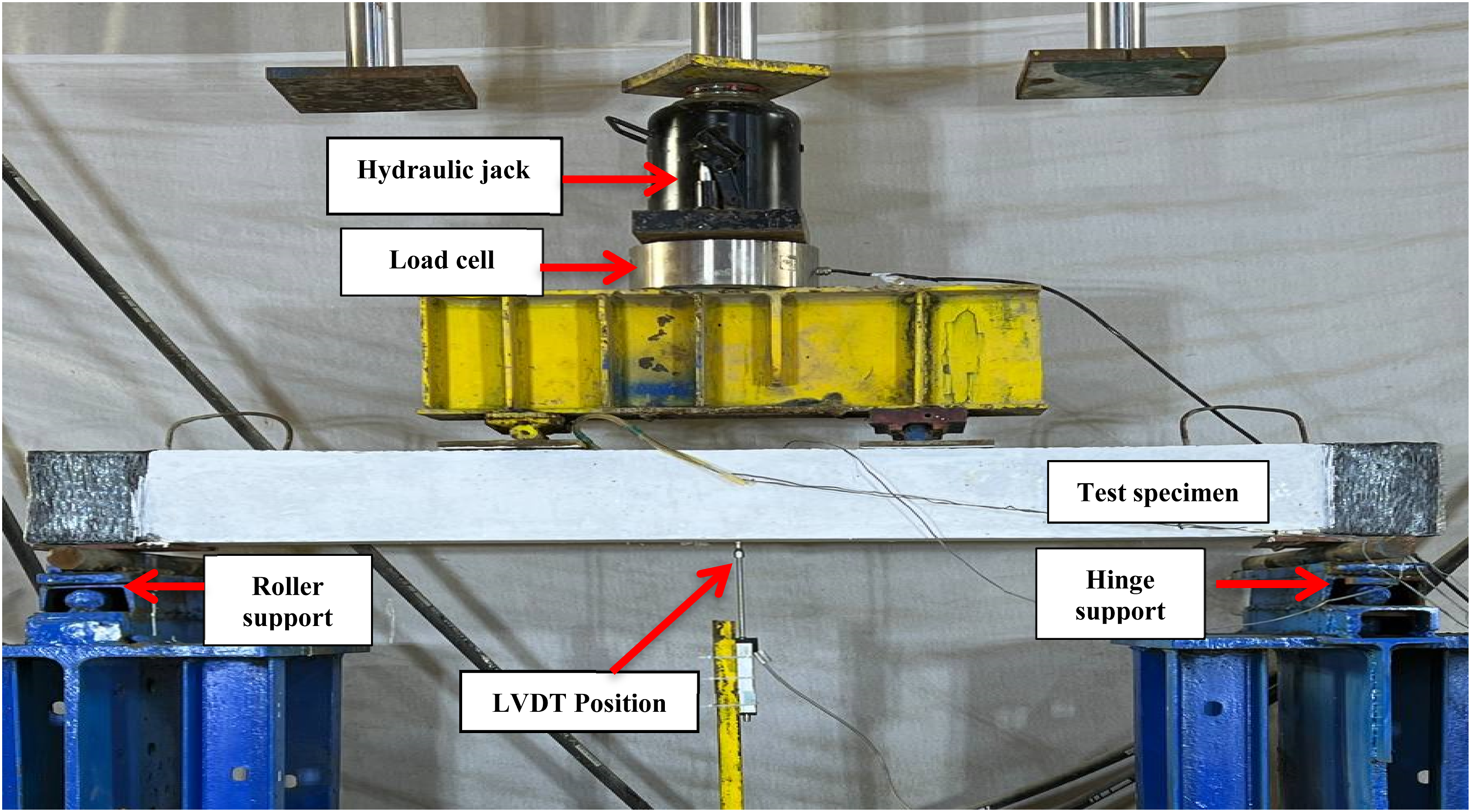
In the experimental test; column support at the top and the bottom ends with hinge which manufacturing from steel as a cap used for applying axial load (concentric and eccentric). At the same time four saddles were made from steel were used in the flexural test, as represented in Figures 2 and 3. A hydraulic rig was used with a maximum capacity of 200 ton for testing column. To avoid concrete crushing, CFRP sheet was utilized with 150 mm width for strengthening two ends of long column and 100 mm width for strengthening short column. At the same time installing load cell with capacity of a 200 ton between the cap and hydraulic jack for measuring load. For measuring axial strain in concrete, longitudinal steel bars and I-section steel and GFRP; two strain gauges were employed at the mid height of the concrete, reinforcement and I-section (steel and GFRP) respectively (Figure 4). Additionally, four linear variable differential transformers (LVDTs) were utilized, two for recording lateral deformation were positioned at the left and right side at column mid height and the remainder were used for recording the axial deformation were positioned at top and bottom of the column. The beam was tested under two-point loads by utilizing a hydraulic jack with capacity of 50 ton and a 100 ton load cell, while deflection was measured at the middle span of the beam by using LVDT located at the bottom of the beam. Load capacity and deformation results were automatically get by employing a computer system. Instrument for the tested column, steel caps and LVDT positions. Instrument for the tested beam and steel saddles. Strain gauge locations.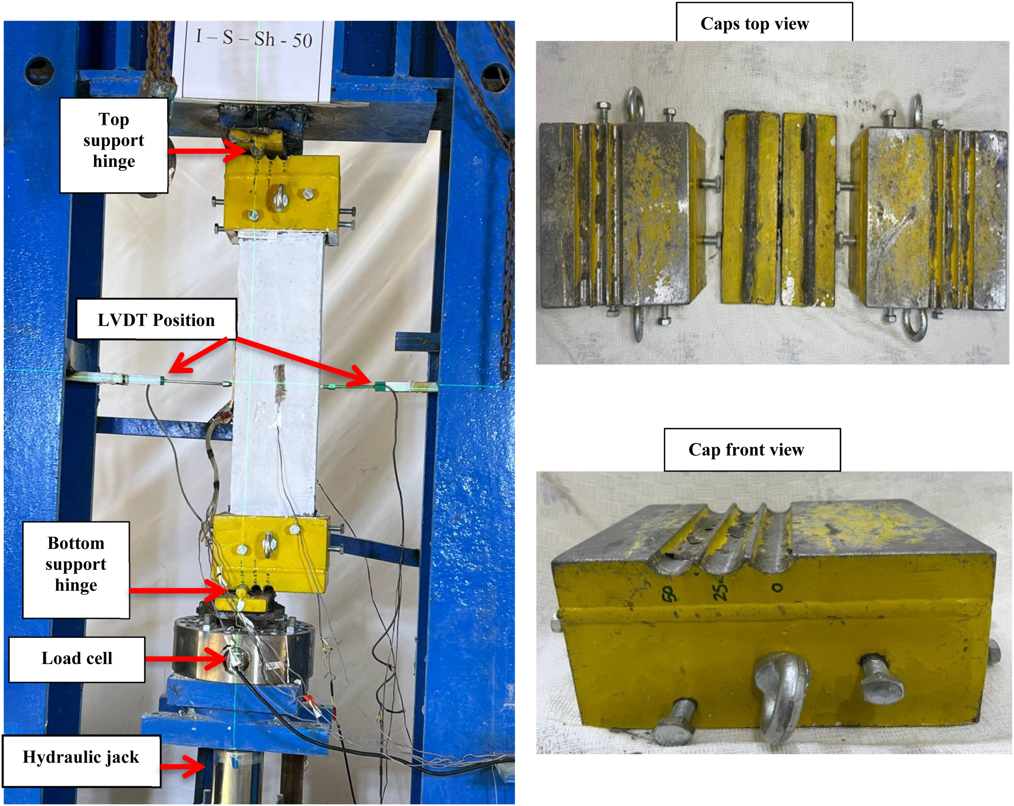
Numerical work
Finite element modeling
The numerical analysis was adopted by using the finite element approach and ABAQUS software (ABAQUS version 6.14, 2019) for modeling the reinforced concrete and encased composite specimen columns and beams. In column analysis; two methods were used nonlinear riks and linear buckle analysis, which were adopted to analyze columns. For both the riks and buckling analysis, all models adopted the same type of elements, geometry and mesh. Explicitly model was adopted for the stirrups modeling by using wire standard truss elements with spacing and interaction them with the concrete by employing solid elements for representing concrete. The interaction bond between stirrups and concrete was done by using embedded region constraints. 900 and 1920 solid elements are used for modeling concrete for short and long specimens respectively adopted by C3D8R elements, 14 and 31 T3D2 elements are used for modeling steel reinforcement for short and long specimens respectively, 8 T3D2 elements are employed for modeling stirrups, also 180 and 384 linear quadrilateral elements of type S4R are used for modeling I- section (steel and GFRP) encased in the short and long specimens respectively, while 120 solid C3D8R elements are used for steel cap for applying load. The stirrups confine concrete due to resist buckling under stress, improving ductility and increase load capacity. Enhancements appear due to the interaction between stirrups and concrete. Many trials are used to select the suitable size of mesh and to obtain closest analytical results. For applying load and boundary conditions (hinge-hinge) supports for the columns during testing by using two steel caps for this purpose. The upper end of the column was restricted by the cap in the x, y and z directions, while the lower end of the column was restricted in x and z directions and movement was allowed in y direction for applying displacement. The beams were tested as a simply supported by utilized four steel plates as saddles, one of the beam supports; hinge and the other roller. Load was applied in two points by displacement control. The finite element conditions and load application are shown in the Figure 5. FE analysis for the Specimens, loading applications and supports boundary condition.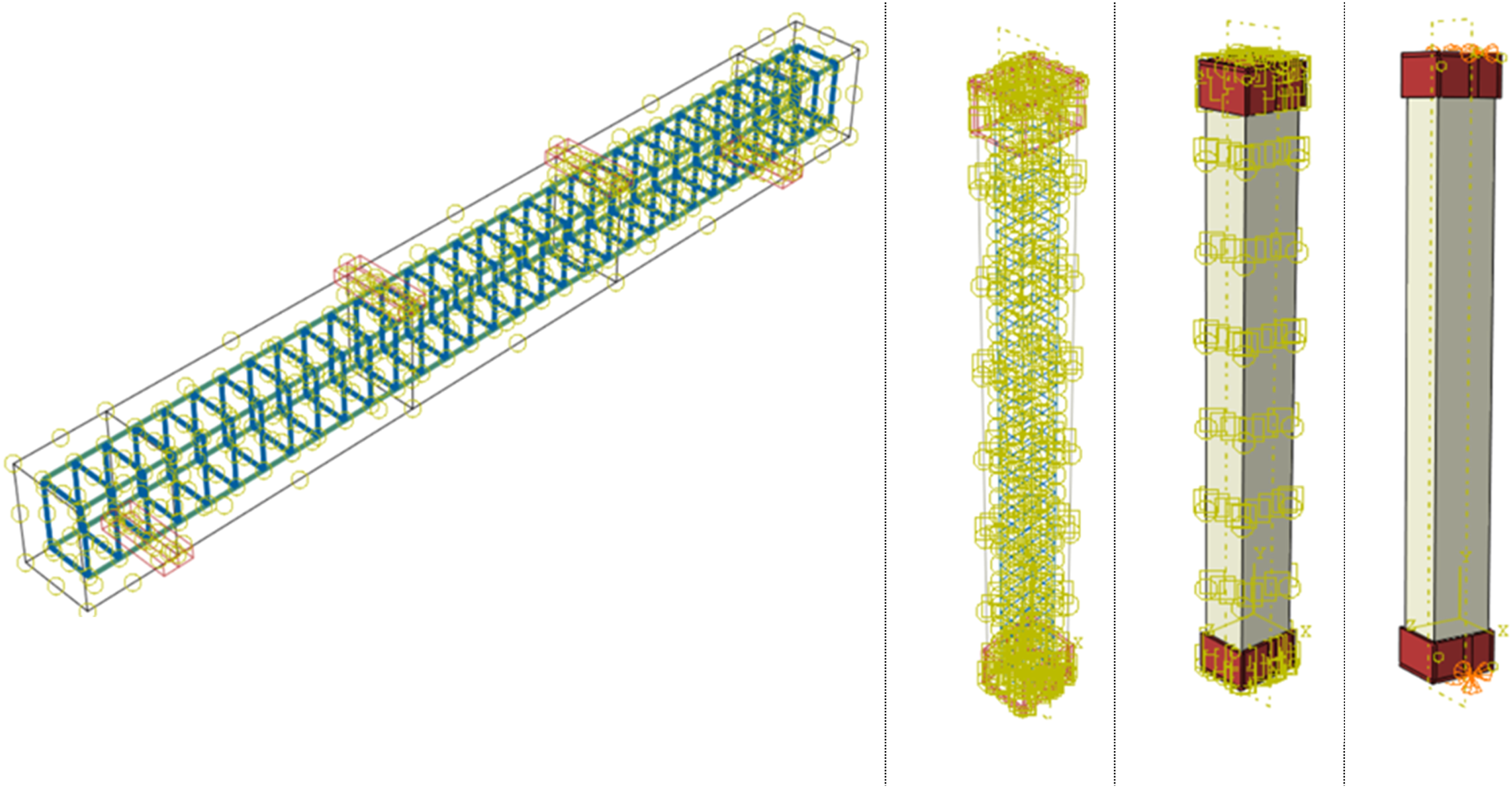
Materials modeling
In concrete to simulate the damage and nonlinear behavior, concrete damage plasticity (CDP) model was adopted in the software (ABAQUS Analysis User’s Manual, 2019), which used for modeling nonlinearity of concrete under different load conditions, involving cracking in tension and crushing in compression. For employing the CDP model effectively, a group of material parameters were used like dilation Angle (ψ) assimilate the angle of the plastic potential surface which domain in concrete from 30° to 40°, flow potential eccentricity (ε) determine the style of the plastic potential function with rate 0.1, ratio of biaxial to uniaxial compressive strength (σb/σc) which related to 1.16 in normal concrete, (Kc) range between 0.65 and 0.8 and viscosity parameter (μ) were employed in analytical model. These parameters are interdependent and value depended on experimental results. Cracking and crushing mechanism in concrete utilizes by stress–strain compression model for concrete (Elwi and Murray, 1979). Elastic perfectly plastic modeling was adopted in longitudinal, transverse reinforcement and steel plate used for manufacturing I-section steel (Ramberg and Osgood, 1943). The bonds between materials lead them to act together for resist loads, enhanced column strength, stiffness, and ductility. The interface between the different materials was modeling by employing embedded region. To determine the interaction nature and the relationship between specimen parts, selected surfaces was done for each part connections. The I-section GFRP was modeled by using the progressive damage model for representing the linear elastic behavior of the undamaged composite materials utilized by (Hashin, 1980; Hashin and Rotem, 1973). Constrain relation was used between I-section steel and I-section GFRP with concrete as embedded region. Interaction contact mechanical was employed between the steel caps and concrete for connection surfaces without separation.
Experimental and FE results and validation
Load carrying capacity
Experimental and FE outcome for ultimate load and deformation.

Effect of encased on the ultimate strength of the short columns (ISSH0) and (IGFRPSH0) under concentric load was improved about 9.4% and 8.8%, respectively, related to control column (NSSH0). Also it improved in the specimens (ISSH25), (IGFRPSH25), (ISSH50) and (IGFRPSH50) when subjected to eccentric load (e = 25 mm and 50 mm) about 11.5%, 10.1%, 20.1% and 13.4% respectively, relative to control columns (NSSH25) and (NSSH50). Figure 6 display the ultimate capacity of the specimens tested under different loads. Long columns (NSL25) and (NSL50) tested under eccentric load with eccentricity 25 mm and 50 mm, achieved about 62% and 34.4%, respectively, compared with the control column (NSL0). Additionally (IGFRPL25), (IGFRPL50), (ISL25) and (ISL50) subjected to (e = 25 mm) and (e = 50 mm) were achieved 65%, 37.9%, 65.2% and 39% respectively, relative to the control specimens (IGFRPL0) and (ISL0) respectively. The study indicates that an enhancement and increasing in columns ultimate strength under concentric load condition due to the column encased I-sections (steel or GFRP) that lead column to became more effective when subjected to load because influence of I-sections for redistribution stress in column that cause to improve column resistance to buckling when subjected to axial load compared with columns have the same cross section subjected to eccentric load. Load capacity for the tested specimens under various load conditions.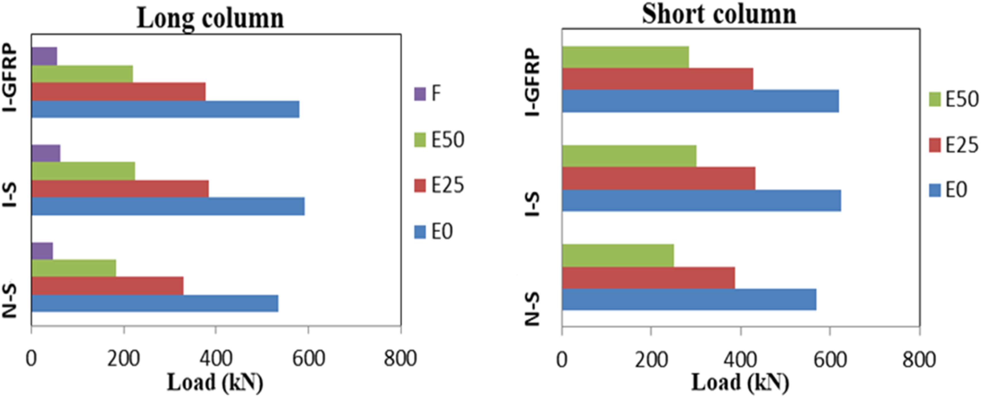
The experimental results in the research show that ultimate strength and deformation significantly affected by the conditions of applied load especially at the eccentric load with e = 50 mm. Whereas the ultimate strength reduce and deformation increase in column due to the effect of bending moment, which create the tension zone that leading to reduce the compression zone. The outcomes of the experimental and FE results show a reasonable accuracy of the ultimate strength and in lateral deformation.
Load and deformation curve
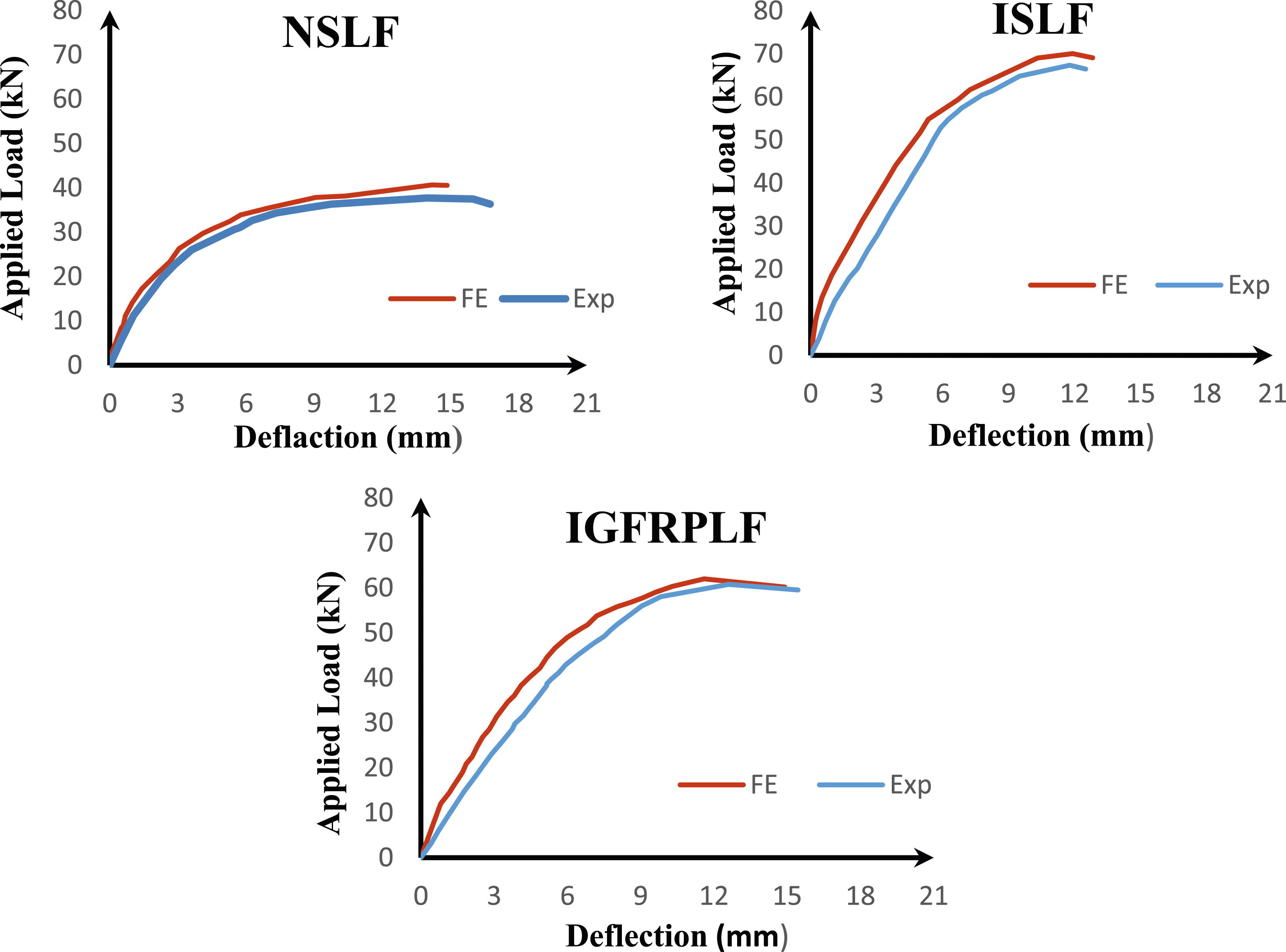
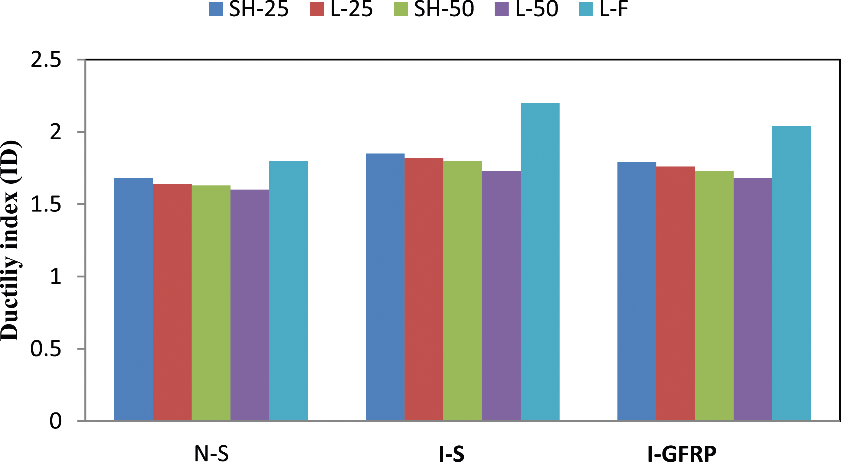
Experimental results appeared that increase deformation in slender columns when compared with deformation of short columns for all conditions of loading. And observe that deformation was slightly increased when applying load increase. Figures 7 and 8 adopted that the experimental and numerical results represented by the FE analysis for long and short reinforced and encased composite columns. For the specimens subjected to flexural load represented by two points load appeared slightly improvement in ultimate load and decrease in deflection when specimens encased with I –section steel and GFRP due to the effect of I-section as utilized in Figure 9. The ductility is a substantial indicator for the member ability to deform beyond the elastic limit. Instituted ductility index (DI) for the eccentric column and beam (Park, 1989). (DI) is defined as the ratio of the deformation accrued at the maximum load ∆u to deformation at the yield point ∆y. In the GFRP ductility index (DI) cannot implementation because of the relationship between stress-strain was linear. Many researchers proposition GFRP (DI), a widely recognized model (Naaman et al., 1995). Figure 10 and Table 6 achieved the ductility index for all tested specimens under eccentric and flexural load. The results show that short columns had significant increase in ductility related to slender columns. The ductility index (DI) improved in the composite encased columns with I-section (steel and GFRP) when compared with the ordinary reinforced concrete columns and show higher ductility under large eccentricity and flexural load conditions due to increase tension area in the encased RC columns and the encased I- sections give more ductility and make column able to resist load and moments also postponement of the appearance of cracks in the concrete, this enhancement was increased for column subjected to eccentric load. Strain was measured in the longitudinal steel bar for all specimens; in both compression and tension through testing under eccentric or flexural loading conditions as shown in Table 6. The results appeared that strain in the compression steel bar was slightly higher than in the tension steel bar and steel bar in tension did not reach the yield stage when tested with 25 mm eccentric load while reached the yield stage under flexural and 50 mm eccentric loads. Load-axial deformation for specimens under concentric axial load. Applied load and lateral deformation for the tested long and short columns under eccentric load (25 and 50 mm). Load-deflection curve for long specimens under two point loads. Ductility index for specimens with various load conditions and encased. Ultimate strain in steel, yield and maximum deformation, and DI for the tested specimens.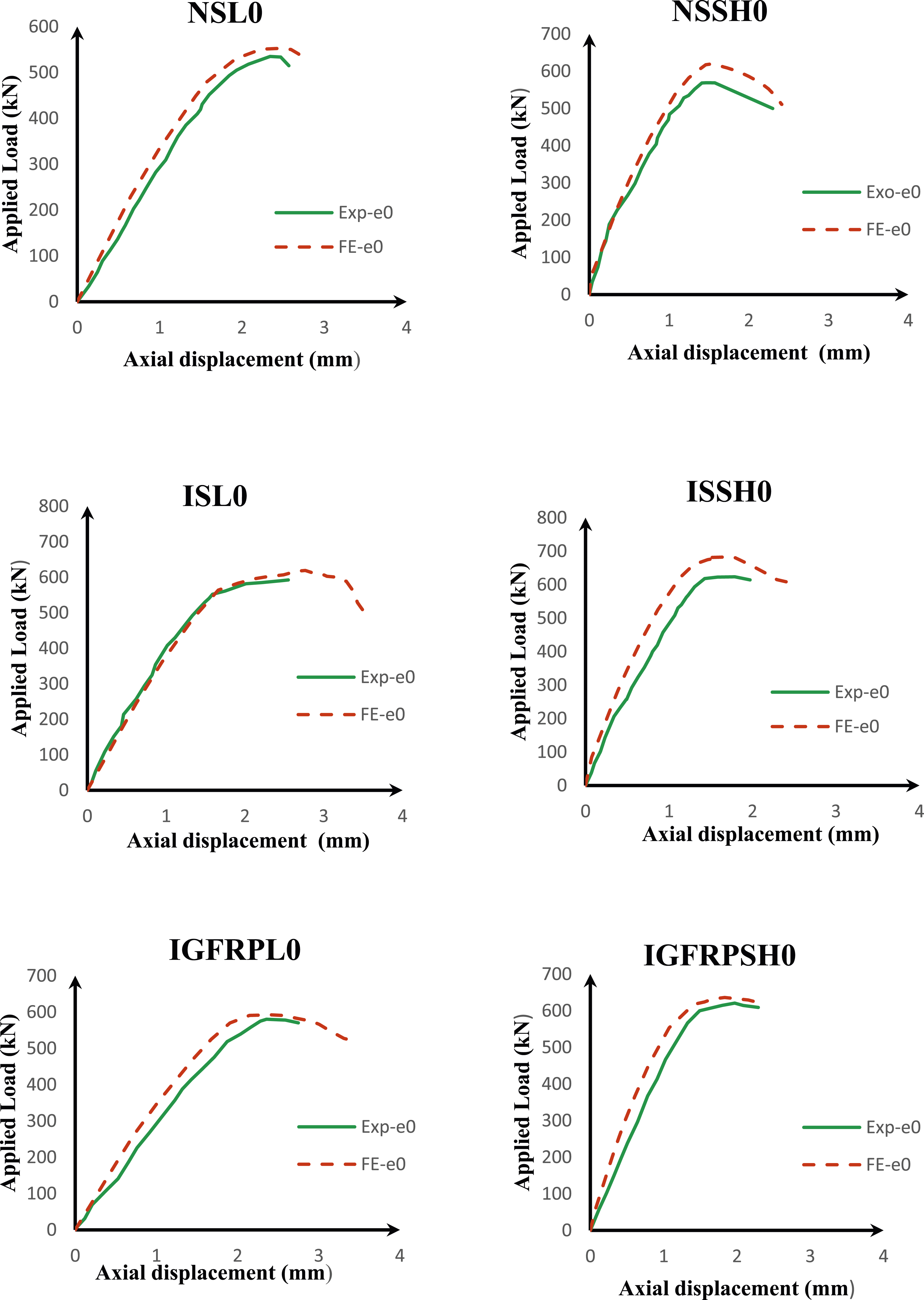
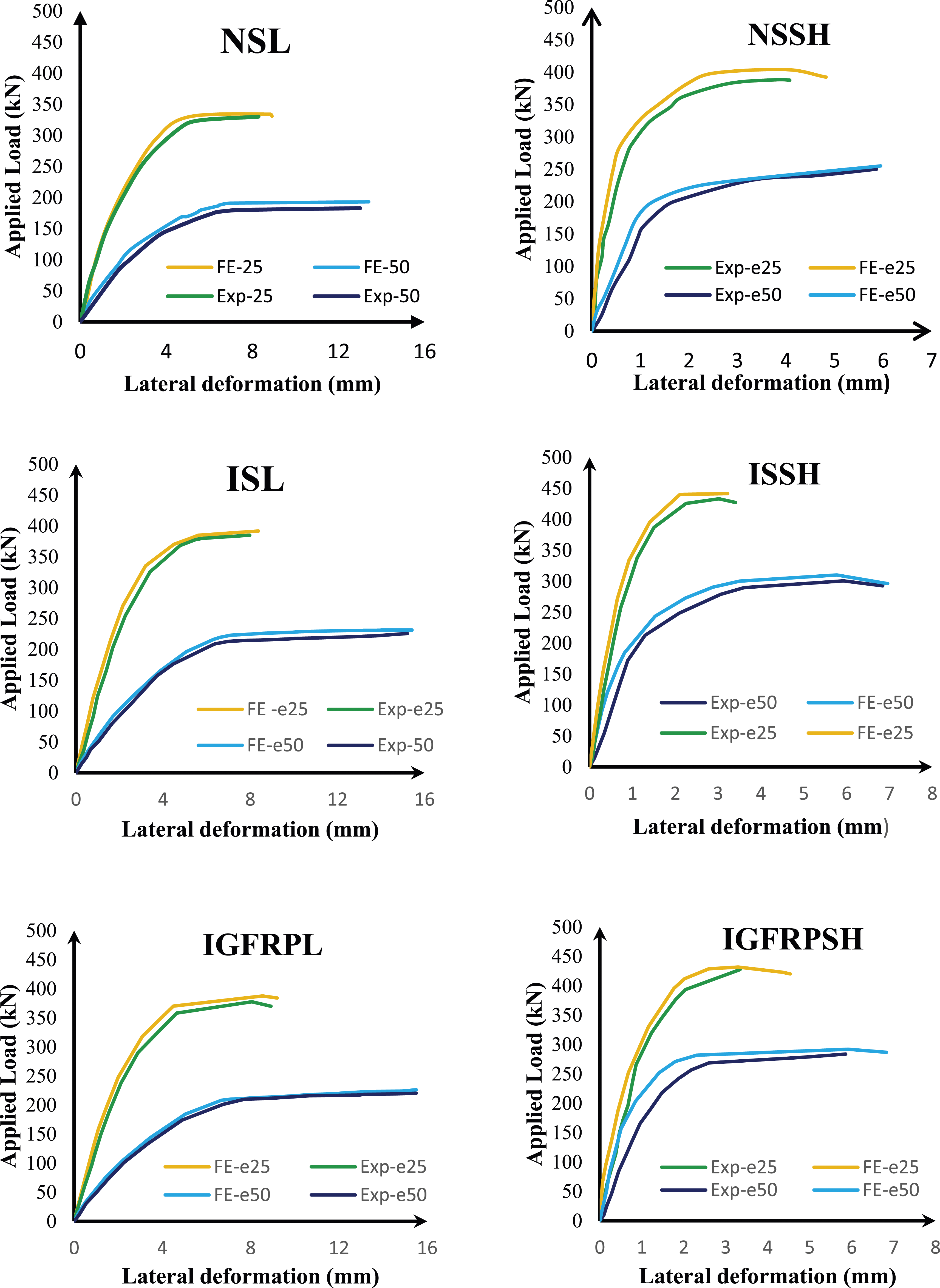
The figures show that the FE results are stiffer than the experimental results due to the assumption of a perfect bond between reinforcement, I- section (steel and GFRP) with concrete, that lead member to behave more rigid. In spite of there are good agreement shown between them in must tested specimens.
Modes of failure for the specimens
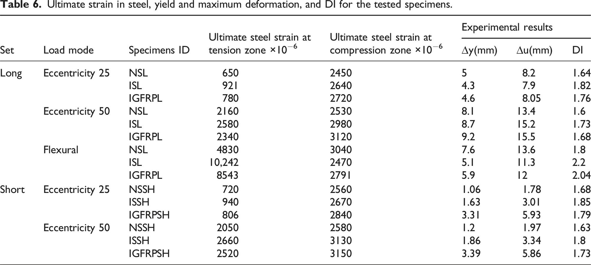
Three failure modes were observed in the tested specimens depending on the column kind (short - slender) and load conditions (eccentric, concentric and flexural). In most short columns and slender columns under concentrated load; compression failure was seen in the middle of the specimens, causing spelling of the concrete cover (Hussein and Said, 2024), as represented in the Figure 11. In the Figures 12 and 13 represented modes of failure for the short and slender columns subjected to axial load with eccentricity 25 mm and 50 mm. In the long columns under 25 mm eccentric load bending failure was appeared due to the effect of eccentricity and the failure mechanism was represented by spelling and crushing of concrete with observation flexural compression failure (Abbood et al., 2024). Tension steel bar and the I-sections (GFRP and steel) do not reach the yield point and no buckling occurred. Additionally reinforcement in the tension zone dose not reaches to the ultimate strain. PEMAG value in analytical model (ABAQUS software) was referred to plastic equivalent strain magnitude that employed in FE analysis to represent plastic deformation. It is a scalar value that accumulates as plastic deformation occurs in a material. Failure mode in experimental and FE analysis for the tested short and long columns under concentric load. Failure mode in experimental and FE analysis of the tested short and long columns under 25 eccentric load. Failure mode in experimental and FE analysis of the tested short and long columns under 50 eccentric load.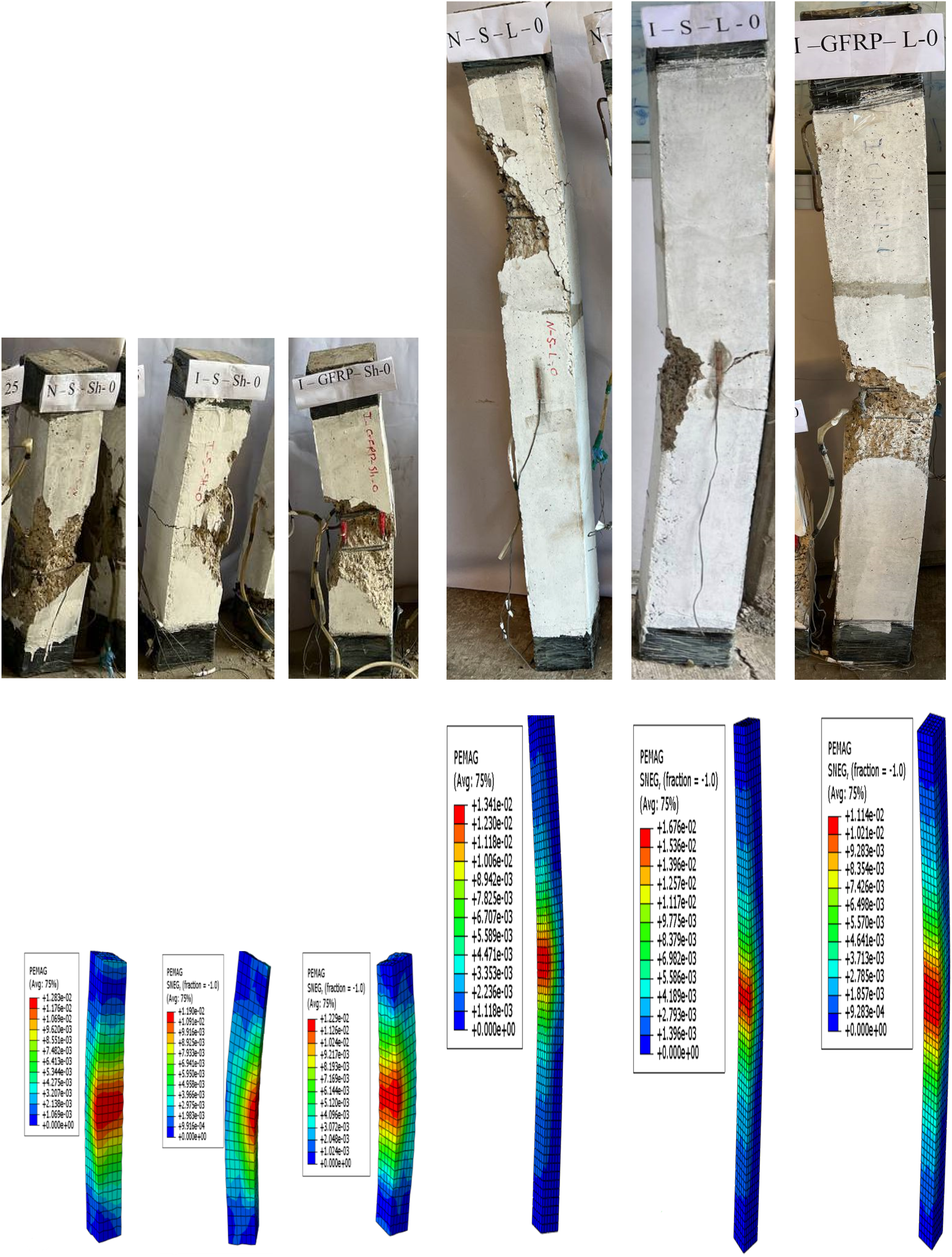
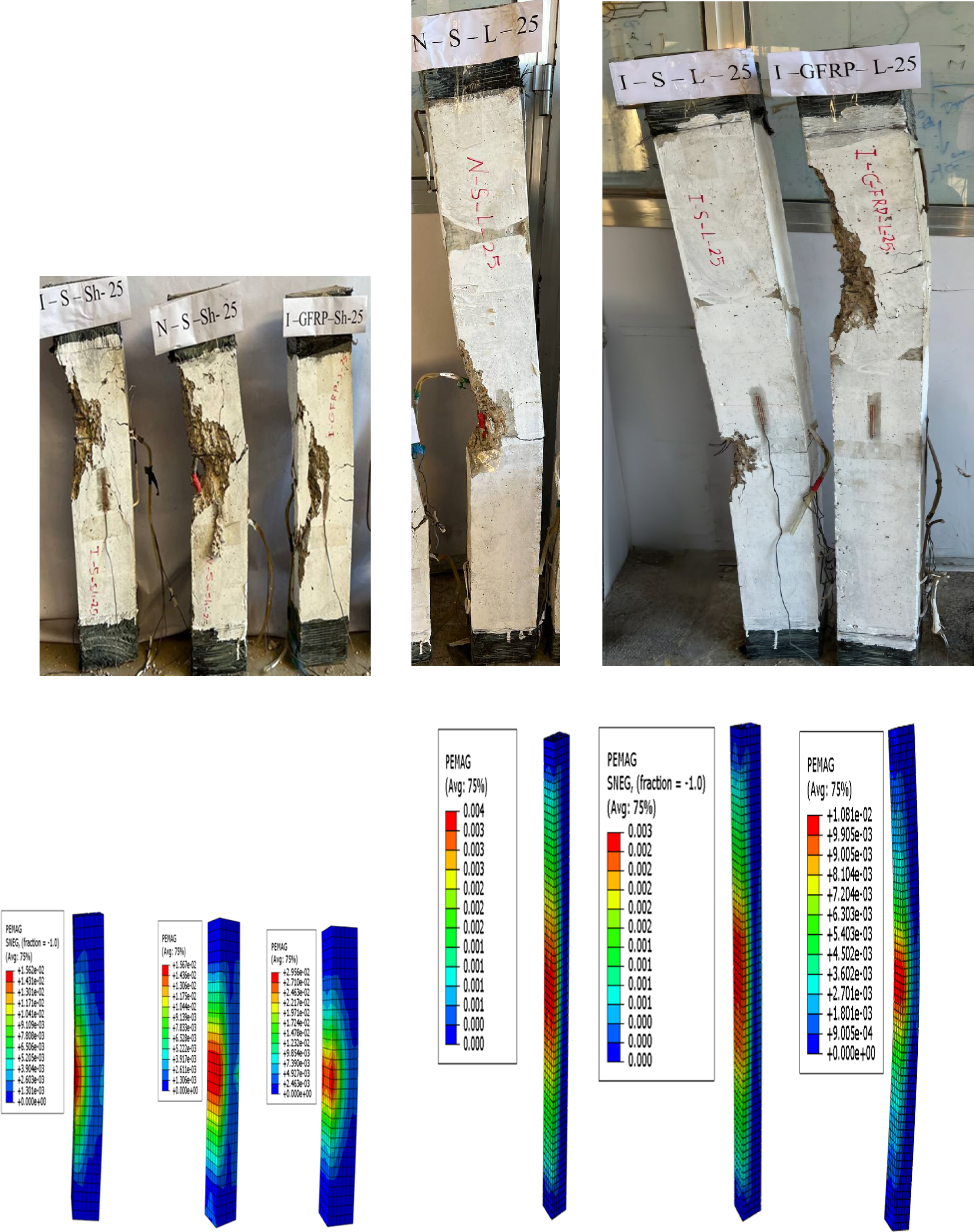
For columns tested under compression load with an eccentricity of 50 mm no tensile failure exhibits caused by tension in column cross section, causing yielding in reinforcement and I-sections and crushing of concrete in the compression zone. Specimens in the flexural test, subjected to two-point loading, first crack was observed at mid-span of the specimens, and the crack extended as the bending moment increased. Cracks extend upward the beam and new cracks appeared when increasing load at the same time crashing of concrete was occurred and reinforcement reaches to yield point, as shown in Figure 14. The failure mode for reinforced concrete specimens tested by flexural and eccentric loads represented by many cracks occurs in tension zone. Additionally large cracks were observed in specimens encased with I-section (steel and GFRP) and the spacing between the cracks was relatively uniform. The experimental failure mode for the tested specimens were identified using the FE model, which give a reasonable agreement with most of the tested specimens subjected to different types of loading. Failure mode of the experimental and FE analysis for long specimens under flexural load.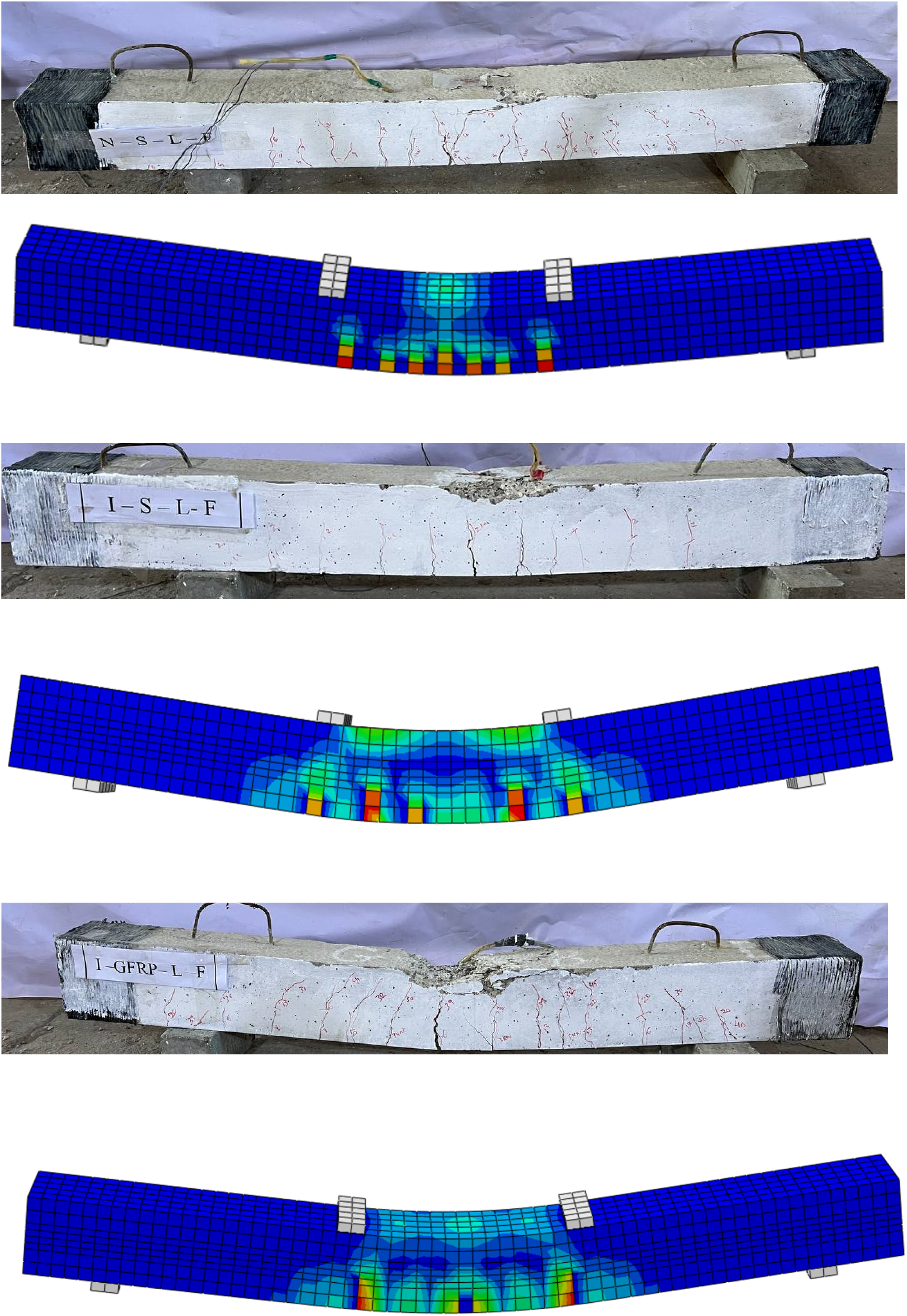
Interaction diagrams for specimens tested
The strength interaction diagram was drawn for specimens. (N-M) represents translating load from a real axial compression load to different collections of axial loads and bending moments to a real bending position. This research aims to produce an experimental and numerical interaction diagram by utilizing four points: axial concentric load represent a pure compression, two points symbolized eccentric load with eccentricity 25 mm and 50 mm and flexural load represented pure bending. These diagrams demonstrated acceptable axial load and bending moments for structural concrete members. By applying equation (1) flexural moment was found at the mid-height of column. And by using equation (2) flexural moment was calculated for beam.

Numerical load and bending moment were found by using FE method to generate interaction diagram for all specimens tested was utilized by ABAQUS computer software. The FE analysis was represented results for concentric, eccentric, and flexural loads for specimens reinforced and encased composite concrete column. Figure 15 displayed an interaction diagram of the experimental and FE results of the long set of the tested specimens. From the figures, it can be seen that (N–M) diagrams for the experimental and numerical results are almost symmetrical. (N-M) diagrams appeared that the reference columns (NSL) exhibited a significant decrease in the ultimate strength related to encase composite reinforced concrete columns (ECRCC) with I- section steel and GFRP, due to effect of I –sections. At the same time failure of the reinforced concrete column changed from compression-controlled to tension-controlled when the eccentricity of the applied load increased from 25 mm to 50 mm. Interaction diagrams for experimental and numerical long specimens.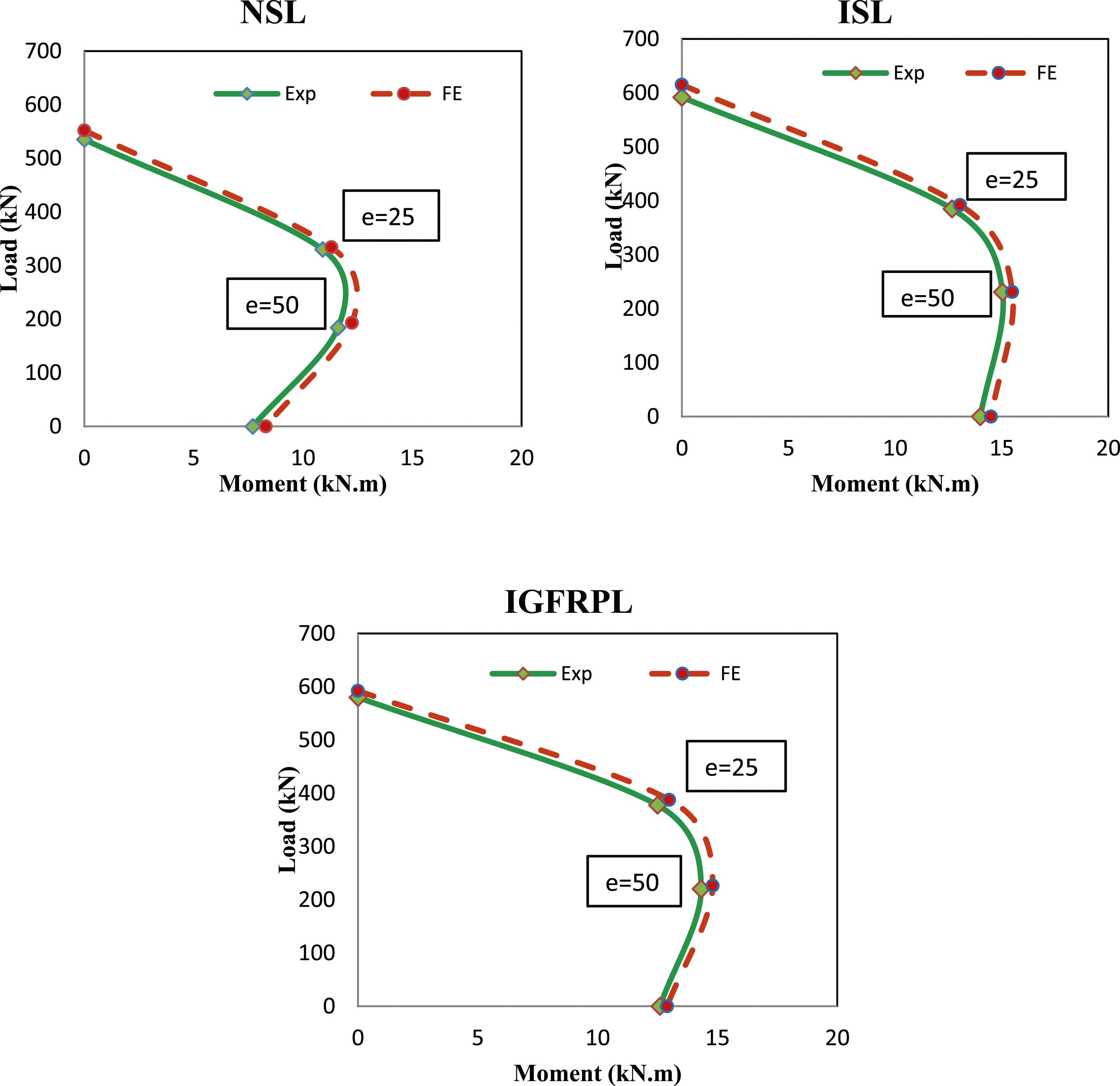
Analytical study
Due to limited of the specimens in the experimental test, FE verification was employed form the experimental tested results to find additionally analytical data for short beams. In the experimental work short specimens don’t tested under flexural test, so employed FE analysis to get the analytical results for these types of load and specimens (RCC, RCCES and RCCEG) by using the software ABAQUS. Reduction in specimen length was implemented to find ultimate load capacity, deflection and draw an interaction diagram for short specimens. Analytical specimens cross section were similar to the short column dimensions with 130 mm × 160 mm and length 750 mm with reinforced concrete beam and encased beam with I-section (steel and GFRP), these outcomes were used to plot interaction diagram for short column. The analytical deformations of the short beams were adopted in Figure 16. In the analytical data appeared enhancement in the ultimate load and deflections of the short specimens when compared with results obtained from analytical and experimental long specimens. An increased in ultimate load in analytical specimens (N-S-SH-F), (I-S-SH-F) and (I-GFRP-SH-F) about 123%, 125 and 104% and deflection improvement about 140%, 153% and 88% respectively related to result of the tested long specimens (N-S-L-F), (I-S-L-F) and (I-GFRP-L-F) as represented in Table 7. The analytical results of the load-deflection curve for short columns under flexural load. Analytical results of the ultimate load and deflection in short columns.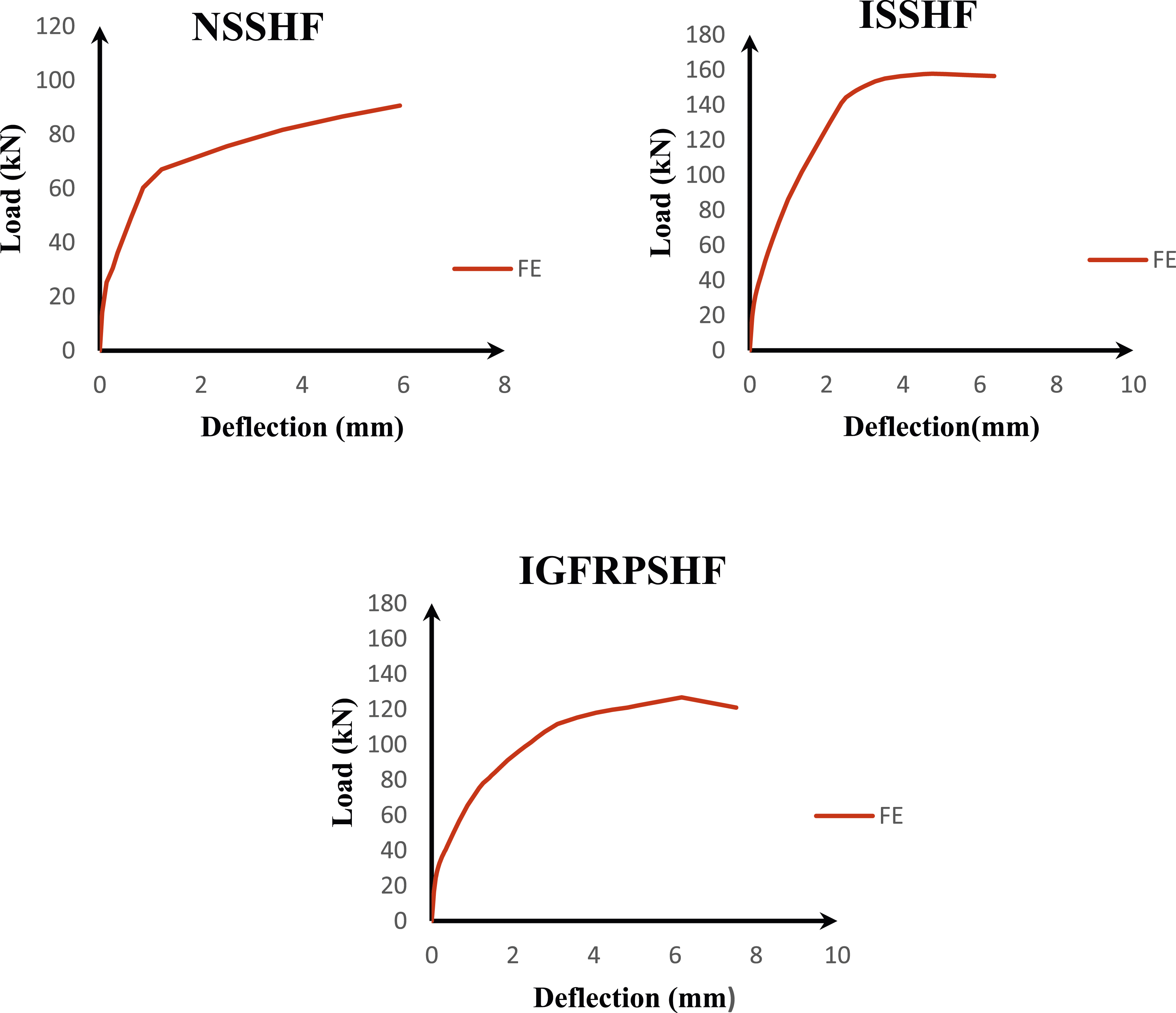

Figure 17 Indicate N-M diagrams for the analytical short columns, which appeared that all types of the short column which stiffer than the long column types due to the slenderness ratio effect on the column capacity. The analytical outcomes of the (N-M) diagram for the short columns.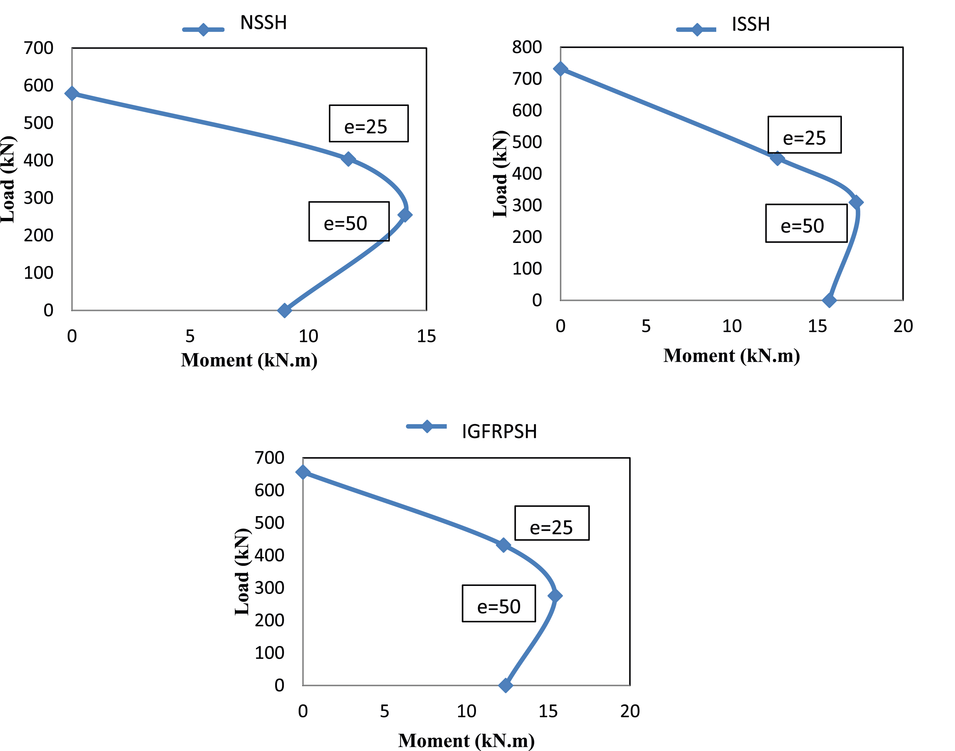
Conclusions
The manuscript presents the experimental and numerical investigation on the behavior of composite reinforced concrete columns encased by steel section and hybrid GFRP section. GFRP is primarily employed in members exposed to adverse environmental conditions. In recent years, few recommendations and standards permit the design with this type of material. The following important points can be focused: • The ultimate strength improved in reinforced and composite-encased short columns compared to slender columns, additionally lateral deflection decrease in short column, this is due to the effect of buckling occurring in long columns led to decrease column capacity and increase deformation. • The type of encased has a significant effect on column capacity. Maximum load capacity for reinforced encased slender columns (ISL0) and (IGFRPL0) improved by about 10% and 8.4% respectively when compared with reference column (NSL0) and the percentage increases more in columns (ISL25), (ISL50), (IGFRPL25) and (IGFRPL50) when subjected to load with eccentricity 25 mm and 50 mm reach about 16.6%, 22.7%, 14.4%, and 19.8% improvement, respectively, related to control columns (ISL0) and (IGFRPL0). While capacity of the encased short columns (ISSH0) and (IGFRPSH0) increased by 9.4% and 8.8% respectively, compared to (NSSH0) and these improvement increased about 11.5%, 10.1%, 20.1% and 13.4% for encased column under eccentric load 25 mm and 50 mm about (ISSH25), (IGFRPSH25), (ISSH50) and (IGFRPSH50) respectively, in comparison with control column (NSSH25) and (NSSH50). • Eccentric load has large effect on column capacity and deformation, as eccentricity increased showed a significant decrease in column capacity and increase in deformation, especially in long column because of the buckling effect. • In the tested specimens three kinds of failure mode were observed, depending on the tested specimen and load conditions, first mode was compression failure mode which appeared in all short columns and slender columns tested under concentric load. The second mode, observed in column tested under a 25 mm eccentric load, was a flexural–compression failure. And the last failure mode was observed in beams and long columns subjected to a 50 mm eccentricity. • Finite element analysis was used for simulation CRCCE by steel and hybrid GFRP section subjected to different load conditions. Results obtained from the experimental work were used to validate FE models, which showed good agreement with the experimental results in terms of maximum load, failure modes, and deformation. • Analytical study was estimated by using ABAQUS program for determining ultimate load and deflection of short specimens under flexural load and draw interaction diagrams. Analytical data obvious significance increase in maximum load and deflection in short specimens in compression with the long specimens and stiffer in N-M diagrams. • The cost of the I-GFRP (hybrid material) is lower than the steel section, equivalent to about 60% −70% of the manufacturing cost of the I-steel, in addition to advantages like light weight, ease use in construction, high tensile strength, and corrosion resistance.
Footnotes
Declaration of Conflicting Interests
The author(s) declared no potential conflicts of interest with respect to the research, authorship, and/or publication of this article.
Funding
The author(s) received no financial support for the research, authorship, and/or publication of this article.