



Abstract
The buckling phenomenon and deformation distribution of the laminated rubber bearing, taking into account the crack effect, are predicted by the period structure assumption and transfer matrix method (TMM). A concentrated flexural spring is utilized to simulate the local flexural stiffness deterioration that arises from the crack. The solutions of the individual rubber layer derived from Haringx’s column theory are formulated in the development of the crack model, and the inside steel shim is modeled as a rigid body whose transfer relation is then combined with that of the rubber layer. The resulting total transfer matrix, along with the boundary conditions, is applied to determine the horizontal stiffness and critical buckling load of the bearing with a single, or multiple cracks. Experimental data demonstrates the validity of the proposed analytical model. The results show that for a single crack, the least decrease in critical buckling load occurs when the crack is vertically centered along the height of the bearing; when the crack is closer to the top or bottom of the bearing, the critical buckling load may reduce by about half for a high level of deterioration. Two or multiple cracks make the critical buckling load decreased rapidly, especially for cracks in different rubber layers; nevertheless, not only the nearer these cracks approach the bearing center but also the much closer these cracks are together, the less the critical buckling load decreases.
Introduction
Base isolation, which often adopts multilayer elastomeric bearings, provides an effective and economic approach to mitigate the vibration transmitted to the superstructure. Elastomeric laminated rubber isolation bearings are arranged with rubber layers periodically bonded to rigid steel shims, therefore not only offering sufficient axial stiffness to sustain the weight of the system but also reserving necessary flexibility in the horizontal direction (Kelly and Takhirov, 2007; Tsai and Hsueh, 2001; Warn et al., 2007). The buckling analysis of the bearings under compressive force is well known, and has drawn the attention of many researchers. Stanton et al. (1990) as well as Imbimbo and Kelly (1997a, 1997b), for example, investigated the critical buckling load and buckling behavior of laminated rubber isolators according to the theory of Haringx’s equivalent continuous column (Haringx, 1949; Kelly, 1997), by considering the shear and flexural stiffness of the bearing. This theory has also been adopted, together with the stiffness matrix method, by Chang (2002) to predict the critical buckling force of the laminated rubber bearings for various geometric arrangements and boundary conditions. Koh and Kelly (1988, 1989) introduced a simple two-spring model to study the mechanical characteristics and stability behavior for the laminated rubber isolator. Further, Kikuchi et al. (2010) extended the Koh-Kelly model to three dimensions by adding a series of shear springs and axial springs. Mazda and Shiojiri (1993) used the transfer matrix method (TMM) to predict the buckling behavior of laminated rubber bearings. Utilizing TMM, Ellakany et al. (2004), Ellakany and Tablia (2010) investigated the static and free vibration of composite structures with a shear elastic interface. It was promising that TMM exhibited the advantages of simplicity and fewer iterations. The general problem of the combination of the rubber bearing and other elastomers was given by Wang et al. (2024) and Xu et al. (2023) through experimental study and finite element method. The refined numerical modeling for the rubber bearings considering the hysteretic strength degradation was developed and verified from experimental study performed by Zheng et al. (2022).
Cracks often occur in the bearings because of corrosion and aging of the rubber, rust or pitting of the steel shims, cavitation as well as other factors such as an earthquake (Yin et al., 2024). Chou and Huang (2011) predicted the crack initiation and propagation in rubber bearings, indicating that fatigue cracks initiated first at the outermost boundary between rubber and steel plates. Different damages including the cracks were collected and labeled for condition classification to improve the damage identification of rubber bearings (Cui et al., 2021). Zhang et al. (2022) treated the damage isolation bearing as a periodic structure to propose a damage detection scheme. The model assumed the change in shear modulus of the rubber layer (Ding et al., 2019) due to the ageing of the rubber material. Various identification frameworks to detect the deterioration of rubber bearings due to crack damage, rubber rupture and bearing void were proposed (Gao et al., 2023; Zeng et al., 2024; Zhang et al., 2024). Matsuzaki (2022) investigated the effects of capacity hierarchy and the ageing deterioration of rubber bearings on the predominant ultimate failure mode, and presented that the seismic safety could be improved by setting an adequate capacity hierarchy. However, to date, scarce work has been performed on the buckling problem of cracked laminated rubber isolators. Whether the buckling of the bearing displays high sensitivity to the local crack is undetermined, therefore it is quite valuable to take into account the influences of the cracks on the horizontal stiffness and the critical buckling load of the bearing.
The buckling analysis of the cracked laminated rubber isolators may be performed identical to that of a cracked composite column whereas governed by the low shear stiffness. Zapata-Medina et al. (2010) studied the buckling of a cracked uniform Timoshenko column considering the influence of shear deformation based on closed formulas. Arboleda-Monsalve et al. (2007) examined the buckling problem of cracked Timoshenko beam-columns with generalized boundary conditions, and presented the variation of critical buckling loads derived from different models such as the simple Bernoulli-Euler beam and the relatively more sophisticated Rayleigh, Shear as well as Timoshenko beam. Takahashi (1999) investigated the stability of a non-uniform cracked Timoshenko beam including a compressive load and a tangential follower force distributed over the center line. However, these buckling analyses have been confined to the Timoshenko column with only one single crack. The influence of multiple cracks on the buckling and stability of Timoshenko beam-columns are investigated by Fan and Zheng (2003) through modified Fourier series. Caddemi et al. (2013) have applied distribution theory to analyze the stability of the uniform Timoshenko column in appearance of multiple cracks under tensile or compressive forces. Li (2001, 2003) studied the decrease of the critical buckling force, due to an arbitrary number of cracks, of multi-step uniform columns with shear deformation and non-uniform columns subjected to compressive loads, by utilizing the transfer matrix approach. This approach allows for the critical buckling load to be determined conveniently through a determinant of order two.
In the present work, the influences of the deterioration level and number of the crack on the bearing buckling and deformation distribution are examined. The interest lies in determination, in terms of the crack location, of which section is the most unfavorable and what the critical buckling load variation results from a single, two or multiple cracks. The same combination of periodic structure assumption and the transfer matrix approach is applied as in the study of laminated rubber bearings without any damage (Ding et al., 2017). The closed-form solutions of the individual rubber layer behaving as a Haringx’s column proposed by Chang (2002) are formulated in the development of the crack model, and the inside steel shims, described using the rigid body assumption, are modeled to establish the system transfer matrix. The horizontal stiffness and critical buckling load of the laminated rubber bearing are assessed by analyzing the horizontal force and the lateral displacement at the upper surface of the isolator, derived from the system transfer matrix. The accuracy of the specific model is validated through recuperating the cracked model into the perfect model.
Theoretical derivation of cracked laminated rubber bearing
Assumptions
The typical periodic element of the laminated rubber isolator consists of a rubber layer and a steel shim, as depicted in Figure 1. The number of the rubber layers is Typical laminated rubber bearing. (Figure from Chang (2002)).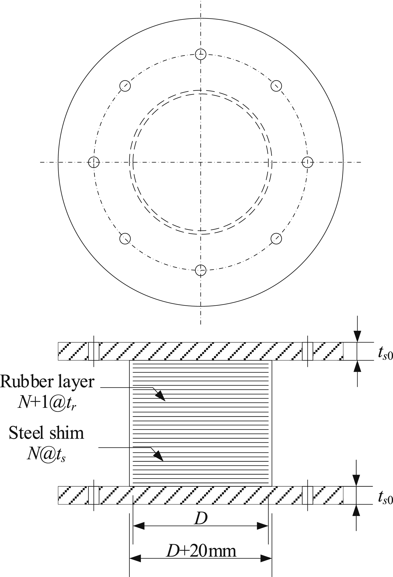
is Cracked rubber layer: (a) the i-th rubber layer with n
i
cracks; (b) a flexural spring to simulate a crack.
Governing equations of one rubber layer with cracks
Inspired by Chang’s methodology (2002), herein the Haringx’ theory is applied to develop the model of the first rubber segment in the i-th rubber layer for
perpendicular to the deformed axis after deformation, such that the corresponding deformed configuration of the first rubber segment is shown in Figure 3(a). The deflection can therefore be defined in terms of lateral displacement of the central line, Loads and deformation of the first rubber segment in the i-th rubber layer: (a) full configuration; (b) cross section. (Figure adapted from Chang (2002)).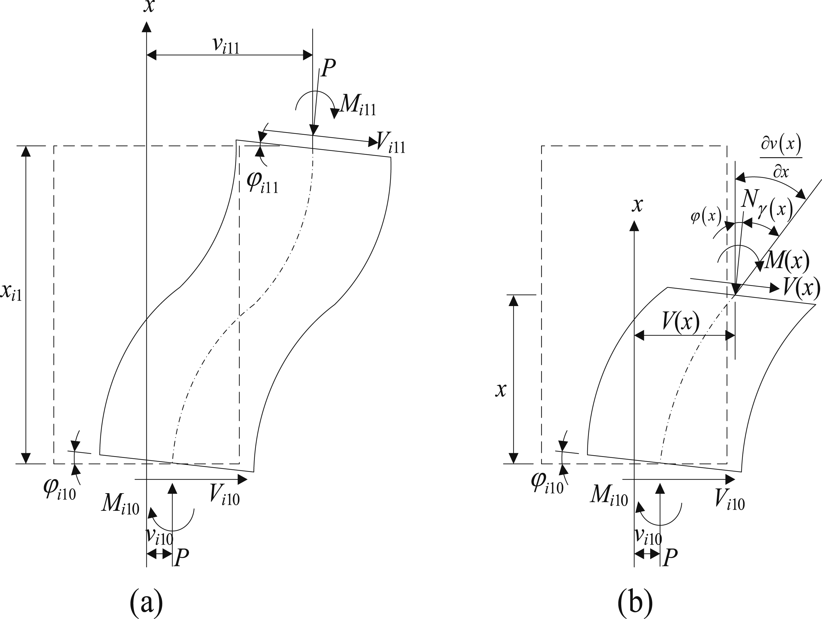


Herein only small rotation


After some manipulation,

Substituting



By applying the relationship between



The bending moment and shear force in the cross section are hence rewritten in terms of equations (1), (2), and (6) as follows:


As shown in Figure 3, the deformation of the lower point


Substituting equation (6) into equation (9) gives the solutions


Accordingly, inserting equation (10) into equations (6) and (8), yields the deflection and the internal force
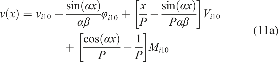



Then, equations (11a)-(11d) are combined to obtain the matrix expression:


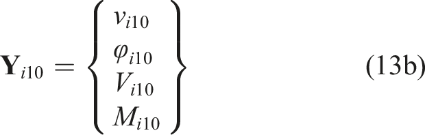
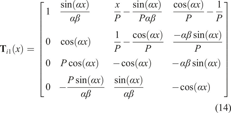
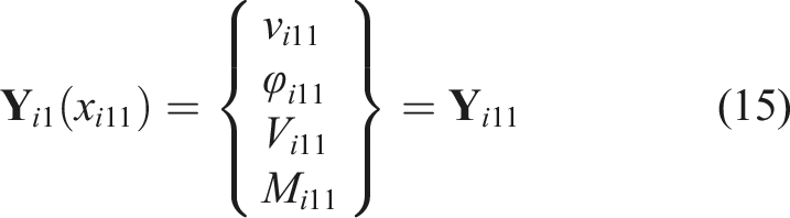
As shown in Figure 2, at the interface of the first and second rubber segments, the displacement, shear force and bending moment are needed to be continuous and the rotation has a jump, which provides the following compatibility and equilibrium conditions at the cracked section
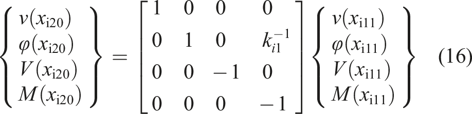
Making use of equations (16) and (12) leads to

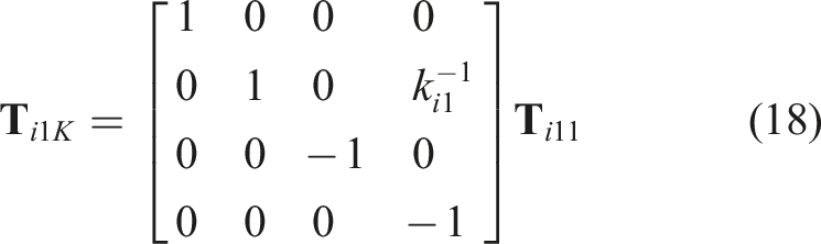
The equation of the (


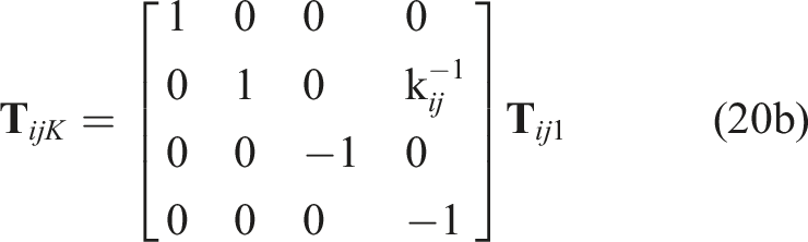

A flow diagram explaining the details of the TMM for cracks in one rubber layer is also shown in Figure 4. Especially, if a crack is located at the upper end of the i-th rubber layer, Flow diagram of the TMM for cracks in the i-th rubber layer.
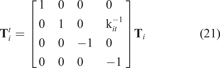
The equation for the crack at the lower end or both ends of the i-th rubber layer can be obtained similarly.
Transfer matrix for a cracked periodic element
As described above, the i-th periodic element shown in Figure 5 is provided with the i-th rubber layer and the i-th steel shim, and it is assumed that the rubber layer contributes completely to the deformations of the isolator, as opposed to the steel shim, that is considered to exhibit only the motion form of a rigid body (Chang, 2002). In this manner, the deflections and forces at the upper surface of the i-th rigid steel shim shown in Figure 5 are given by Load and deflection notation: (a) a cracked rubber layer; (b) a cracked rubber layer bonded with a steel shim. (Figure adapted from Chang (2002)).




where

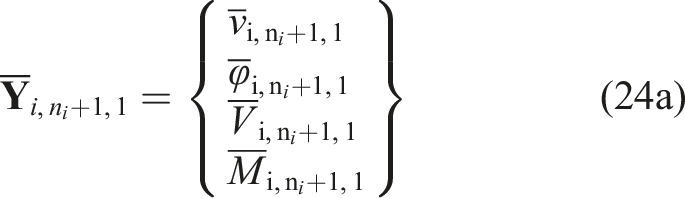
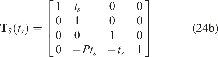
Combining equations (19) and (23), the state vector at the upper surface of the steel shim can be connected with that at the lower end of the i-th rubber layer through


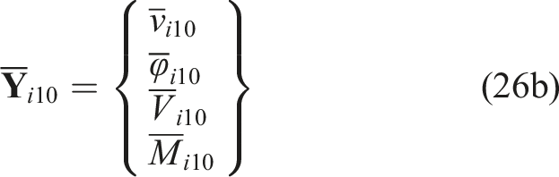
Taking into account the compatibility as well as the equilibrium conditions at the interface between the i-th and the i+1-th periodic elements lead to:


Using equations (27) and (25) in order to eliminate

A typical laminated rubber isolator, displayed in Figure 1, generally includes N periodic elements and an extra rubber layer, as well as one upper and lower rigid end steel plates, such that the system transfer matrix can be conveniently written in the form

Application of the system transfer matrix


Solution of cracked laminated rubber bearings
In most situations, the laminated rubber isolator is restrained against any displacement and cross section rotation at the bottom end, while it is permitted to move in the horizontal direction but yet constrained from rotation at the top end. An axial compressive load




So far the state vectors at the both ends, which can be used to assess the mechanical behaviour of the whole cracked laminated rubber isolation bearing, have been determined. In other words, the horizontal stiffness can be easily obtained from the ratio of the applied horizontal force to the lateral displacement at the upper surface of the isolation bearing, by using equation (32). For the case of a high center of gravity, large-angle deformations may occur, hence the application of this derivation may be invalid.
Numerical examples
The typical circular laminated rubber isolation bearing is considered in the following numerical analysis. The number of rubber layers is 20 with
For the purpose of highlighting the contribution of the rubber protective cover to the shear rigidity of the analysis composite model, the overall shear area

Due to the single circular rubber layer reinforced with two rigid steel shims, the flexural rigidity is represented according to Gent and Meinecke’s theory (1970) as follows:

A single crack
The performance of a bearing with only a single crack is first investigated both in terms of horizontal stiffness and critical buckling load and in terms of the deformation. The variations of the horizontal stiffness with various compressive forces for a single crack in the entire bearing are plotted in Figure 6, where different crack locations are considered and each crack is located at the center of each rubber layer, namely Variation of horizontal stiffness with compression force for a single crack and different crack locations: (a) 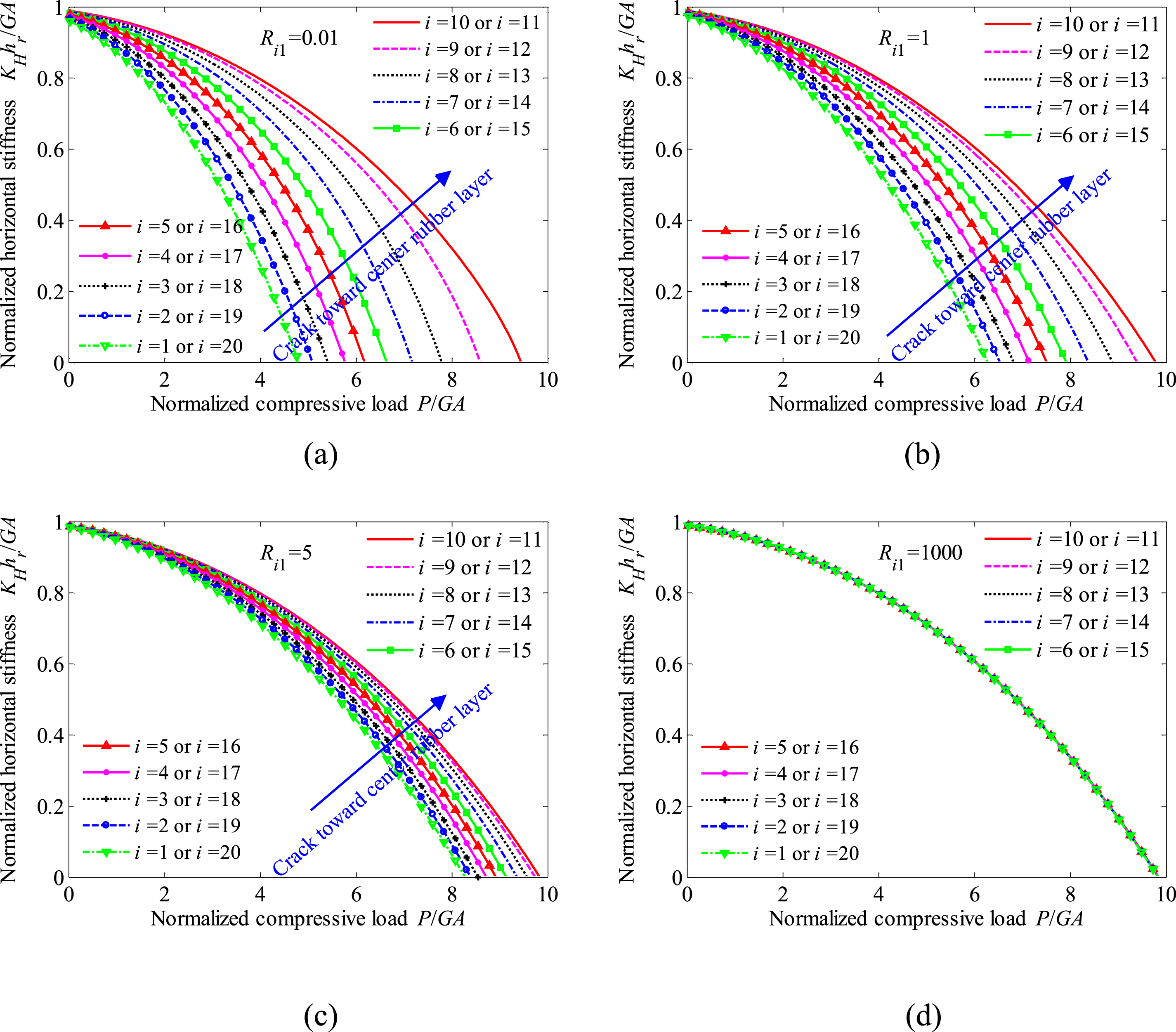
Comparing the four graphs in Figure 6, one can find that the horizontal stiffness and critical load display little sensitivity to the section deterioration level for
A comparison between the present result for the particular case Comparison with numerical and experimental results.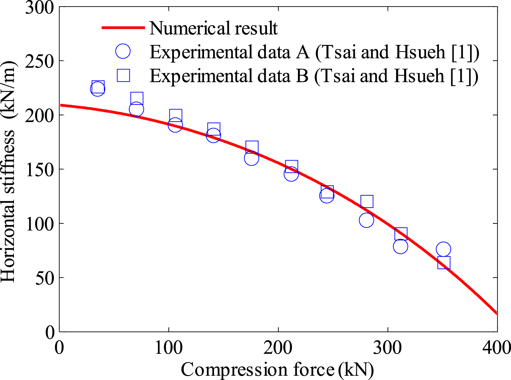
The influences of the crack location and deterioration level on the critical buckling load are analyzed in an explicit and comprehensive manner in Figure 8, which again highlights that under the same deterioration level, a high value of the critical buckling load is generated if the crack position appears at the center of the bearing and substantially decreases as the crack section shifts toward the upper or lower end of the isolation bearing. Influence of crack location and deterioration level on the critical buckling load for a single crack at 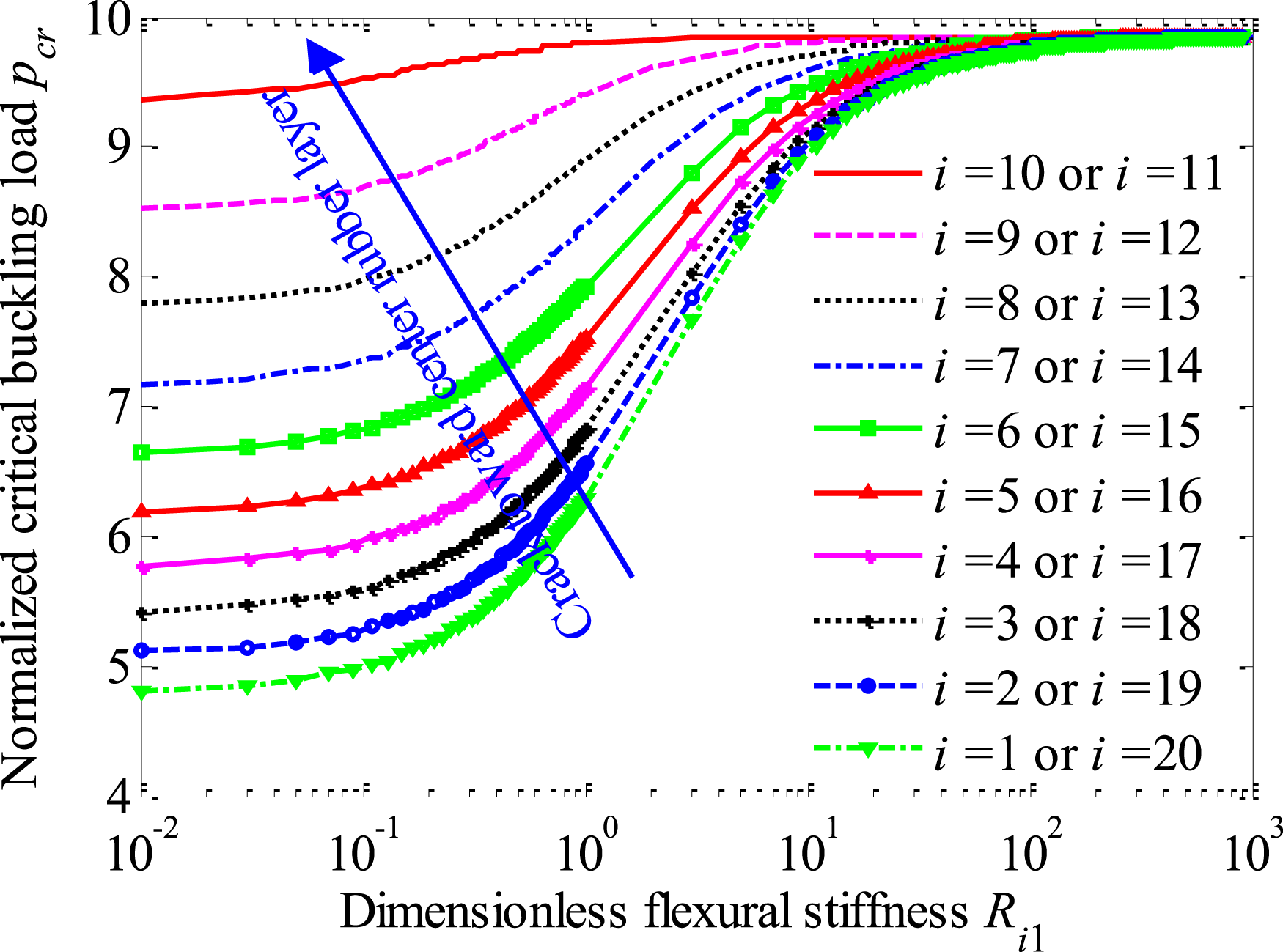
When Distribution of lateral displacement Distribution of rotation 

A single crack in different locations ( Horizontal stiffnesses for varying crack location in a rubber layer for a single crack: (a) 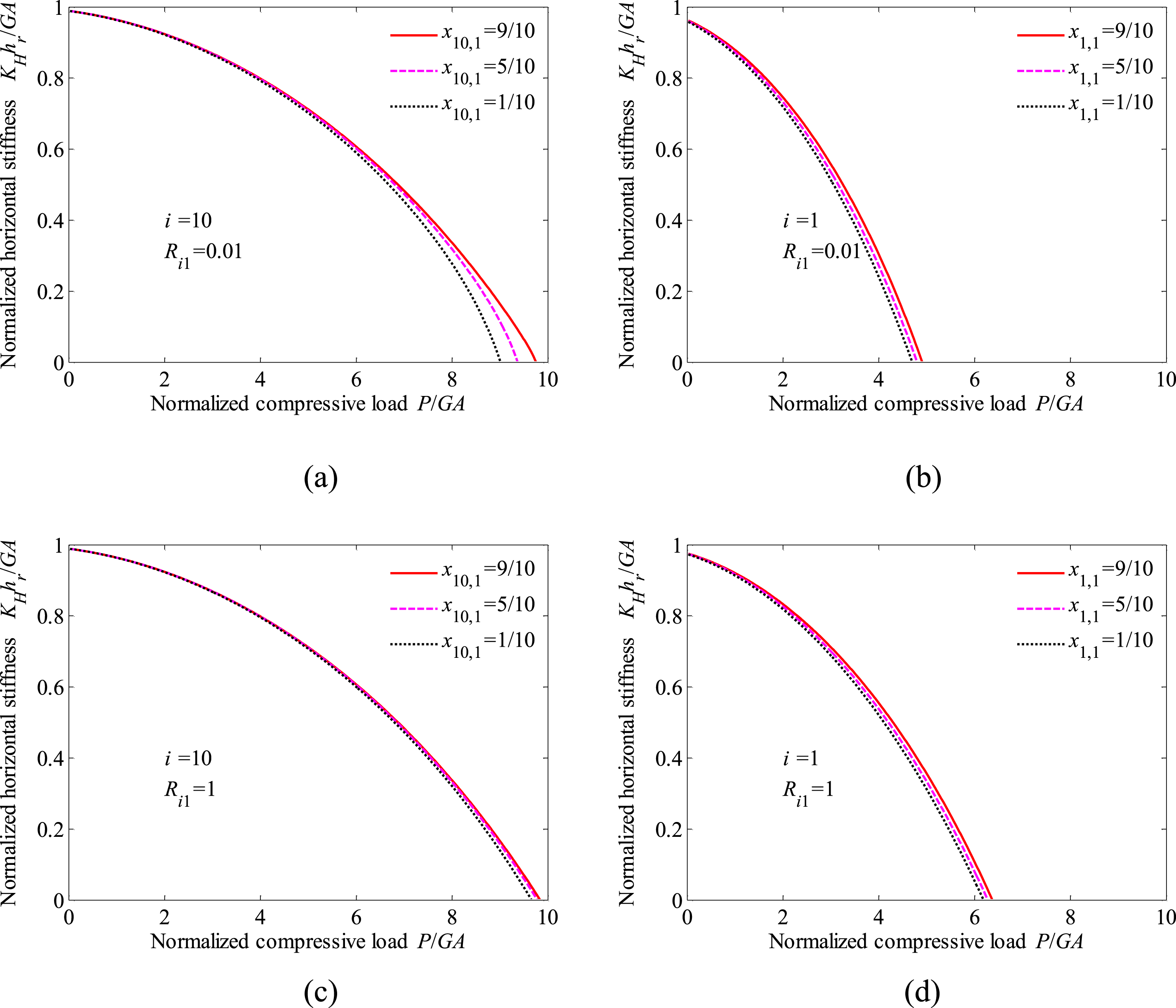
Two cracks
The analysis is performed for two cracks in different rubber layers and within a rubber layer. The purpose is to analyze the effects of two cracks on the horizontal stiffness, critical buckling load and deformation and compare the results of bearings with a single and two cracks.
Two cracks in different rubber layers
Configurations for two cracks in two different rubber layers.
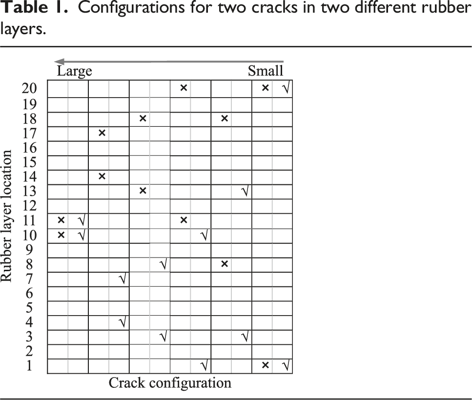
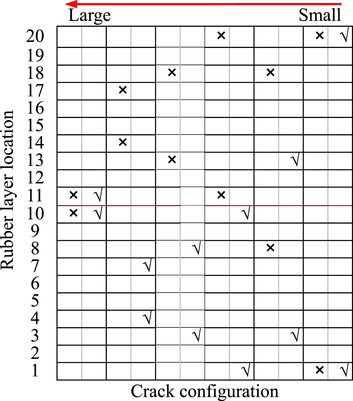
The horizontal stiffnesses obtained for the six configurations with two different deterioration levels are displayed in Figure 12. For the same compressive force, the horizontal stiffness for the bearing with two centralized cracks in the 10th and 11th rubber layers is higher than that for the bearing with one crack in the 11th rubber layer and the other in the 20th rubber layer. Of the first set and the configuration of cracks in the 11th and 20th rubber layers, the horizontal stiffness for the bearing with the two decentralized cracks in the 1st and 20th rubber layers is the lowest. For the second set, the horizontal stiffness for the bearing with cracks in the 14th and 17th rubber layers is higher than in the 13th and 18th rubber layers. It is interesting to find that the horizontal stiffness for the bearing with cracks in the 13th and 18th rubber layers is then higher than in the 11th and 20th rubber layers, which again shows that the decentralized cracks make the horizontal stiffness low. Even though the 8th and 13th rubber layers are symmetrical in the bearing, the horizontal stiffnesses of the configurations of cracks in the 13th and 18th rubber layers and the 8th and 18th are not the same, and the latter is lower than the former. Therefore, it can be concluded from these observations that not only the nearer the two cracks approach the bearing center but also the much closer the two cracks are together, making the equivalent compressive length shorter, the higher the horizontal stiffnesses are. Variation of horizontal stiffness for two cracks in different rubber layers: (a) 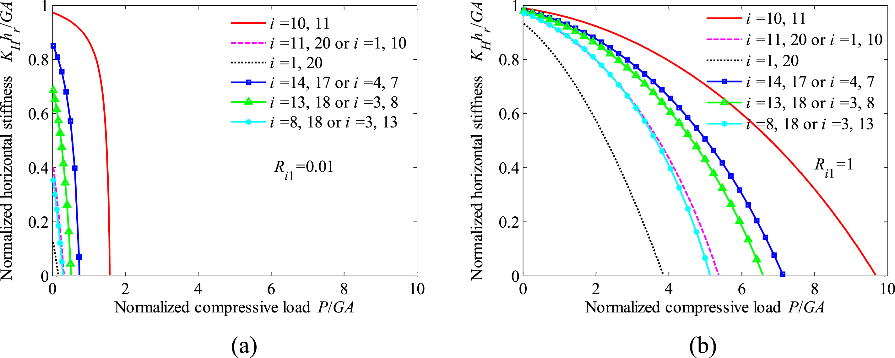
The critical buckling loads obtained for the bearing with two crack sections in two different rubber layers for the same deterioration level are displayed in Figure 13. Notice that the top curve is obtained by taking the two cracks respectively centralized in the 10th and 11th rubber layers. As the crack locations move apart, the critical buckling load decreases. The lowest curve corresponds to the configuration by taking the two cracks respectively decentralized in the 1st and 20th rubber layers. Therefore, the two curves can be considered representative of the limit critical buckling load of the bearing with two cracks in different rubber layers. Moreover, the critical buckling load approaches zero (0.19 when Influence of crack location and deterioration level on the critical buckling load for two cracks in different rubber layers.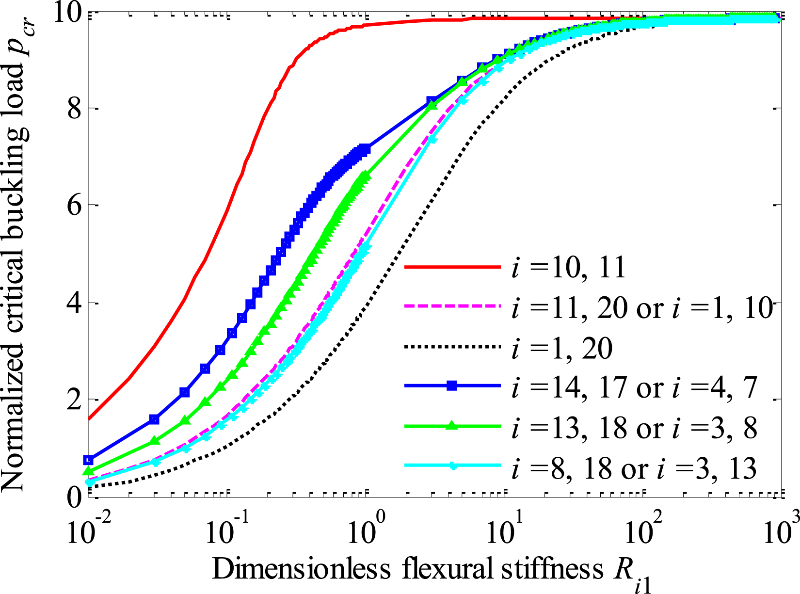
The internal deformation profiles for two crack sections with Distribution of deformation over bearing height for different crack locations: (a), (b) lateral displacement 
Two cracks in one rubber layer
The horizontal stiffness for the bearing with two crack sections within one rubber layer for Variation of horizontal stiffness with compression force for two cracks in one rubber layer: (a) 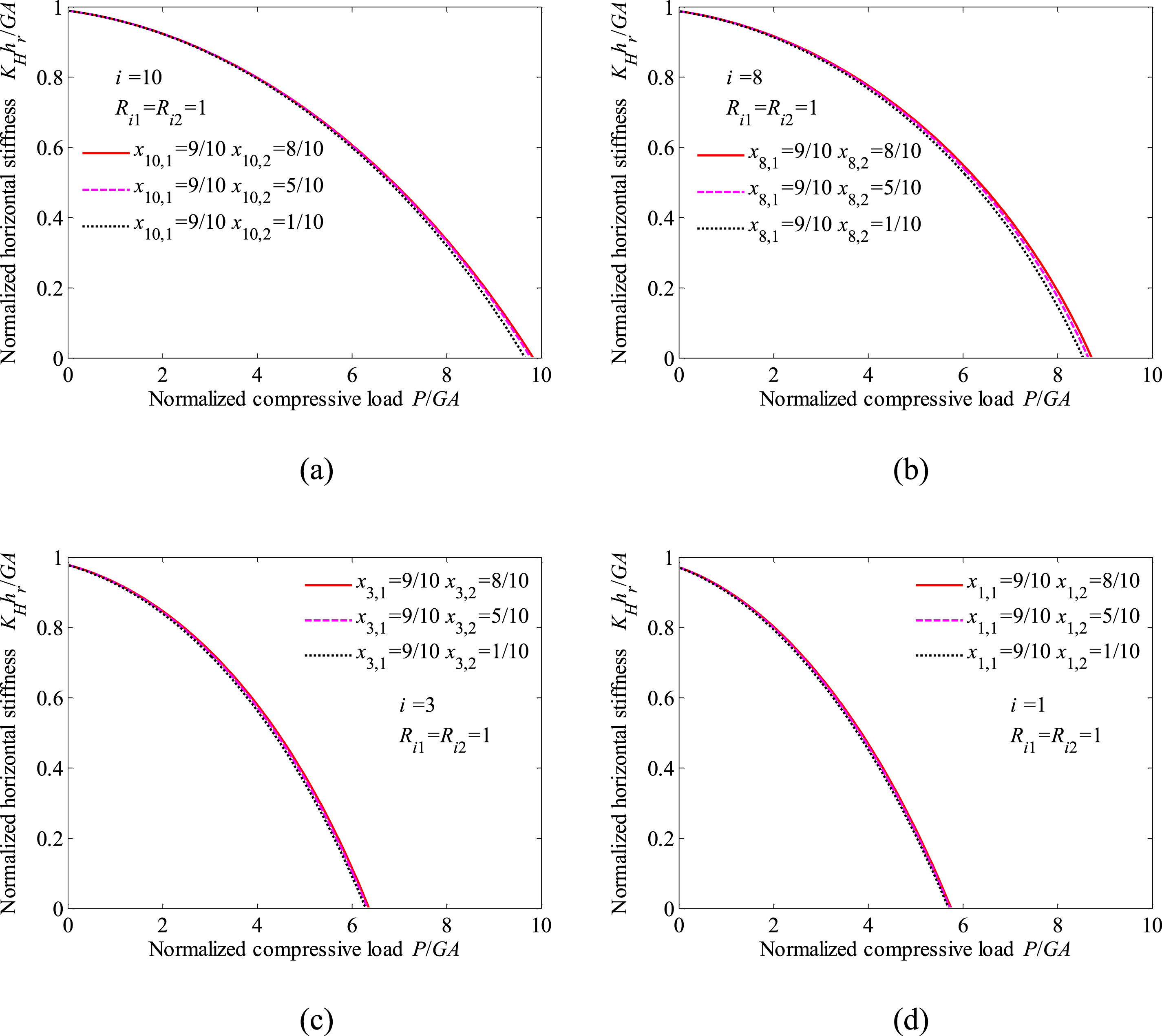
Take Influence of crack location and deterioration level on the critical buckling load for two cracks in one rubber layer.
Multiple cracks
The influence of three cracks in different locations on the horizontal stiffness and critical buckling load of the bearing is evaluated. A comparison is carried out among the performance of bearings with only a single crack, two cracks and three cracks.
Three cracks in three different rubber layers
Configurations for three cracks in three different rubber layers.


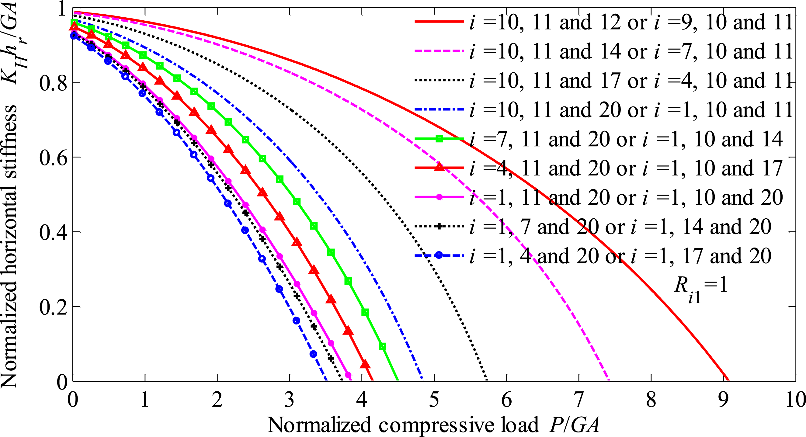
Variation of horizontal stiffness for three cracks in three different rubber layers for the same deterioration level

Influence of crack location and deterioration level on the critical buckling load for three cracks in three different rubber layers.
Comparison of configurations for three cracks in three rubber layers and configurations for a single and two cracks.

Three cracks in two rubber layers
Configurations for three cracks in two rubber layers.

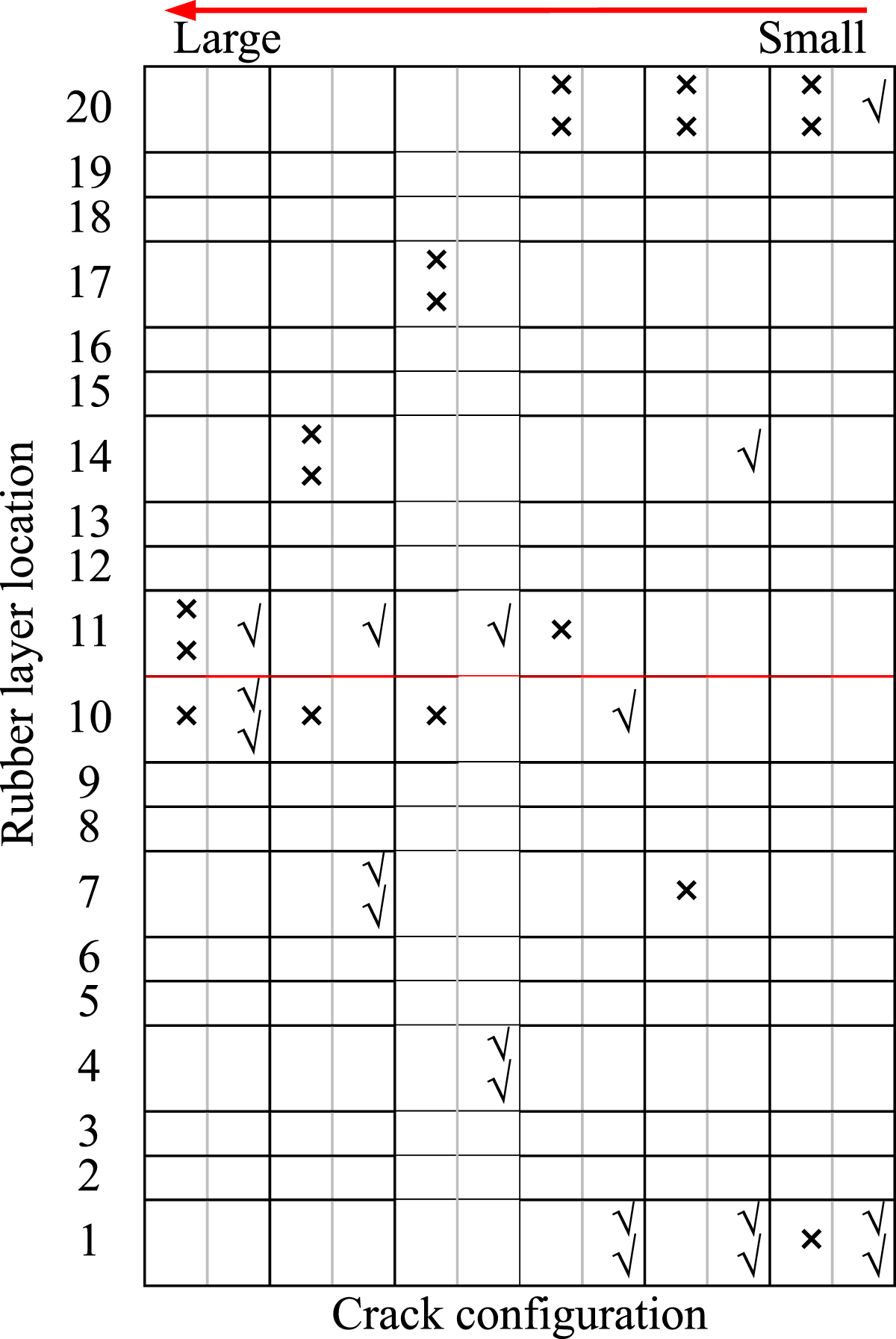

Variation of horizontal stiffness for three cracks in two rubber layers for the same deterioration level
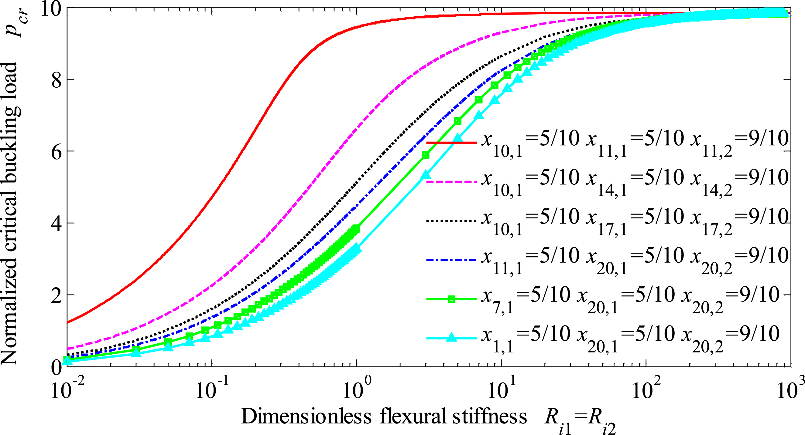
Influence of crack location and deterioration level on the critical buckling load for three cracks in two rubber layers.
Comparison of configurations for three cracks in two rubber layers and configurations for a single and two cracks.
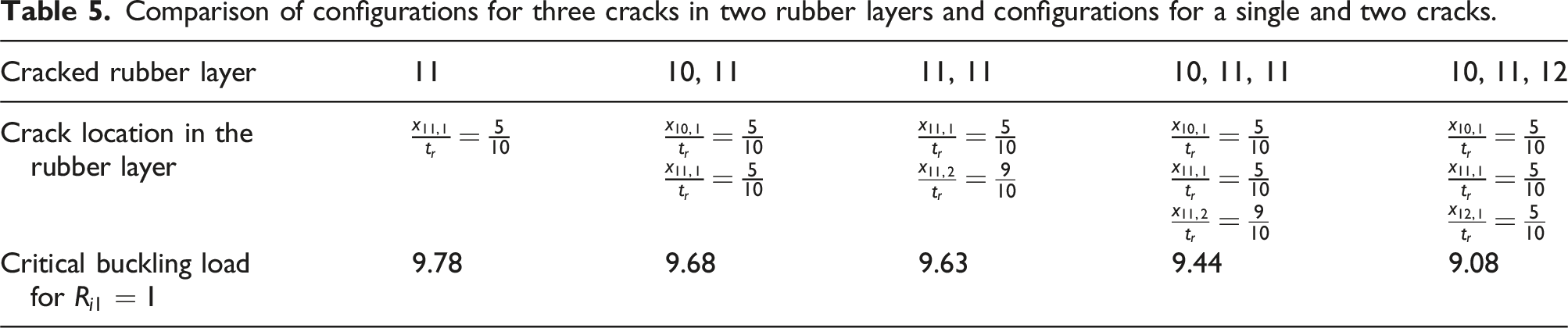
Adding another crack (
Three cracks in one rubber layer
Similar calculations are repeated for three cracks within only one rubber layer. The results are shown in Figures 21 and 22, where Variation of horizontal stiffness for three cracks within one rubber layer for the same deterioration level Influence of crack location and deterioration level on the critical buckling load for three cracks within one rubber layer.
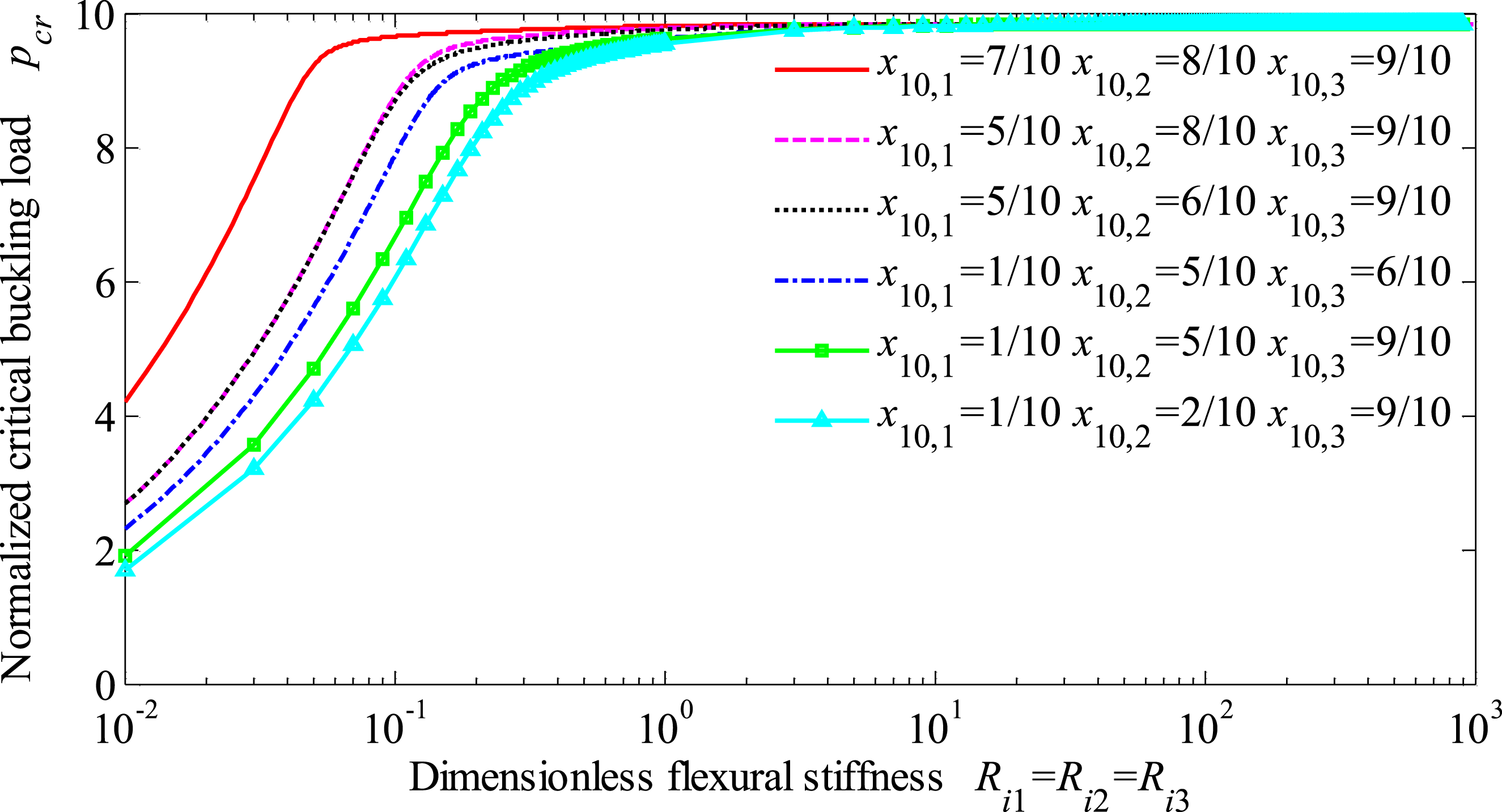
Comparison of configurations for three cracks in one rubber layer and configurations for a single and two cracks.

Conclusions
A period structure assumption and transfer matrix formulation, along with the closed-form solutions based on the Haringx column theory for the rubber layer as well as the motion principle of the rigid body for the steel shim, are derived to analyze the effects of a single or multiple cracks, on the buckling and deformation distribution of a laminated rubber isolation bearing. The proposed approach presents an efficient tool for evaluating the horizontal stiffness and critical buckling load of the bearings with an arbitrary number of cracks, by only changing the number of transfer matrices above and below the crack section and the height of each segmented rubber layer with cracks. The results indicate that the horizontal stiffness and critical load depend on the number, location and level of deterioration. For a single crack section, there exists the least decrease in critical buckling load when the crack is at the center of the bearing, and moving from the situation of a bearing with the crack located at the center to the situation at the top or bottom, gives a reduction of about one-half of the critical buckling load for a high level of deterioration. However, if the crack appears at the center of the bearing, the critical buckling load is not sensitive to the level of deterioration. Furthermore, the crack leads to an increase in both the lateral displacement and the internal rotation. Cracks in two or multiple rubber layers drastically reduce the critical buckling load especially for cracks in different rubber layers. Whereas if one or two cracks already exist in the bearing, the addition of another crack around the bearing center, making the final cracks more gathered, results in a less decrease in critical buckling load. A consideration of the crack effect is necessary for effectively predicting the mechanical properties of the damaged bearings. The verification of the methodology and model still stand for based on the limited set of test results, therefore further investigation is needed and recommended.
Footnotes

Funding
The author(s) disclosed receipt of the following financial support for the research, authorship and/or publication of this article: The authors gratefully acknowledge the financial support for this research provided by the National Natural Science Foundation of China (Grant No. 51908521, 52478319 and 52178370).
Declaration of conflicting interests
The author(s) declared no potential conflicts of interest with respect to the research, authorship, and/or publication of this article.