
Abstract
This study investigates the seismic performance of shallow socket bridge piers used in the Zhengzhou-Jinan high-speed railway. In-situ full-scale quasi-static cyclic load tests and finite element simulations using ABAQUS were conducted through quasi-static analyses. After validating the finite element model’s accuracy, a comprehensive parametric study was performed to assess the effectiveness of the shallow socket connection and systematically evaluate the influence of key design parameters, including socket depth, pier diameter, and aspect ratio. The results indicate that reasonably designed shallow socket bridge piers exhibit mechanical performance comparable to cast-in-place integral bridge piers. The mechanical performance of socket bridge piers is governed by the weakest component. Increasing the socket depth markedly improves the post-peak ductility of the pier, resulting in ductile bending failure. While a large pier diameter improves the load-bearing capacity, it also raises the likelihood of brittle failure in the socket connection components. In addition, increasing the height of the pier columns substantially compromises seismic performance, altering the failure mode of the bridge piers.
Keywords
Introduction
The socket connection involves splicing prefabricated piers into sockets in bearing platforms and grouting the interface, offering advantages in assembly simplicity, reduced labor, and cost efficiency (Xie et al., 2020; Zou et al., 2023).
Conventional cast-in-place (CIP) piers rely on continuous longitudinal reinforcement. In contrast, reinforcement are discontinuous at socket pier joints, creating a potential weak region. Under seismic loading, horizontal forces may induce damage at this joint due to repeated overload, which is difficult to repair. This seismic vulnerability has limited the broader adoption of socket piers (Liu et al., 2022; Zhang et al., 2021).
The socket connection itself is critical to pier performance (Xu et al., 2021), with the socket depth (embedment depth of the column into the platform) being a key factor influencing mechanical behavior. Extensive research has conservatively suggested that an “equivalent CIP” performance requires a socket depth of at least 1.0 D (where D is the pier cross-section dimension). Early research and codes conservatively recommend depths ≥1.0D (where D is the pier diameter) for “equivalent CIP” performance, with specific values ranging from 1.0D to 2.0D depending on standards and interface conditions. For instance, Chinese railway standards require >1.4D (TBJ 107-92, 1992), while Brazilian specifications stipulate 1.6D–2.0D depending on surface roughness (Li et al., 2018). Research findings also span a similar range: Osanai et al. (1996) suggested 1.25D–1.5D; Motaref (2011) and Mehrsoroush and Saiidi (2016) validated depths of 1.5D and 1.2D, respectively; and several studies have confirmed that ≥1.0D can provide CIP-like behavior (Culmo et al., 2018; Jones et al., 2020; Mashal et al., 2013; Mashal and Alessandro, 2014; Mohebbi and Saiidi, 2017).
While the aforementioned socket depths (≥1.0D) ensure performance comparable to CIP piers, they necessitate large socket holes in the footing or cap beam. This increases voids within these components, raising concerns regarding construction costs, complexity, and potential adverse effects on local reinforcement and structural mechanics. For railway bridge piers with large cross-sections, strict adherence to these depth requirements may result in impractically thick bearing platforms driving interest in shallower sockets (<1.0D). Several recent studies have argued that early depth requirements were overly conservative, proposing that depths below 1.0 D are achievable with appropriate measures. For instance, Han et al. (2022) suggested using rough treatments for the socket section interface to achieve depths below 1.0 D. Xu et al. (2021) and Zhang et al. (2021) demonstrated through quasi-static tests that socket depths of 0.56 D and 0.8 D, respectively, could maintain consistent failure modes and seismic performance comparable to CIP piers.
However, it is crucial to position the current study within the context of the authors’ prior work to clarify its novelty. Our research group has previously investigated shallow socket piers. Zou et al. (2023) conducted an in-situ full-scale test on a double-column hollow pier with a socket depth of 0.44D, confirming its global reliability. Zou et al. (2019) then studied the influence of shear key geometry. However, a comprehensive understanding of shallow socket piers (<1.0D) remains incomplete. Critical gaps include the systematic quantification of key parameter effects (socket depth, pier diameter, aspect ratio) on seismic performance, understanding failure mechanism shifts, and providing practical design guidance for high-speed railway piers.
Therefore, this study focuses on shallow socket piers of the Zhengji high-speed railway. Building on prior experimental work (Zou et al., 2023), it employs in-situ full-scale testing and finite element simulation for a comprehensive parametric analysis. The objective is to elucidate the influence of socket depth, pier diameter, and aspect ratio on seismic performance and failure mechanisms, providing mechanistic insights and practical design guidance for medium-to-high seismic regions.
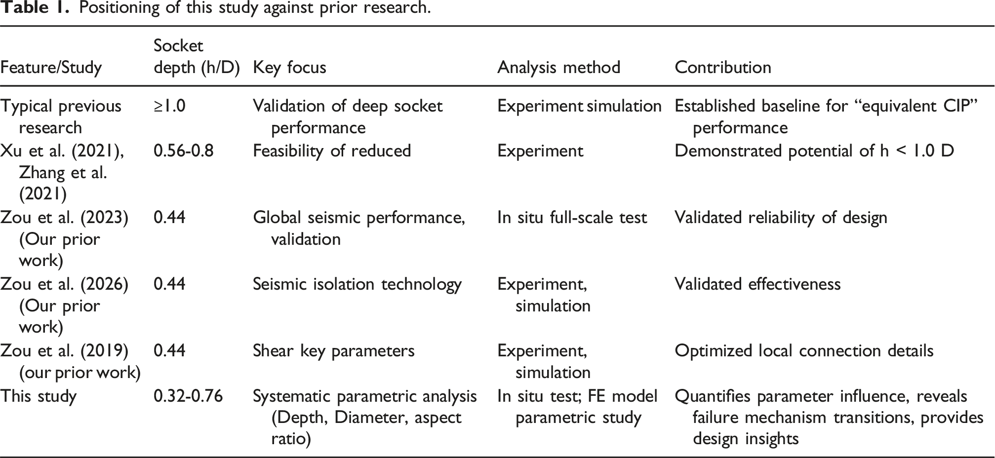
Positioning of this study against prior research.
Quasi-static testing
The test specimen is a double-column shallow socket pier from the Zhengzhou-Jinan high-speed railway. The in-situ full-scale test, including specimen fabrication, detailed test setup, instrumentation, data acquisition, loading protocol, and observed failure modes, has been comprehensively described in a prior publication (Zou et al., 2023). For brevity and to avoid duplication, this section provides an overview of the test, and the reader is referred to the aforementioned paper for complete experimental details. The reader is referred to that study for an in-depth analysis. The present study leverages this validated model primarily for parametric investigation, as discussed in the following sections.
Specimen description
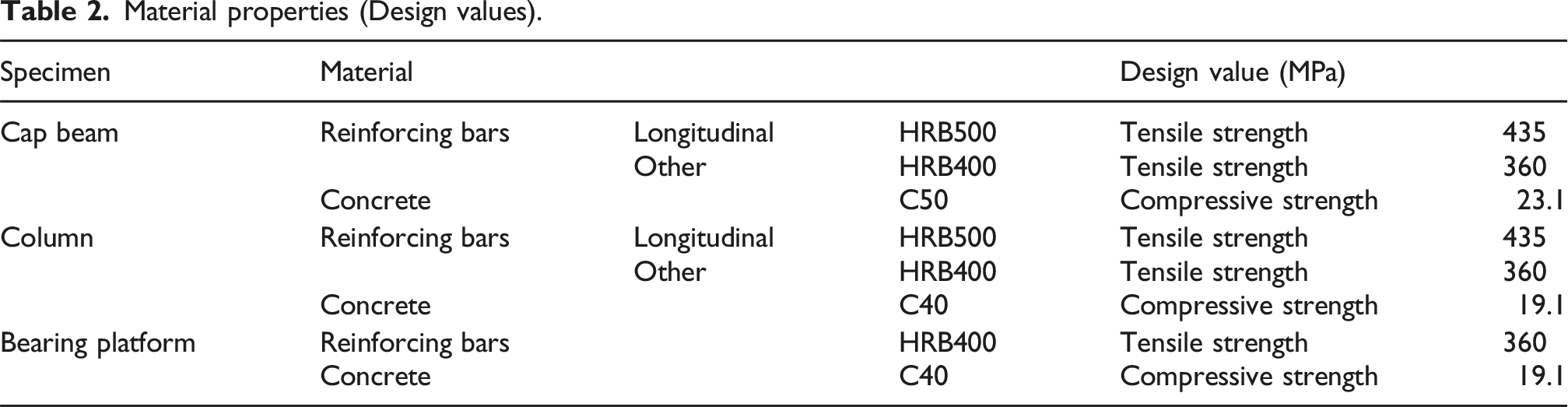
The test specimen is a double-column shallow socket pier from the Zhengzhou-Jinan high-speed railway, with key dimensions: total height 13.5 m, column outer diameter 2.7 m, wall thickness 450 mm, and socket depth 0.44D (Figure 1). Detailed geometry and construction are described in Zou et al. (2023). Material properties (design values) are summarized in Table 2; actual measured properties from Zhang et al. (2024); Zou et al. (2023) were used in FE analysis. Key dimensions and reinforcement layout of the shallow socket pier (in mm). Material properties (Design values).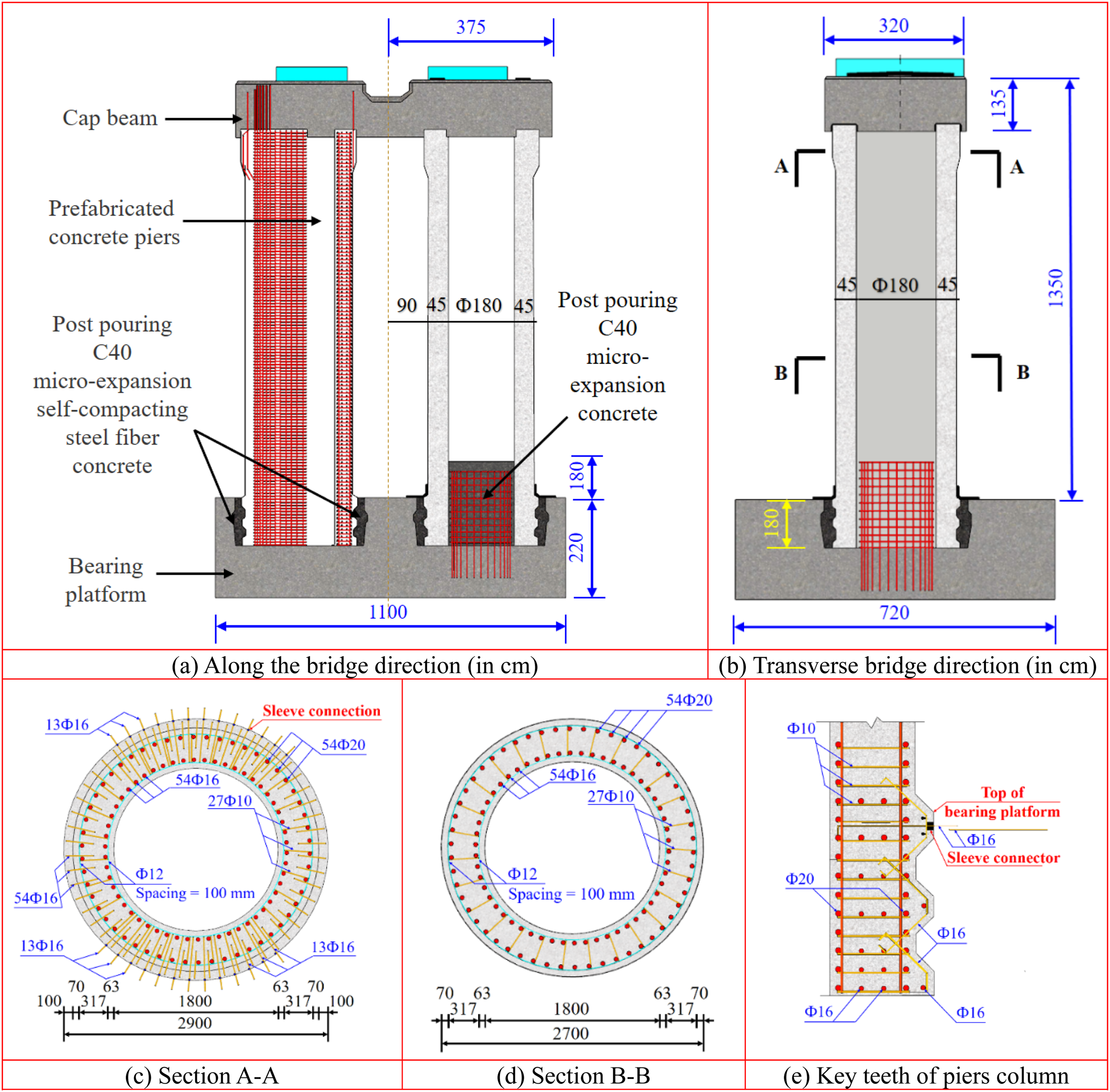
Test setup and loading protocol
Figure 2 shows the test setup. Vertical loads (1346 t total) simulated superstructure mass, applied via hydraulic jacks. Horizontal cyclic loading followed a force-controlled protocol with an initial step size of 100 kN, adjusted based on specimen response. Displacement was monitored at the cap beam center. Layout of test site.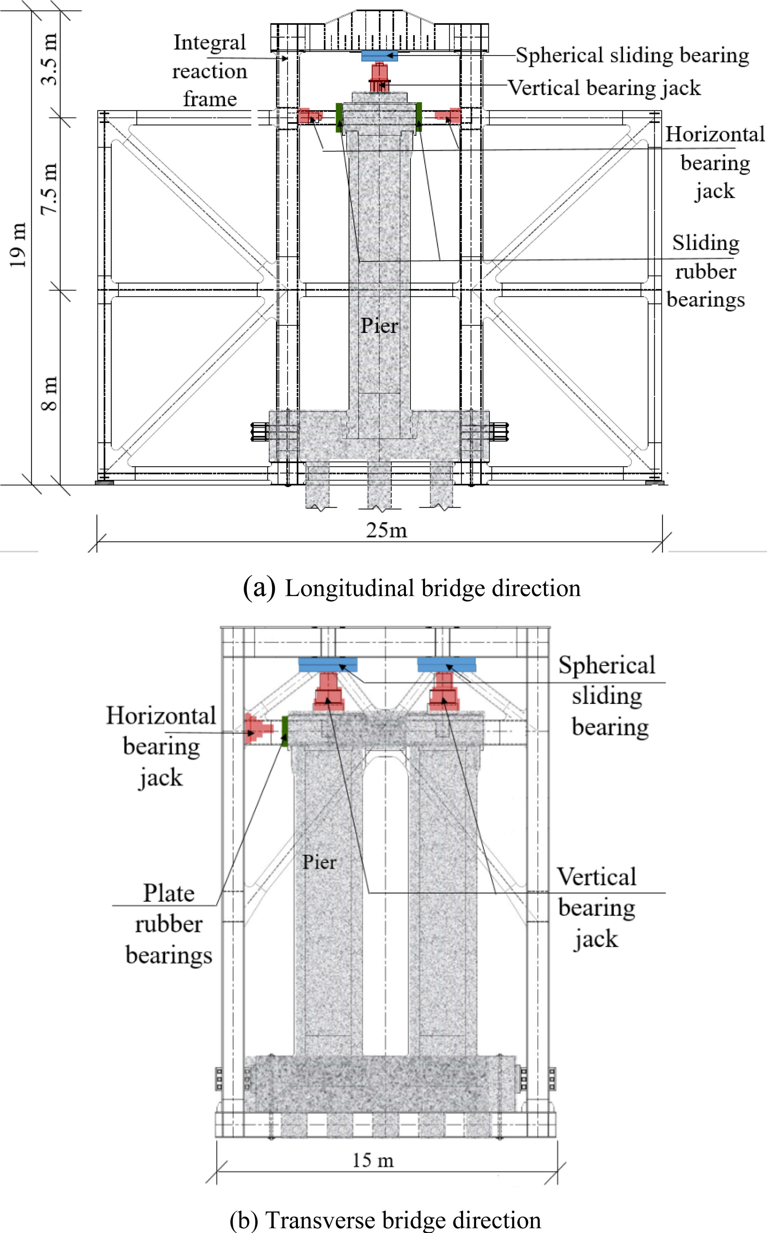
Analytical study
Model description
In ABAQUS software, finite element analysis models of the cap beam, pier column, bearing platform, and post-pour parts were created using solid elements. The model development, calibration, and validation are detailed in Zou et al. (2019), including element types (C3D8R, T3D2), mesh strategy, material models (Concrete Damaged Plasticity for concrete, bilinear for steel), interaction properties (friction coefficient μ = 0.8), and boundary conditions.
Material properties
The concrete damaged plasticity (CDP) model in ABAQUS was employed to simulate the nonlinear behavior of concrete. The input parameters for the CDP model (compressive and tensile stress-strain curves) were derived from the measured material properties referenced in the specimen description (Zou et al., 2023). Similarly, the elastic-plastic bilinear model for steel reinforcements used the measured yield strength, tensile strength, and elastic modulus from the same source. This ensures the simulation reflects actual pier behavior, not just conservative design strengths.
Elements and finite element mesh
The pier cap beam, columns, post-pouring parts, and bearing platforms are simulated using an eight-node linear reduced integral solid element, C3D8R. The reinforcements utilize a two-node linear three-dimensional truss element, T3D2. Each entity is meshed using a structured grid partitioning strategy. The unit shapes of the pier cap beam, columns, and pier cap are meshed with a hexahedral mesh.
The contact between the inner surface of the model’s post-pouring part and the side surface of the pier column was defined as a binding contact. Given the minor bond slip between the steel skeleton and concrete, the steel truss elements in the model are embedded into the concrete solid elements in a “built-in” manner.
In order to consider the squeezing, detachment, and relative sliding among the socket connection components, the contact properties in the normal and tangential directions on the contact surface are defined distinctly. The normal direction interaction is specified as a “hard” contact, effective only under compression, not under tension. The tangential direction employs a “penalty” function friction model to simulate sliding behavior between contact surfaces. A friction coefficient of μ = 0.8 was adopted for the roughened concrete-concrete interface. This friction coefficient (μ = 0.8) corresponds to the shear-friction factor specified for construction joints in concrete design codes. It aligns with Clause 11.1.9 of the Chinese code GB 50,010-2010 (GB 50010-2010, 2010). For comparison, ACI 318-19 (Table 22.9.4.2) provides shear-friction coefficients ranging from 0.6 to 1.0 based on interface roughness, with 1.0 representing a fully roughened surface. The value of 0.8 is therefore conservative relative to ACI’s upper bound and is appropriate for the intentionally roughened socket interface in this study. This choice was validated through calibration against experimental hysteresis data.
The base of the bearing platform is fully fixed. A loading point is established at the center of the pier cap beam’s top and is coupled with the top surface of the pier cap beam. A constant vertical load of 1346 t is applied along the coupling point of the pier cap beam top. A horizontal force load is also applied at this point. The loading system is the same as the experimental loading system.
The nonlinear quasi-static analysis was performed using the ABAQUS/Standard implicit dynamic solver. This approach is particularly suitable for problems involving complex contact, material nonlinearity, and potential instabilities where standard static solvers may encounter convergence difficulties. To ensure the dynamic implicit analysis truly represented a quasi-static response, a sufficiently slow, constant displacement rate was applied. The horizontal loading was applied at a rate of 0.1 mm/s. At this rate, the time required to complete a full loading cycle (e.g., to the maximum displacement of 56 mm) is 560 seconds, which is approximately 1000 times longer than the estimated fundamental period of the pier (approximately 0.55 seconds). Consequently, the resulting accelerations and inertial forces are negligible compared to the internal structural forces, confirming that the analysis effectively captures quasi-static behavior. This methodology is consistent with established practices for simulating quasi-static response in ABAQUS for complex nonlinear problems (Wu et al., 2025; Zhang et al., 2024; Liu et al., 2025).
Calibration of the FE model
Figure 3 compares the experimental and simulated hysteresis curves. The simulation captures the key features of the response, including the pinching effect and overall loop shape. At the reference displacement of 56 mm, the simulated peak loads (3380 kN and −3286 kN) are within 0.59% and 2.26% of the experimental values (3400 kN and −3362 kN), confirming the model’s accuracy in predicting the force-displacement behavior. Hysteretic curves of shallow socket bridge pier column.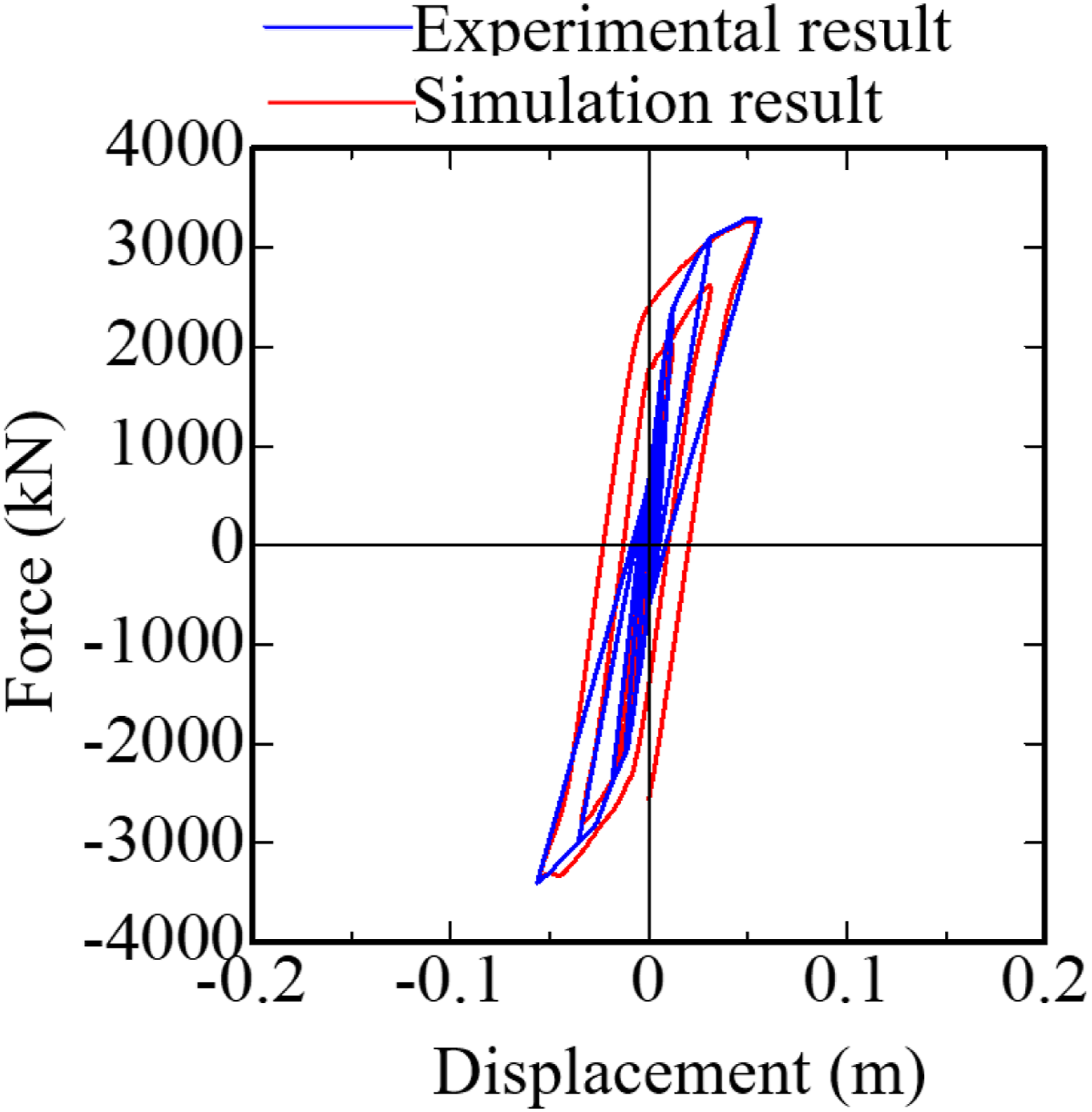
Quantitative validation and discussion on uncertainties
The close agreement between the experimental and numerical hysteresis curves (Figure 3) and the minimal error in peak load (0.59% and 2.26%) provide initial validation of the FE model. To further substantiate the model’s accuracy and address potential uncertainties, a more detailed quantitative comparison was conducted.
Quantitative error analysis
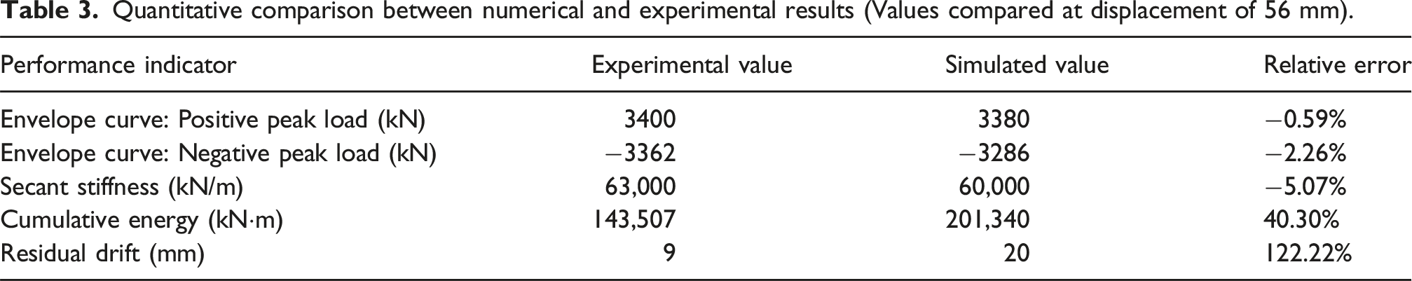
A quantitative comparison of key seismic performance indicators was conducted at a horizontal displacement of 56 mm, corresponding to the stage of first peak load attainment in the test. The relative error for each indicator is defined as:
Quantitative comparison between numerical and experimental results (Values compared at displacement of 56 mm).
Despite these discrepancies in energy dissipation and residual displacement, the model successfully captures the overall hysteresis loop shape, progressive stiffness degradation, and evolution of damage patterns observed experimentally (Figure 3). Consequently, the validated model is deemed well-suited for the subsequent parametric analysis, the objective of which is to identify comparative trends and failure mechanisms influenced by design parameters, rather than to achieve precise cycle-by-cycle replication.
Discussion on modeling uncertainties and parameter sensitivity
Despite the excellent quantitative agreement, it is important to discuss potential sources of uncertainty inherent in the modeling approach.
Minor discrepancies or experimental uncertainties can be attributed to: (1) The inherent variability in the material properties of concrete. (2) The idealized fully fixed boundary condition in the simulation, which might not perfectly replicate the actual soil-structure interaction.
Predictions of numerical modeling uncertainties are subject to simplifications: (1) The concrete damage plasticity model parameters were selected based on typical literature values. (2) The interface behavior was defined by a constant friction coefficient.
Design parameter analysis
In order to examine the impact of key design factors like socket depth, pier diameter, and aspect ratio on the seismic performance of socket bridge piers, models of both CIP integral and socket bridge piers are designed for quasi-static analysis.
Socket depth
The effect of socket depth on the seismic performance of shallow socket bridge piers is investigated by maintaining constant the height of the pier platform and the pier column above the pier bearing platform while progressively increasing the socket depth by raising the embedded height of the pier column in the pier bearing platform. Models of shallow socket bridge piers with socket depths of 0.32 D, 0.44 D (test pier), 0.6 D, 0.7 D, and 0.76 D were established for quasi-static analysis.
Hysteretic curves
Hysteresis curves for piers with different socket depths are compared in Figure 4(a). While the overall loop shapes are similar, deeper sockets delay the attainment of the ultimate load and result in a more gradual post-peak strength degradation. Figure 4(b) displays the cumulative hysteresis energy dissipation curves of shallow socket bridge piers with varying socket depths. Cumulative energy rises rapidly with displacement, but socket depth has a minimal impact. The impact of socket depth on the cumulative energy consumption of these piers is not pronounced. When the horizontal displacement reaches 766 mm, the cumulative hysteresis energy consumption of the bridge pier with a socket depth of 0.32 D is only 11.4% higher than that of the pier with a socket depth of 0.76 D. Figure 4(c) illustrates the residual displacement curves of shallow socket bridge piers with different socket depths, suggesting that an increase in socket depth has a minimal effect on the residual displacement of these bridge piers. Hysteresis performances of shallow socket bridge piers under different socket depths.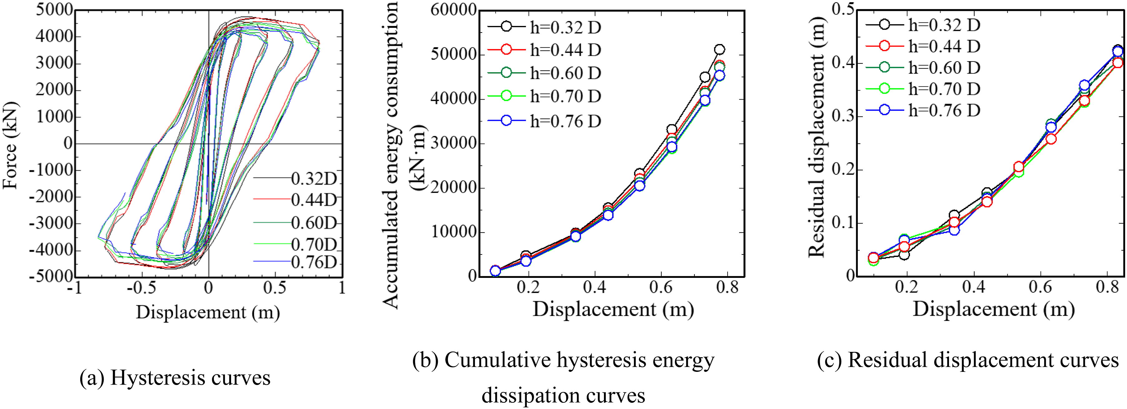
Skeleton curves
Figure 5(a) depicts the skeleton curves of shallow socket bridge piers with varying socket depths, with key indicators summarized in Table 4. Comparing overall trends reveals that the rising sections of these curves are nearly identical, even as socket depth increases from 0.32 D to 0.76 D. The initial stiffness remains largely constant, varying by no more than 12.5%. Skeleton curves and equivalent stiffness degradation for piers with different socket depths. Summary of key seismic performance parameters derived from the skeleton curves of bridge piers with varying socket depths.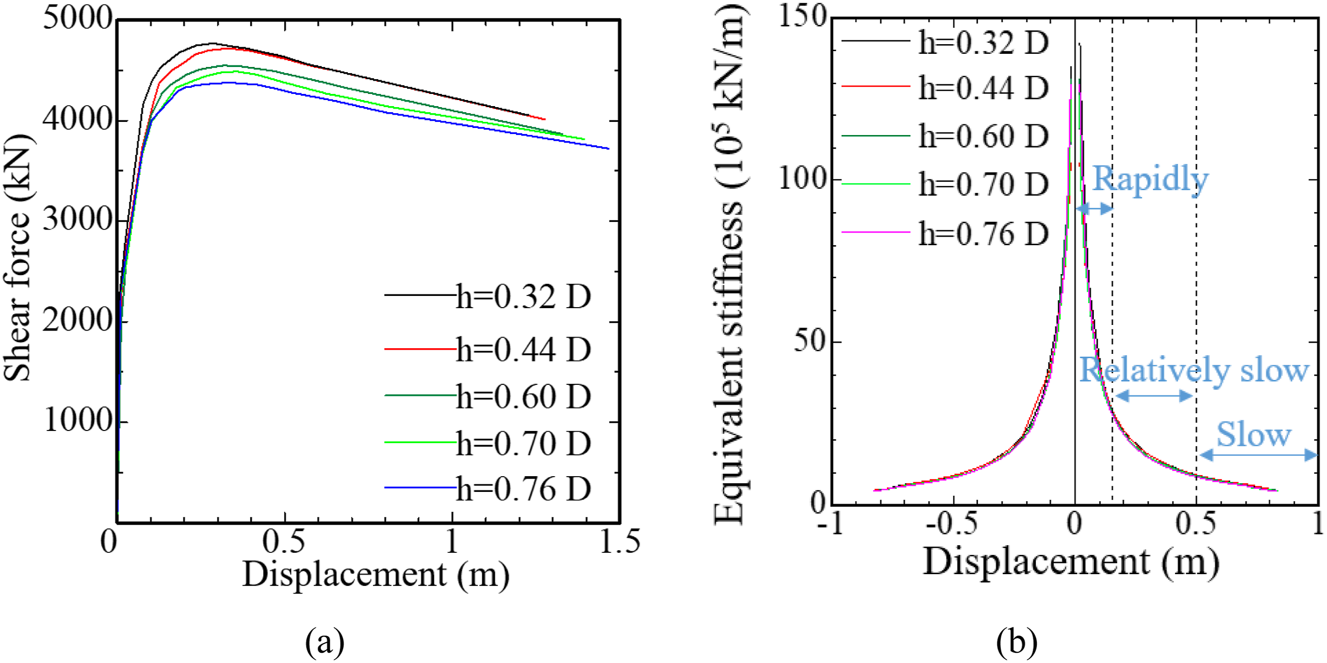
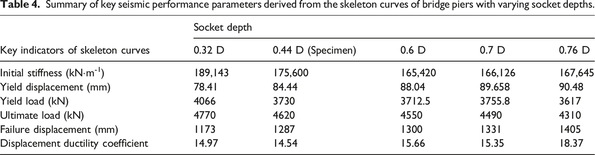
The inflection point position indicates that greater socket depth significantly enhances yield displacement and delays yield failure. This is attributed to increased participation of embedded reinforced concrete in horizontal shear resistance. Increasing socket depth from 0.32 D to 0.76 D reduces the yield load by 11.0% and the peak lateral shear capacity by 9.6%. However, the descending sections become gentler, and failure displacement increases by 19.8%, markedly improving displacement ductility. This improvement can be attributed to the progressive mobilization of the embedded concrete in shear resistance. In piers with shallow sockets, a large portion of the embedded concrete must engage simultaneously under a given shear force, leading to higher initial stiffness and a rapid progression to yielding and peak load. After the peak load is reached, widespread damage results in a sharp stiffness degradation and rapid failure. In contrast, deeper sockets provide a greater volume of embedded concrete. As the shear force increases incrementally, the concrete is mobilized progressively, allowing the resistance to be sustained over a longer deformation range. This continuous mobilization mechanism slightly reduces the initial stiffness and peak load compared to shallower sockets but significantly enhances the failure displacement and ductility.
Thus, greater socket depth substantially enhances the post-peak ductility of socket piers.
Figure 5(b) depicts the equivalent stiffness curves of shallow socket bridge piers with different socket depths. It demonstrates that the equivalent stiffness curves of each pier are generally consistent when the socket depth is varied from 0.32 D to 0.76 D, indicating that socket depth has a minimal influence on the equivalent stiffness of shallow socket bridge piers.
Damage analysis
The Mises stress distributions (Figure 6) illustrate how socket depth governs the failure mechanism. In piers with shallow sockets (e.g., 0.32D), stress develops rapidly and uniformly along the entire embedded length under low loads, engaging most of the socket concrete simultaneously in shear. This leads to a concentration of damage at the socket top, making it the weak link susceptible to shear failure. Conversely, in piers with deeper sockets (e.g., 0.76D), stress progresses gradually from the top downwards, mobilizing the concrete over a larger volume. This shifts the weak link to the pier column itself, where stress localizes in a plastic hinge region at the base—a failure mode analogous to that of cast-in-place integral piers. Thus, increasing socket depth effectively transitions the failure from a brittle socket shear to a ductile column flexure. Mises stress cloud map of pier column with different socket depths (MPa).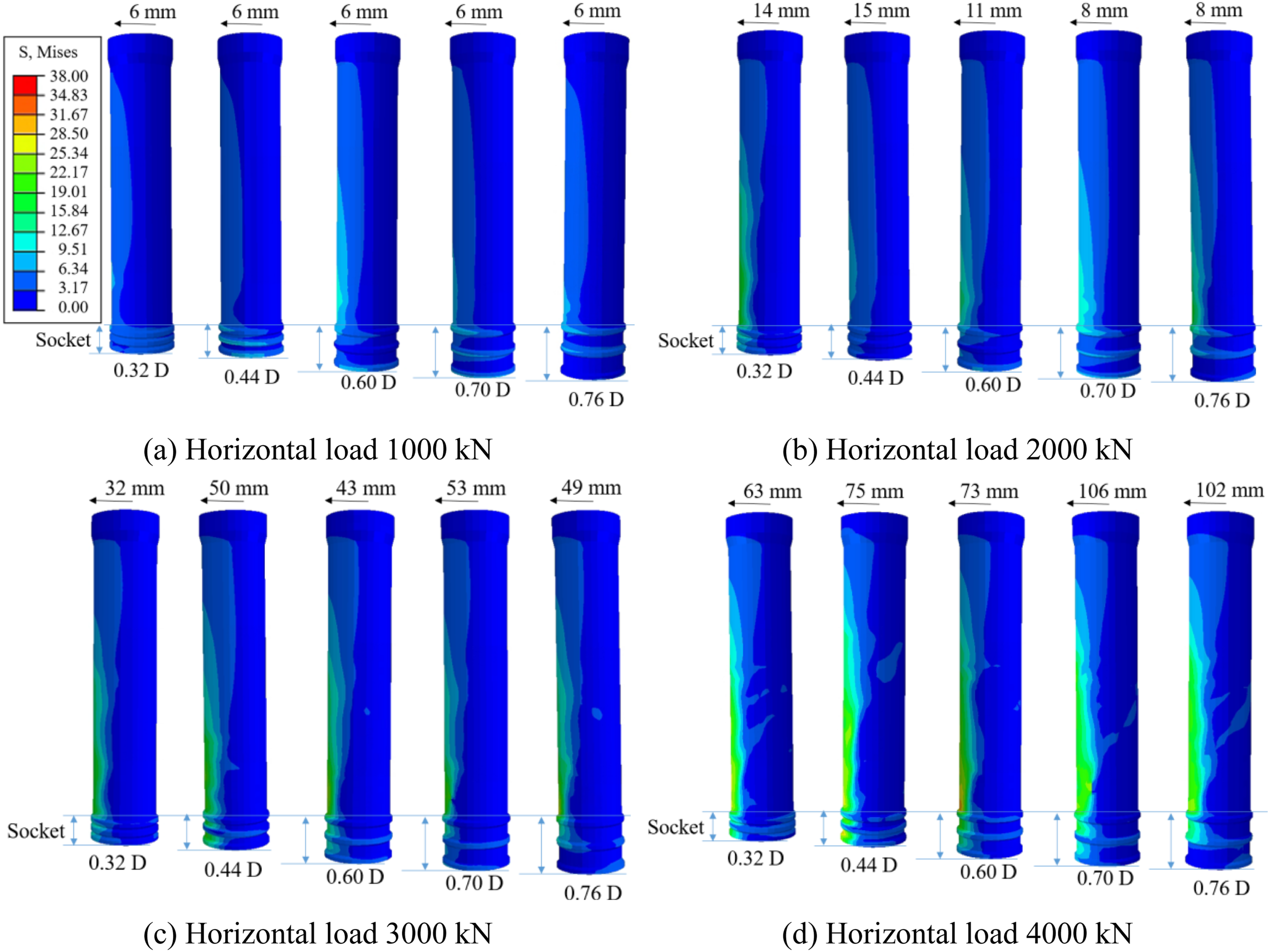
Pier diameter
By altering the pier column’s diameter to examine its influence on the seismic performance of shallow socket bridge piers while keeping the height of both the pier column and bearing platform, as well as the socket depth, constant, models of shallow socket bridge piers with pier diameters of 2.1, 2.4, and 2.7 m were established for quasi-static analysis.
Hysteretic curves
Figure 7(a) illustrates the hysteresis curves at the top load points of the shallow socket bridge piers with varying pier diameters. It indicates a consistent trend in the hysteresis curve across all piers. With a pier height of 13.5 m and a socket depth of 1.2 m, larger pier diameters correlate with increased bearing capacity. Comparison of hysteresis performances of shallow socket bridge piers under different pier diameter.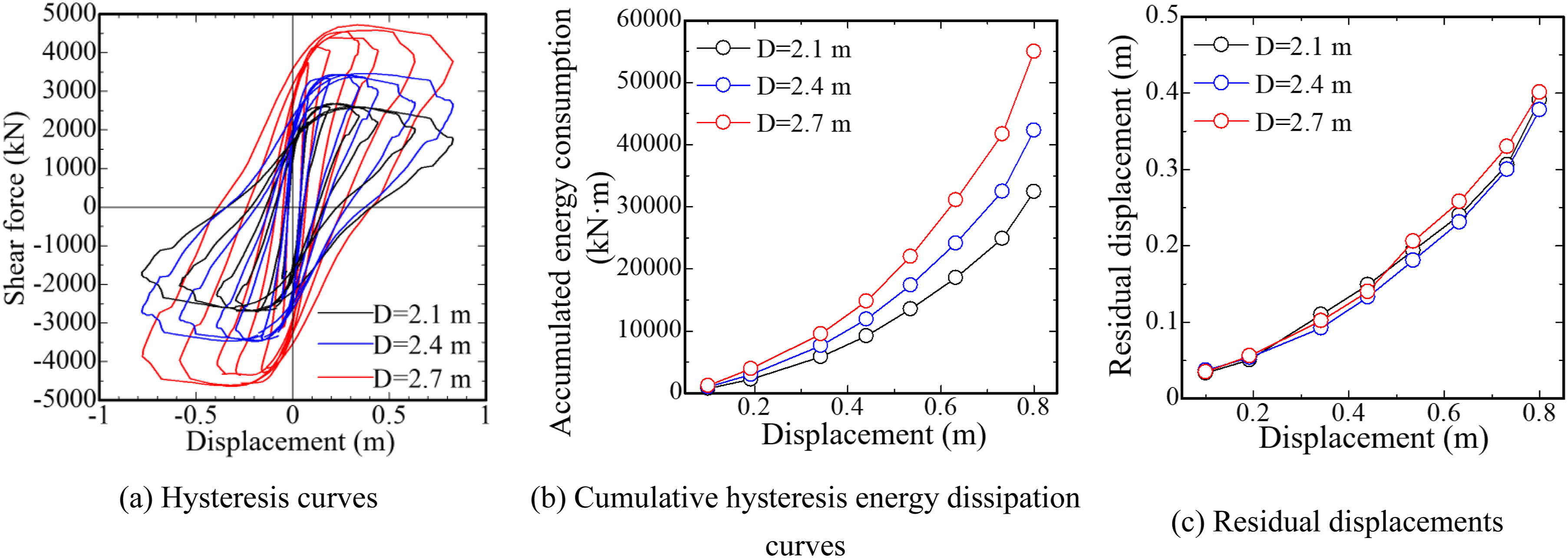
The cumulative hysteresis energy dissipation curves of shallow socket bridge piers with varying pier diameters are depicted in Figure 7(b). These curves reveal a consistent trend in cumulative energy consumption for each pier. At the same socket depth, the energy dissipation capacity of large-diameter shallow socket bridge piers is significantly improved. When the horizontal displacement is 800 mm, compared to the shallow socket bridge pier with a diameter of 2.1 m, the cumulative energy consumption of the pier with a diameter of 2.4 m and that with a diameter of 2.7 m increased by 30.5% and 69.6%, respectively. This increase has no significant effect on the residual displacement of shallow socket bridge piers (Figure 7(c)).
Skeleton curves
Figure 8(a) displays the skeleton curves of shallow socket bridge piers with different diameters. The key indicators of these curves are listed in Table 5. Analysis of the skeleton curves shows that increasing the pier column diameter from 2.1 to 2.7 m enhances the initial stiffness of the bridge pier by 147.2%. This increase in pier column diameter substantially boosts the lateral stiffness of the shallow socket bridge pier. Larger section socket bridge piers exhibit more significant elastic deformation, with a peak load increase of 71.7%. This indicates a high safety margin for these piers as diameter increases, primarily because larger diameter enhances column stiffness and thus load-bearing capacity. Skeleton curves and equivalent stiffness degradation for piers with different diameters. Summary of key seismic performance parameters derived from the skeleton curves of bridge piers with varying pier diameters.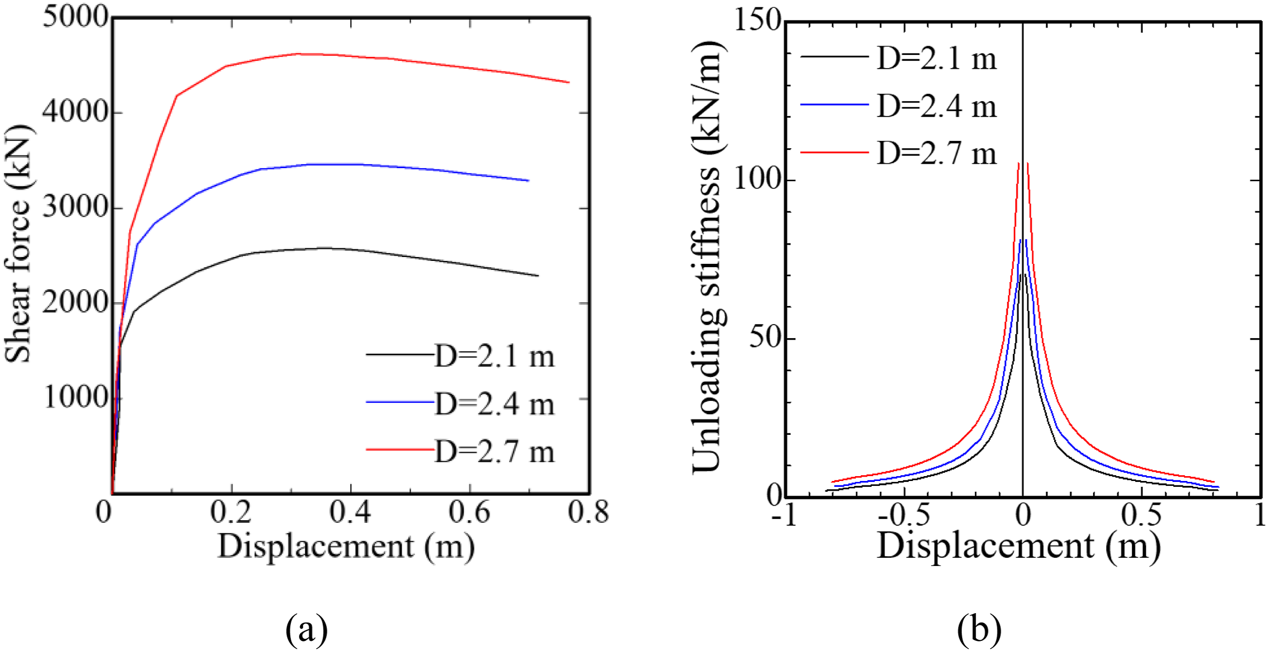
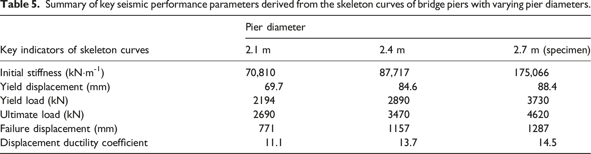
Figure 8(b) presents the equivalent stiffness curves of shallow socket bridge piers with different diameters. As indicated, each shallow socket bridge pier shows a similar stiffness degradation trend. The larger the pier diameter, the higher the equivalent stiffness of the shallow socket bridge pier. However, the maximum disparity in equivalent stiffness when the pier column diameter increases from 2.1 to 2.7 m is only 1.7%. Hence, the impact of pier column diameter on the equivalent stiffness of shallow socket bridge piers is relatively minor.
Damage analysis
Figure 9 illustrates the Mises stress cloud map of a shallow socket bridge pier column with various socket depths. The figure shows that increasing the pier diameter from 2.1 to 2.7 m significantly reduces both the displacement at the pier top along the bridge direction and the stress in the bridge pier column. This reduction is mainly attributed to the increased stiffness of the bridge pier body with larger diameters, which effectively enhances the overall stiffness of the shallow socket pier. Consequently, this limits the development of pier top displacement and reduces the stress in the bridge pier column. Mises stress cloud maps (MPa).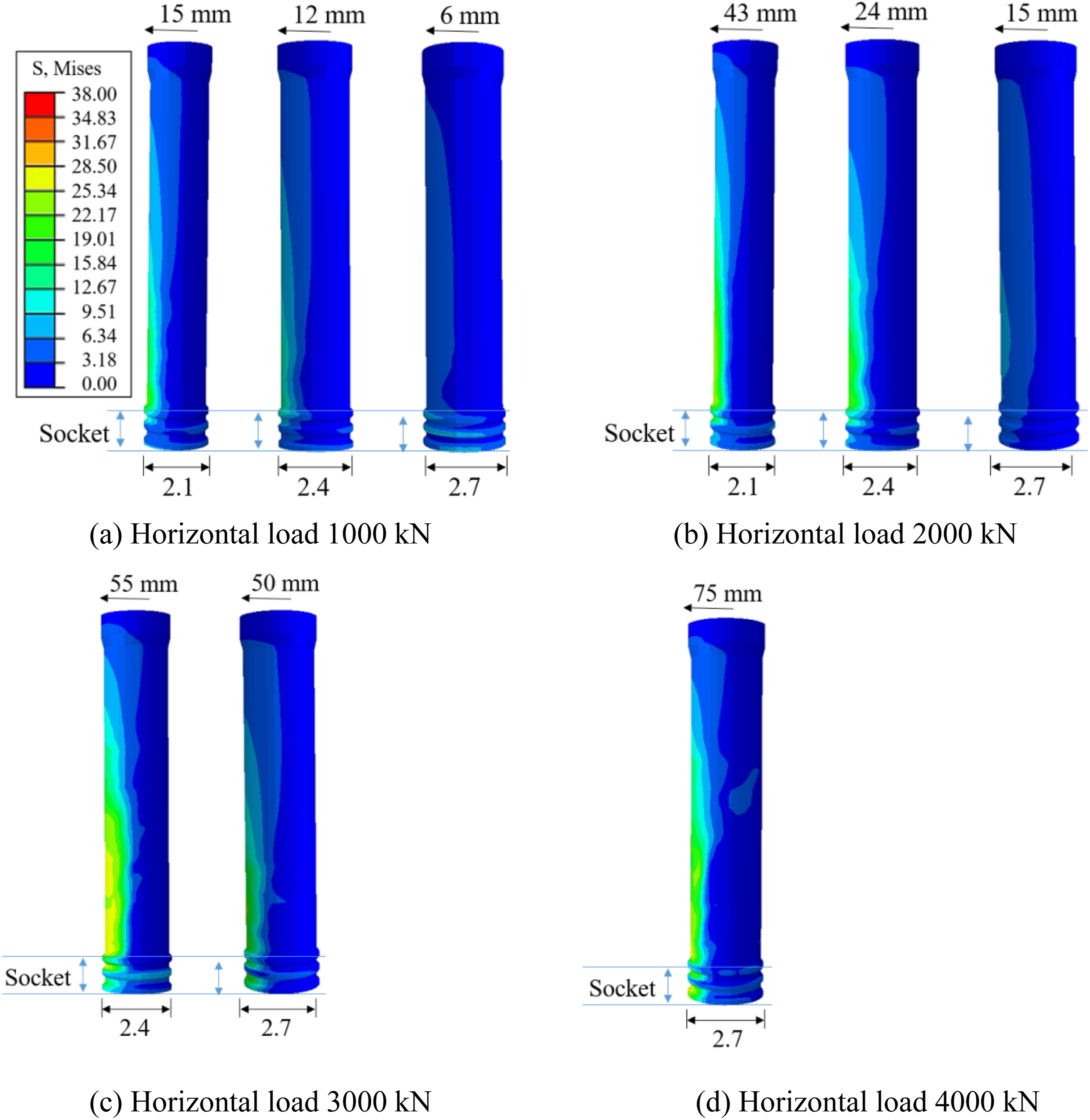
The damage analysis of the bridge piers reveals that increasing the pier column diameter leads to different failure modes in shallow socket bridge piers with identical socket depths. For a shallow socket bridge pier with a 2.1 m diameter, damage primarily occurs at the bottom of the pier column, predominantly through bending. Conversely, for a pier with a 2.7 m diameter, damage is concentrated both at the bottom of the pier column and in the socket part, with bending damage at the pier column bottom and bending shear damage at the socket connection. This indicates that as the pier column diameter of shallow socket bridge piers increases, the strength of the bridge pier columns improves considerably, causing the weak region of the bridge pier to shift from the pier column to the socket connection part. Therefore, while increasing the diameter of shallow socket bridge piers enhances their load-bearing capacity, maintaining the same socket depth may lead to shear failure at the socket connection.
Aspect ratio
In order to investigate the impact of aspect ratio on the mechanical properties of shallow socket bridge piers, only the height of the pier columns above the bearing platform or the pier column’s diameter were altered in the initial model, keeping all other conditions identical to the pier specimen described in Chapter 2. The aspect ratios of the 7 models are 2, 3, 4, 5, 5.6, 6.4 and 8.
Hysteretic curves
The simulated hysteresis curves for 7 models with varying aspect ratios are presented in Figure 10(a). This figure illustrates that the aspect ratio markedly affects the hysteresis behavior of these prefabricated bridge piers. Altering the aspect ratio of the pier columns significantly changes the shape of their hysteresis loops. Comparison of hysteresis performances.
As the aspect ratio of the pier column increases, the horizontal bearing capacity of the shallow socket bridge pier diminishes notably, and the hysteresis loop becomes progressively less pronounced, exhibiting a bidirectional “pinching”. This indicates a substantial change in the hysteresis energy dissipation capacity of the pier. Conversely, reducing the aspect ratio results in shorter column-like piers, which enhances stability and improves both their bearing capacity and the robustness of their hysteresis curves.
Figure 10(b) displays the cumulative hysteresis energy consumption curves for each pier with varying aspect ratios. It reveals a significant decrease in the cumulative energy consumption of shallow socket bridge piers as the aspect ratio increases. For instance, with an aspect ratio of 2, the cumulative energy consumption is 287,079 kNm, approximately 92.3% higher than that of a pier column with an aspect ratio of 8.
Figure 10(c) shows that the residual displacement of shallow socket bridge piers diminishes as the pier aspect ratio increases. Specifically, increasing the aspect ratio from 2 to 8 reduces the residual displacement of the piers from 545 to 265 mm, a decline of 51.4%. This reduction in residual deformation weakens the plasticity of the piers and lessens the energy dissipation capacity of the shallow socket bridge pier.
Skeleton curves
Figure 11(a) illustrates the skeleton curves for each shallow socket bridge pier with varying aspect ratios. Table 6 summarizes the characteristic points of these curves. An increase in the aspect ratios of the shallow socket bridge piers, from 2 to 8, correlates with a 91.3% reduction in their initial stiffness. This decrease in stiffness is mainly due to the increased flexibility of piers with higher aspect ratios under external loads, which amplifies their response and results in a reduced initial slope of the skeleton curves. Skeleton curves and equivalent stiffness degradation for piers with different aspect ratios. Summary of key seismic performance parameters derived from the skeleton curves of bridge piers with varying aspect ratios.
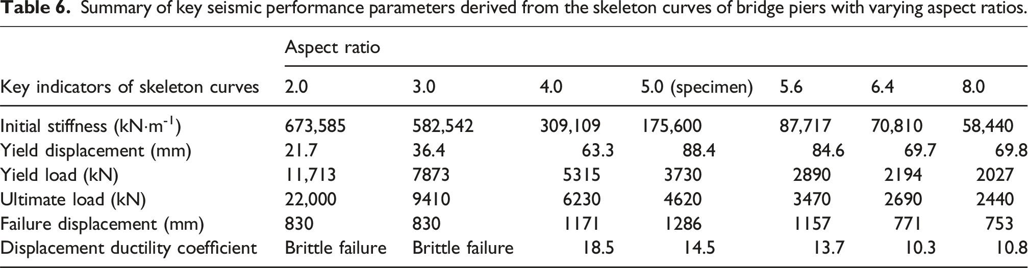
Furthermore, the escalation in the aspect ratio from 2 to 8 led to an 82.7% decline in yield strength and a 22.7% rise in yield displacement of the bridge piers. This trend occurs because the bearing capacity of the pier body diminishes as the aspect ratio increases, leading to significant horizontal displacement or damage under relatively small forces.
Upon reaching the ultimate load, shallow socket bridge piers with aspect ratios of 2 and 3 undergo brittle failure, abruptly losing their horizontal bearing capacity. Conversely, piers with aspect ratios of 4, 5, and 8, after peaking in horizontal bearing capacity, transition into the plastic stage, where the horizontal force diminishes with increasing displacement. Additionally, the displacement ductility coefficient decreases as the pier aspect ratios increase.
Figure 11(b) displays the equivalent stiffness curves of shallow socket bridge piers with different aspect ratios. It indicates that the aspect ratio significantly influences the piers’ equivalent stiffness. Piers with larger aspect ratios exhibit lower horizontal equivalent stiffness, and their stiffness degradation rate decreases as horizontal displacement grows.
Damage analysis
Figure 12 presents the Mises stress cloud map for shallow socket bridge piers with various aspect ratios. This comparison reveals the aspect ratio’s substantial effect on stress distribution and failure modes in these piers. Mises stress cloud maps (MPa).
When pier diameter and shallow socket depth are identical, a smaller aspect ratio results in greater stiffness. Under the same horizontal load, this translates to lesser horizontal displacement at the top of the pier and reduced stress on it. Excessive horizontal displacement not only escalates stress on the pier column but also on the socket connection.
The aspect ratio influences the structural failure mode. With smaller ratios, the stiff shallow socket bridge pier columns make the socket connection the weak point, leading to brittle failure in the upper layer of reinforced concrete at the socket. Conversely, with larger ratios, the pier column becomes the weak point due to reduced stiffness, resulting in bending failure at the plastic hinge area at the column’s base. Therefore, designing an optimal stiffness distribution ratio between the pier column and the socket is crucial to avoid brittle failure, prevent the socket section from becoming the bridge pier’s weakest part, and circumvent construction challenges and cost overruns due to oversized, high-strength socket sections.
Conclusions
In this study, the shallow socket double-column hollow bridge pier of the Zhengji high-speed railway serves as the prototype. The research completes the in situ full-scale quasi-static test of the bridge pier. Finite element numerical simulations are conducted using ABAQUS software, and the influence of socket depth, pier diameter, and aspect ratio on the seismic performance of shallow socket pier by a comprehensive parametric analysis, has quantified the influence of socket depth, pier diameter, and aspect ratio on the seismic performance of shallow socket piers. The main conclusions are: (1) The finite element model, validated against in situ full-scale quasi-static tests of a shallow socket double-column hollow bridge pier, accurately predicts hysteretic behavior. (2) The concept of “CIP equivalence” was investigated and confirmed through comparative numerical analysis. Key findings from the parametric study, which compared the seismic performance of socket piers against a CIP benchmark model, are as follows:
The hysteretic curve of the shallow socket bridge pier (0.44 D) closely resembles that of the CIP integral bridge pier in the numerical simulation, with both exhibiting robust energy dissipation capacity.
The numerical models reveal that both pier types develop plastic hinges in the pier column through continuous stress transfer. While damage in CIP piers is concentrated at the pier base, shallow socket piers experience damage at both the pier base and the socket connection. Nevertheless, the primary failure mode remains flexural, confirming the reliability of the shallow socket connection interface.
The study further establishes that with increasing socket depth (e.g., to 0.76D), the mechanical behavior of the socket pier converges more closely to that of the CIP pier, particularly in terms of enhanced post-peak ductility. (3) Socket depth has a minimal influence on the hysteretic performance but significantly governs the failure mode. A shallower depth reduces the bearing capacity and promotes shear failure, whereas a greater depth substantially enhances post-peak ductility, resulting in a 22.7% increase in the displacement ductility coefficient. (4) Increasing pier diameter enhances socket pier performance: energy dissipation capacity increases by 69.6% and ultimate bearing capacity by 71%. However, it shifts stiffness distribution, transferring the weak point from the pier column to the socket connection. Excessively large diameters risk inducing shear failure at this connection. (5) Increased aspect ratio dramatically impairs seismic performance: initial stiffness decreases by 91.3%, peak bearing capacity by 88.9%, and cumulative energy dissipation by 92.3%. Aspect ratio variations alter stiffness distribution between pier column and socket, shifting the weak point and determining failure mode. The stiffness distribution ratio must be judiciously designed to prevent brittle failure and avoid construction/cost issues from overly robust socket regions. (6) While analysis employed in situ full-scale specimens, the limited specimen dimensions constrained the range of design parameters investigated. Future work will expand the parameter analysis scope.
Footnotes
Acknowledgments
The research described in this paper was financially supported by the National Natural Science Foundation of China (52222807) and (52308487), and China Railway Group Limited R&D Program (2023-Key-07); China Railway Engineering Design and Consulting Group Co., Ltd. R&D Program (Yan 2022-5, Yan 2023-5, KY2024A004, KY2024A029). Young Talent Support Project of Guangzhou Association for Science and Technology (QT-2025-007), The Guangdong Basic and Applied Basic Research Foundation (No.2022A1515110191; 2023A1515011914).
Author contributions
All authors contributed to the study conception and design. The experiment was completed by all authors. material preparation, data collection and analysis were performed by Ningjun Zhang and Chenglong Hu. The first draft of the manuscript was written by Ningjun Zhang and all authors commented on previous versions of the manuscript. All authors read and approved the final manuscript.
Funding
The authors disclosed receipt of the following financial support for the research, authorship, and/or publication of this article: This work was supported by Young Talent Support Project of Guangzhou Association for Science and Technology (QT-2025-007), The Guangdong Basic and Applied Basic Research Foundation (2023A1515011914, No.2022A1515110191), China Railway Engineering Design and Consulting Group Co., Ltd. R&D Program (KY2024A004, KY2024A029, Yan 2022-5, Yan 2023-5), China Railway Group Limited R&D Program (2023-Key-07), National Natural Science Foundation of China (52222807, 52308487).
Declaration of conflicting interests
The authors declared no potential conflicts of interest with respect to the research, authorship, and/or publication of this article.
Data Availability Statement
The datasets generated during and/or analysed during the current study are available from the corresponding author on reasonable request.