
Abstract
This study experimentally investigates the axial compressive behavior of 10 square high-strength fully recycled aggregate concrete-filled steel tube (HSFRACFT) columns, focusing on the effects of concrete strength and length-to-width ratio on failure modes, load-displacement responses, and load-bearing capacity. The results indicate that both stub and slender columns experience brittle failure. Poor ductility and composite effect were observed for the present test which has a confinement factor of 0.31≤ ξ ≤ 0.42. A numerical parametric study was carried out to examine the effects of concrete strength, steel yield strength, and width-to-thickness ratio on the axial behavior of square HSFRACFT columns. Results showed that increasing the confinement factor enhances the ductility but hardly improves overall composite strength. It is recommended to incorporate additional confinement measures, such as internal spiral stirrups or tie rods, in the practical application of square HSFRACFT columns. Finally, an axial load-bearing capacity model of HSFRACFT columns was developed and validated based on experimental data.
Keywords
Introduction
Recycled aggregate concrete (RAC) (Ozbakkaloglu et al., 2018; Xiao et al., 2018) not only alleviates the imbalance between supply and demand for natural aggregates, but also facilitates the recycling of construction waste (Zhang et al., 2019), making it a green and sustainable material. However, existing studies have shown that the mechanical properties and durability of RAC are inferior to those of conventional concrete (Hansen, 1986; Liu et al., 2020; Richardson et al., 2009; Xu et al., 2019), primarily due to the higher porosity and inherent defects of recycled coarse aggregate (RCA). Consequently, despite its environmental benefits, the practical application of RAC remains limited. To address these issues, high-strength fully recycled aggregate concrete (HSFRAC), comprising 100% recycled coarse aggregate, has been developed. Owing to its relatively high mortar strength, HSFRAC can better confine the RCA, mitigating its internal defects and thereby enhancing the mechanical properties of the concrete. Moreover, the higher density of HSFRAC contributes to improved durability compared to conventional strength RAC. In addition, the use of 100% RCA maximizes the waste recycling. Therefore, HSFRAC has emerged as a promising green and sustainable construction material. However, Liu et al. (2024). Pointed out that HSFRAC exhibits pronounced brittleness. Encasing HSFRAC in steel tube to form HSFRAC-filled steel tube (HSFRACFT) columns may alleviate its brittleness and thereby facilitate broader structural applications.
Square recycled aggregate concrete-filled steel tube (RACFT) columns, owing to their simple beam-column connections, favorable mechanical properties, and ease of construction, are increasingly applied in practical engineering (Lin et al., 2021; Xu and Hu, 2025). In recent years, the axial compressive behavior of RACFT columns has been extensively investigated. Lyu et al. (2021), Qiu et al. (2011) and Han and Yang (2006) examined the effects of RCA replacement ratios (0-100%) on the axial compressive behavior of RACFT stub columns. Their findings showed that although RCA incorporation had little effect on failure modes compared to conventional concrete-filled steel tube (CFT) columns, it generally reduced load-bearing capacity. In contrary, Chen, (2011) observed up to 10% increase in the axial compressive capacity of square RACFT stub columns with higher RCA replacement ratios, attributed to enhanced core RAC strength. Zhang et al. (2012) found that both the RCA replacement ratios and the length-to-width ratios had negligible effects on the load-bearing capacity of square RACFT columns. Despite the environmental benefits of RAC, its application in CFT may also introduce potential disadvantages. The higher porosity of RAC may introduce chloride ion into the concrete especially when the recycled aggregate was from coastal or marine structures, which could potentially affect the long-term durability of RACFT structures. Nevertheless, the present study primarily focuses on the mechanical behavior of RACFT columns under axial compression, while durability-related issues remain an important topic for future investigation.
It is noteworthy that the aforementioned studies primarily focused on RACFT columns incorporating normal-strength RAC. Some previous studies also investigated RACFT columns made with high-strength RAC, defined by a cubic compressive strength fcu ≥ 50 MPa in the present study. Niu et al. (2015) examined the axial compressive behavior of square RACFT stub columns incorporating 100% RCA, with fcu = 72.36 MPa. Their results indicated that the load-bearing capacity, ductility and energy dissipation of these columns were slightly superior to those of specimens made with conventional concrete. Yang and Ma (2013) investigated the behavior of RAC-filled stainless steel tube columns, in which RAC has aggregate replacement ratios ranging from 0 to 70% and fcu between 48.5 and 55.7 MPa. Han et al. (2022) conducted both experimental and numerical studies on the effects of the confinement factor and the RCA replacement ratio on the axial compressive behavior of square RAC-filled stainless steel tube stub columns (fcu ≤ 59.5 MPa), and proposed empirical formulas for predicting ultimate strength. Similarly, Zhao et al. (2023) proposed a simplified calculation model incorporating both the steel yield strength and RCA replacement ratio. The RAC used in their study was prepared with a 100% RCA replacement ratio and had a fcu = 56 MPa. In addition, a number of studies have been conducted on fiber-reinforced polymer (FRP)-confined recycled aggregate concrete. For example, Zhang et al. (2023) investigated the flexural behavior of hybrid FRP-concrete-steel hollow beams incorporating recycled aggregate concrete. Chen et al. (2022) examined FRP-confined square compound concrete columns containing recycled concrete lumps. Zhao et al. (2015) systematically studied the stress-strain behavior of FRP-confined RAC.
Research on square high-strength RACFT columns remains limited, with most previous specimens incorporating RAC of relatively low strength (typically f cu ≤ 60 MPa). Moreover, limited attention has been given to slender columns, despite the significant influence of slenderness ratio on structural performance (Liu et al., 2023; Wu et al., 2018; Yang and Han, 2006). For the first time, this study utilizes high-strength fully recycled aggregate concrete with fcu up to 92 MPa, and systematically investigates the axial compressive behavior of stub and slender HSFRACFT columns with varying length-to-width (L/B) ratios. Section 2 presents the experimental program, which includes ten square HSFRACFT columns subjected to axial compression; Section 3 compares and analyzes the mechanical responses of various specimens; Section 4 presents additional parametric analyses, exploring the ductility and composite behavior of square HSFRACFT columns through numerical simulations; Section 5 proposes a predictive model for the axial load-bearing capacity of square HSFRACFT columns and validates its accuracy against previously published data. This study addresses three major limitations in existing research—RAC strength, recycled aggregates replacement ratios, and L/B ratio parameters—providing valuable reference data for engineering design and promoting the practical application of square HSFRACFT columns in structural engineering.
Experimental program
Specimen design
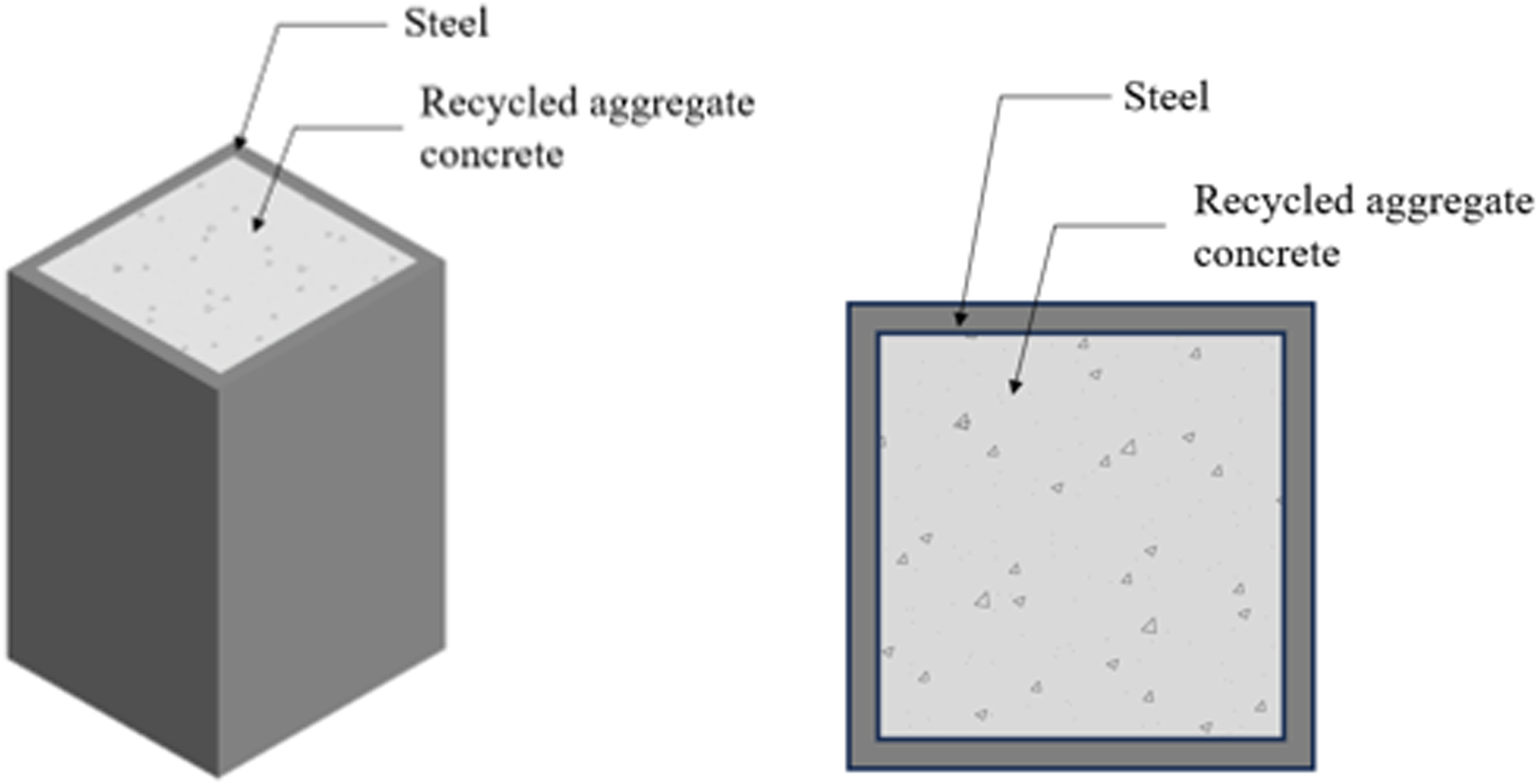
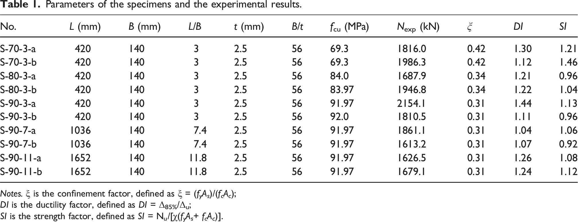
A total of 10 square HSFRACFT columns were designed and fabricated, as shown in Figure 1.The purpose of these specimens was to investigate the effect of HSFRAC strength (fcu = 70 MPa, 80 MPa, 90 MPa) and L/B ratios (L/B = 3, 7.4, 11.8) on the axial compressive behavior. The outer side length B of all specimens was 140 mm, and the steel tube wall thickness t was 2.5 mm. The main design parameters of the specimens for each group are shown in Table 1. In the table, L represents the specimen’s column height, and B/t represents the specimen’s width-to-thickness ratio. Specimens were named as follows: the letter “S” indicates the cross-sectional shape of the specimen is square; the first number after the letter represents the design strength of the RAC, and the second number represents the specimen’s length-to-width ratio. Numbers 3, 7, and 11 represent length-to-width ratios of 3, 7.4, and 11.8, respectively. The letters “a” and “b” denote the first and second specimens with the same parameters, respectively. Structural form of HSFRACFT columns. Parameters of the specimens and the experimental results. Notes. ξ is the confinement factor, defined as ξ = (f
y
A
s
)/(f
c
A
c
); DI is the ductility factor, defined as DI = Δ85%/Δu; SI is the strength factor, defined as SI = Nu/[χ(f
y
A
s
+ f
c
A
c
)].
Materials
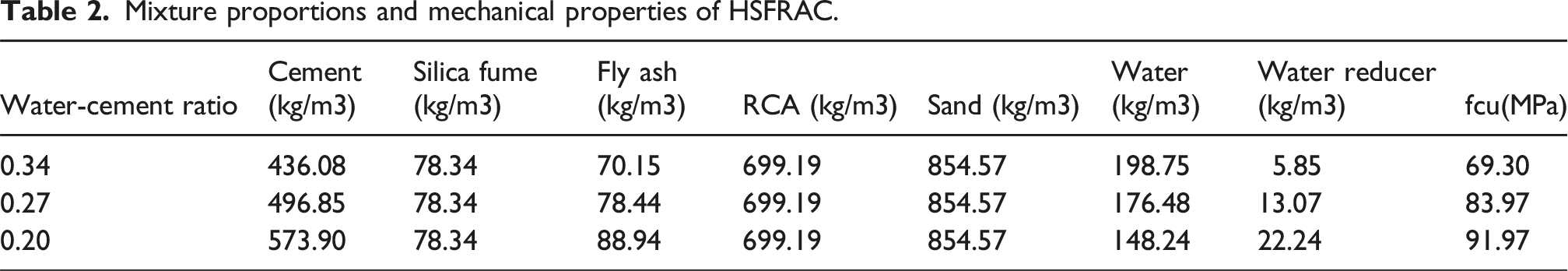
Mixture proportions and mechanical properties of HSFRAC.
Experimental set-up and procedures
The experiments were conducted in the Structural Laboratory of Beijing University of Technology using a 3000 kN electro-hydraulic servo press. The loading setup and measurement point arrangements for both stub columns and slender columns are shown in Figure 2(a) and (b), respectively. A combined load-displacement control method was employed. Initially, a pre-load of 10% of the estimated ultimate load (Pmax) was applied to ensure proper contact between the loading components. The estimated Pmax was calculated in accordance with EC4 (2004) for composite columns using the measured material properties and sectional parameters of the specimens. After pre-loading, the load was removed, and all instruments were reset to zero. The main loading was performed in stages. Up to 0.75 Pmax, the load was incremented by 1/10 Pmax, with each stage held for 2 minutes at a loading rate of 2 kN/s. Between 0.75 Pmax and 0.9 Pmax, increments of 1/15 Pmax were applied, with each stage held for 3 minutes. Beyond 0.9 Pmax, displacement control was used with a rate of 2 mm/min, and the process terminated when the load dropped to 0.7 Pmax. This controlled loading ensured gradual stress application and detailed load-displacement data collection. Test equipment diagram and measurement point distribution.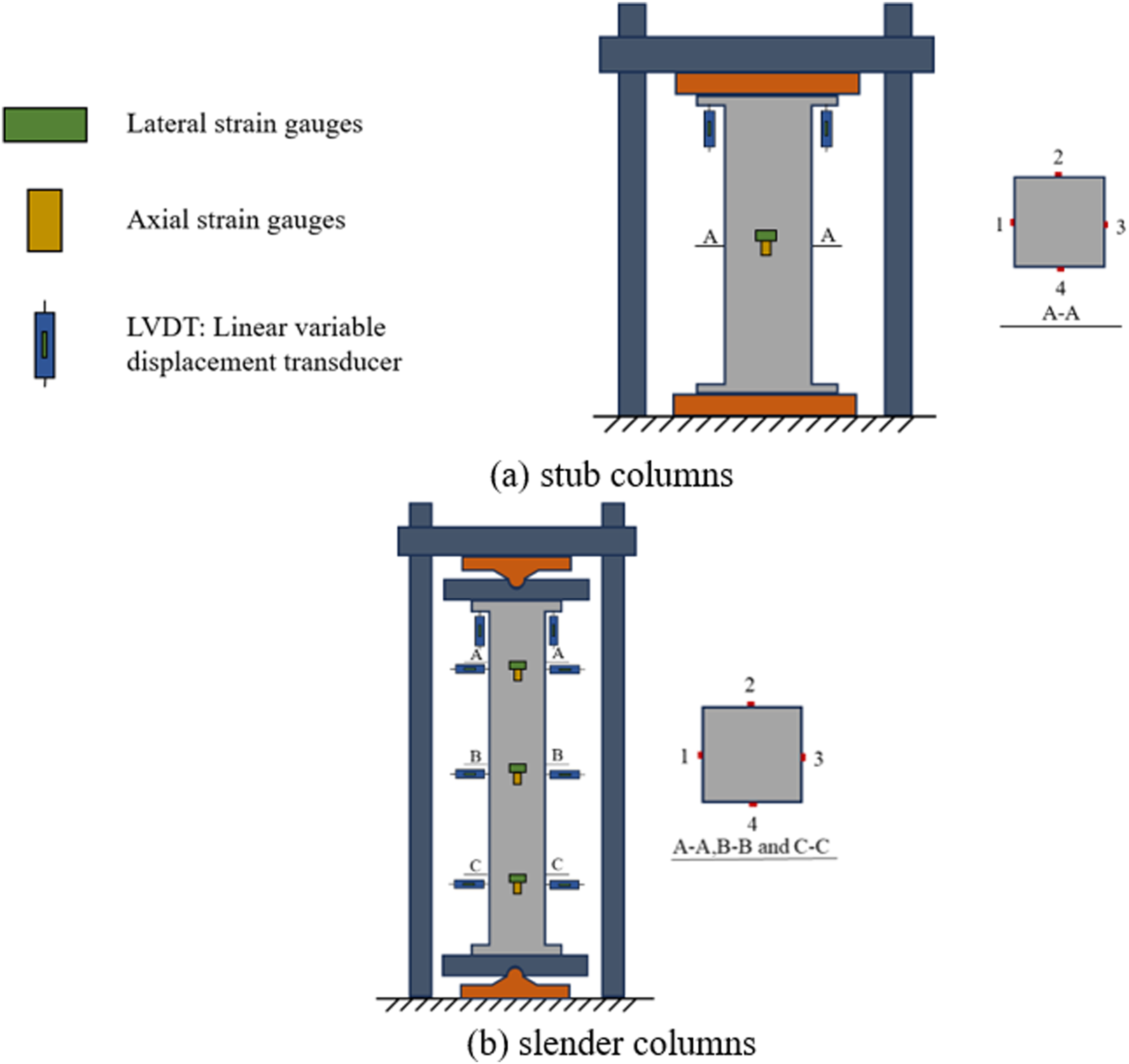
Longitudinal deformation was measured using two displacement transducers symmetrically placed along the specimen’s length. The applied load was monitored through the servo press’s integrated force sensing system. For stub columns, eight strain gauges were positioned at mid-height, spaced 90° apart longitudinally and transversely, to capture strain in the steel tube. For slender columns, 16 strain gauges were installed at one-quarter and three-quarters of the height, with similar spacing. At mid-height, three sets of longitudinal and lateral strain gauges were fixed on two adjacent sides, and one set was attached to each of the other two sides. Additionally, displacement transducers were placed at one-quarter, one-half, and three-quarters of the column height to measure lateral deflection. This arrangement facilitated comprehensive monitoring of strain distribution and deformation under axial loading.
Experimental results and discussions
Failure mode
Figure 3 illustrates the failure mode of stub columns. Severe outward bulging appeared locally along the column height when the load dropped to 80% of the ultimate value. This deformation spread to adjacent areas, ultimately resulting in a typical shear failure. And the shear failure modes for the lower concrete strength specimens are more obviously. Failure mode of stub columns.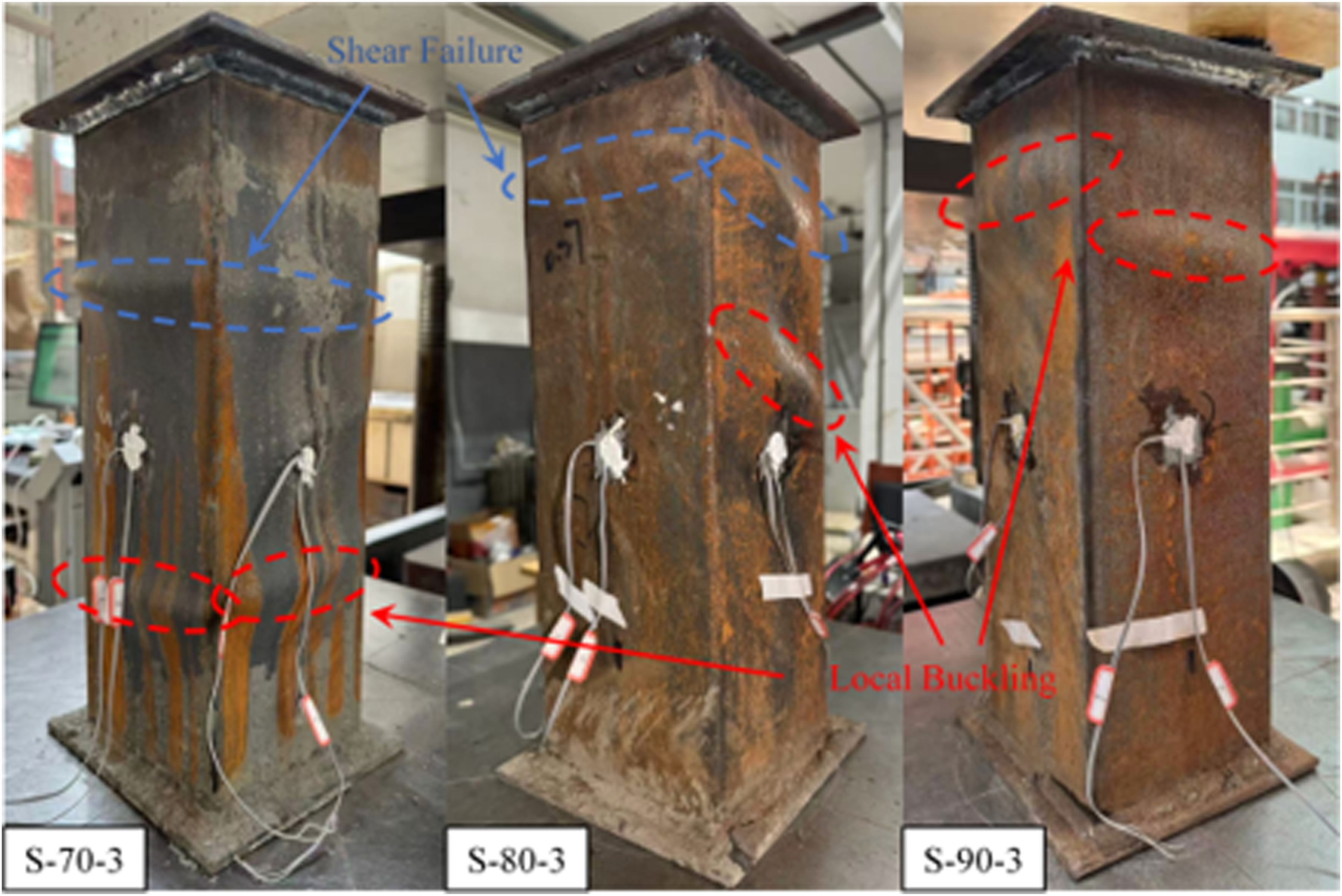
The failure mode of the slender columns is shown in Figure 4. The specimens exhibited substantial plastic deformation, with the steel tube on the compressed side of the mid-span section yielding. For specimens S-90-7, lateral deflection was minimal throughout loading until failure. Ultimately, the specimens experienced a strength failure mode, resembling the axial compression failure observed in stub columns. Local buckling of the steel tube occurred at the upper and lower ends after the peak load, indicating its minimal impact on the overall stable bearing capacity. Failure mode of slender columns.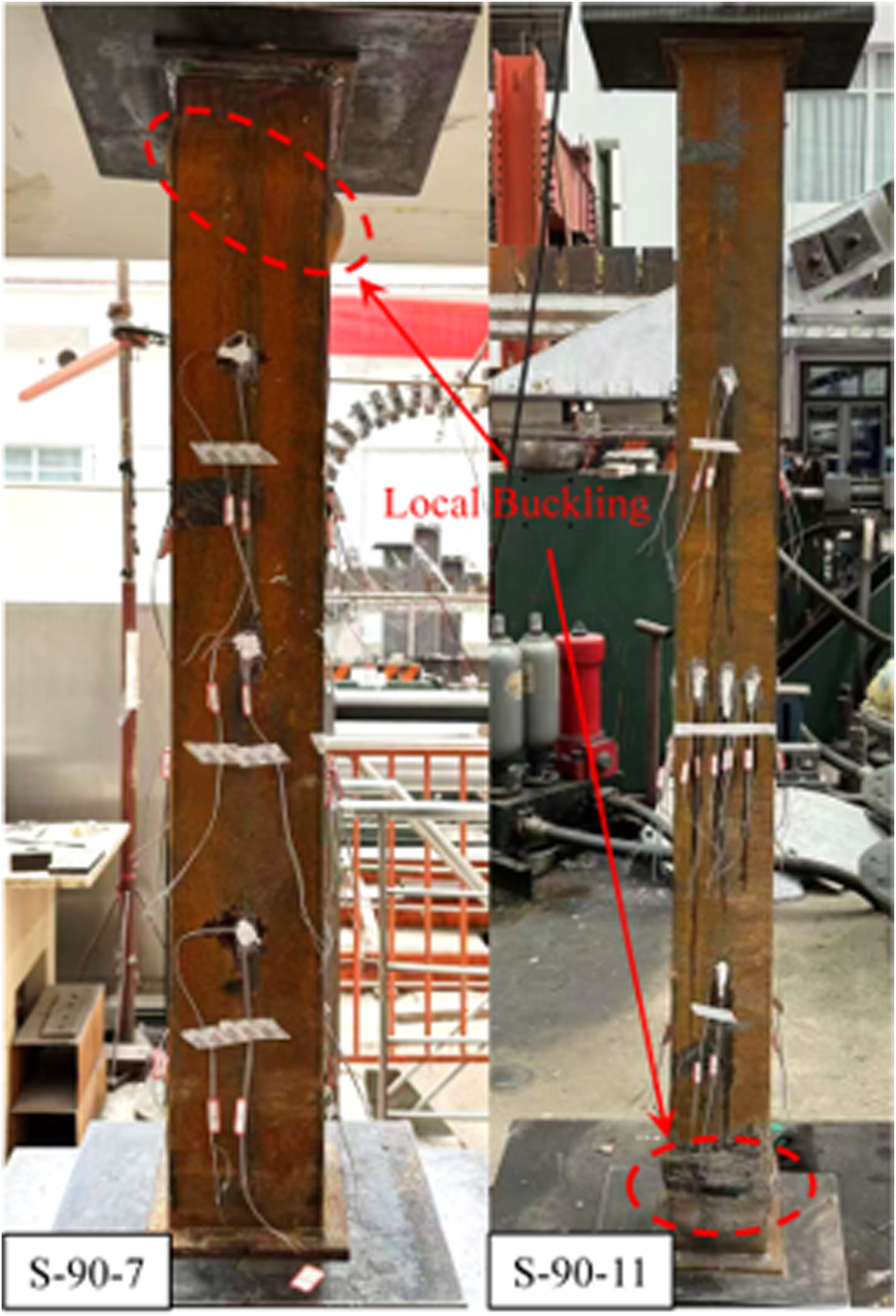
Load-deformation curves
The load-axial deformation curves for specimens with different HSFRAC strengths are shown in Figure 5(a). In the initial loading phase, the curves increase linearly, indicating consistent axial stiffness. Upon entering the elastoplastic stage, the curves diverge significantly. Due to the brittleness of HSFRAC, the axial displacement is small after the peak load, and the load drops abruptly, resulting in a steep downward curve. This behavior reflects a rapid loss of load-bearing capacity after failure, with no significant ductility observed. The discrepancy in axial load capacity observed between specimens within the same group is mainly attributed to the inherent material defects of fully recycled aggregate concrete and the relatively low ductility of high-strength concrete, which is prone to cause variability in local stiffness and cracking development. Load-axial deformation curves.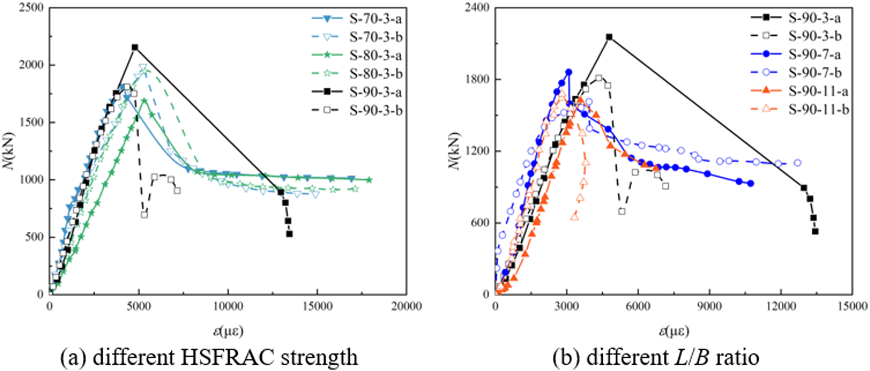
The load-axial displacement curves of square HSFRACFT columns with different L/B ratios are shown in Figure 5(b). The analysis indicates that the L/B ratio significantly affects the axial behavior of the specimens. As the L/B ratio increases from 7.4 to 11.8, the peak load gradually decreases, suggesting that a larger L/B ratio weakens the load-bearing capacity of the columns. In terms of deformation characteristics, specimens with an aspect ratio of 7.4 exhibit better ductility. After reaching the peak load, the S-90-7 series specimens demonstrate a gradual reduction in load-bearing capacity and stable residual strength, highlighting the effective confinement of the steel tube in suppressing crack propagation in the core HSFRAC. Experimental findings suggest an optimal L/B ratio threshold below 7 for achieving a balance of high load-bearing capacity and favorable ductility.
The load-lateral displacement curves for slender columns made of square HSFRACFT are shown in Figure 6. During the initial elastic stage, the load and lateral displacement (labeled as Um) increase linearly, indicating high stiffness and small deformation. As the load increases, the interaction between the steel tube and the core HSFRAC strengthens, transitioning the specimens into the elastoplastic stage. Deformation accelerates, and the curve becomes nonlinear. With further loading, local buckling appears, accompanied by sounds of HSFRAC crushing. At the peak load, the curve exhibits a distinct inflection point. Beyond the peak, the load decreases sharply, and deformation increases rapidly. When the load drops to about 80% of its peak, deformation intensifies further, and localized failure propagates. Ultimately, the specimens reach complete failure, with the curve leveling off. In addition, the specimen with a smaller slenderness was found to exhibit a steeper ascending branch (i.e., larger stiffness), which is same with the observation in previous study (Lin et al., 2022), suggesting the tested results is reasonable. It should be noted that the lateral displacement shown in Figure 6 corresponds to the mid-height displacement of slender columns, which is highly sensitive to member imperfection and thus caused slight fluctuation in stiffness. Overall, the curves reflect high initial stiffness, a progressive load increase, and a sharp decline in bearing capacity after the peak load, highlighting the brittle failure behavior of the structure. Load-lateral deflection curves.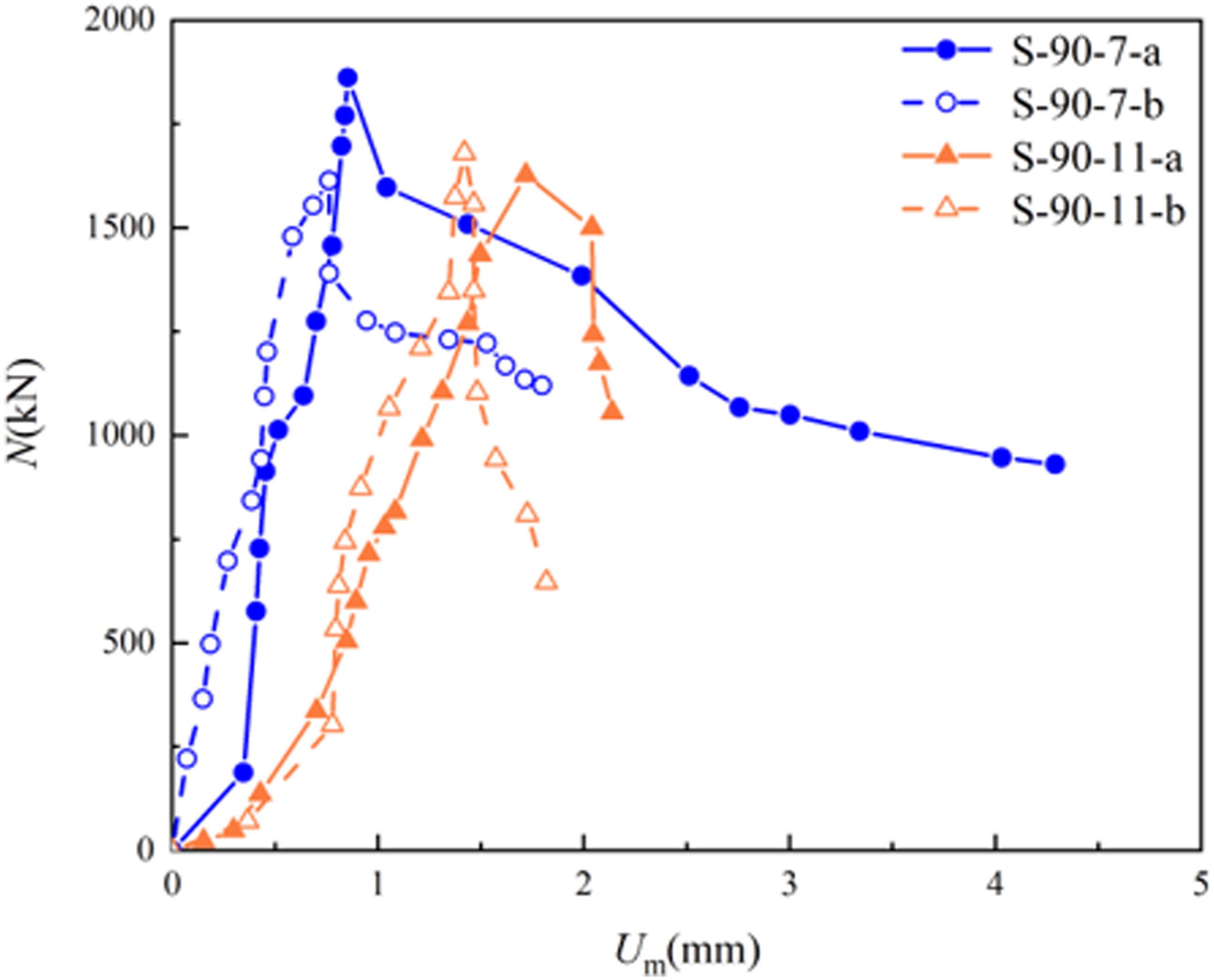
The lateral deflection curves at different load stages from the beginning of loading to the peak load are shown in Figure 7. Due to initial geometric and physical imperfections, as well as load eccentricity, the critical section of the specimens does not always align with the midspan, resulting in the maximum lateral deflection occurring at positions other than the midpoint. The axial load-lateral deflection curves exhibit different patterns. For the specimens with an L/B ratio of 7.4 and 11.8, deformation is more significant at the top and bottom, while lateral deflection is smaller. This behavior resembles the failure mode of stub columns and is more indicative of strength failure. Development of lateral deflection.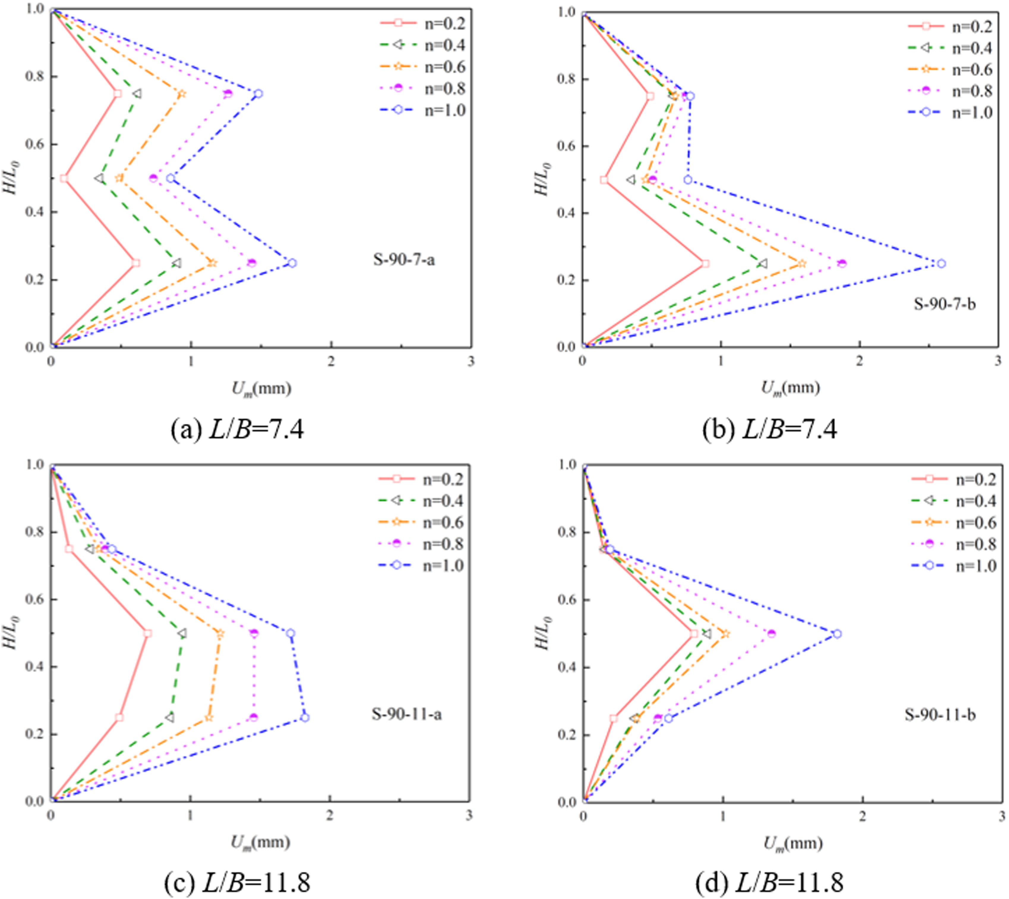
Load-bearing capacity
Table 1 presents the measured bearing capacities of all square HSFRACFT columns, where Nexp represents the experimentally determined bearing capacity of the specimens. Figure 8(a) highlights the relationship between HSFRAC strength and the bearing capacity of square HSFRACFT columns, suggesting that higher HSFRAC strength enhanced the bearing capacity of the specimens. Load-bearing capacities of specimens.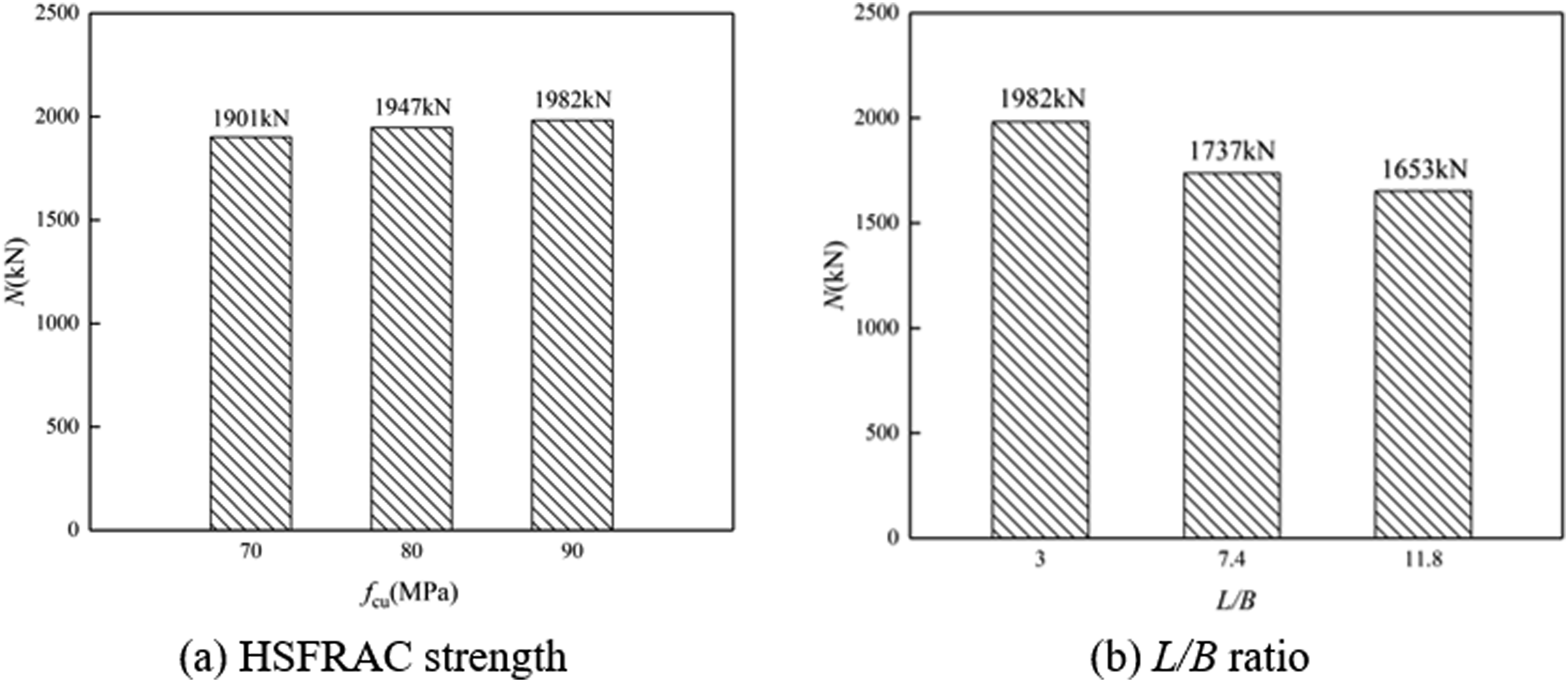
Figure 8(b) illustrates the effect of L/B ratio on the bearing capacity of these columns, showing a clear reduction in bearing capacity as the L/B ratio increases. Higher L/B ratios reduce the stability of the columns, leading to lower bearing capacity, columns with smaller L/B ratios exhibit greater bearing capacity.
Ductility performance and combined effect
The deformation capacity of square HSFRACFT columns is evaluated by ductility factor DI, defined as follow: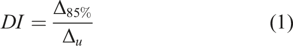
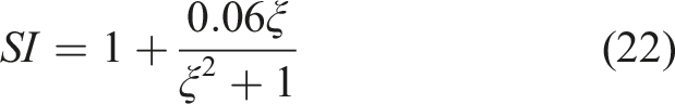
The composite effect of square HSFRACFT columns is evaluated by the strength factor SI, which was same with that of (Zhong, 2023) and is defined as follows: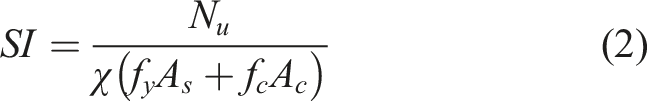


In addition, the confinement factor ξ is defined as equation (8), and is also aimed to evaluate the restraining effect of the external steel tube on the core concrete.
The results of ductility factor DI and strength factor SI are shown in Table 1. The ductility factor DI of square HSFRACFT columns is less than 1.3, indicating that the load-bearing capacity of the specimen declined rapidly after the peak load, and the ductility is relatively limited. The strength factor SI increase with the confinement factor ξ and in particularly, the confinement factor ξ of specimens with compressive strength of 70 MPa are more than 1.1, reflecting the composite effect between steel tube and concrete are relatively better. The specimens with larger length-to-width ratios might exhibit weaker ductility due to the higher possibility of instability under a smaller displacement.
Compared with normal-strength fully recycled aggregate concrete-filled steel tubular (NSFRACFT) columns, the HSFRACFT columns investigated in this study exhibit higher initial stiffness and axial load capacity, indicating their advantage in strength-oriented structural design. However, HSFRACFT columns experienced reduced lateral deformation capacity and more pronounced post-peak softening behavior compared with NSFRACFT columns, which may lead to reduced energy dissipation potential and limit its application in deformation-demanding scenarios.
Numerical analysis
The load-bearing capacity trends observed from the limited experimental data in this study have certain limitations. Numerical analysis using finite element simulations, is conducted in this section to fully understand the axial behavior of square HSFRACFT columns.
Details of the finite element model
To comprehensively assess the influence of structural parameters on the mechanical performance of square HSFRACFT columns, a finite element model (FEM) was developed in ABAQUS for parametric analysis. The FEM comprised a steel tube, core concrete and two end plates, all modeled using three-dimensional 8-node solid elements (C3D8R). The end plates were modeled as rigid bodies, characterized by a small Poisson’s ratio and a high elastic modulus. Since mesh size affects the computational accuracy and efficiency of the FEM, several trial simulations with different mesh densities were conducted. The results showed that further mesh refinement beyond the adopted mesh had a marginal effect on the predicted load-bearing capacity and overall response. Accordingly, a final element size of 25 mm was selected. Surface-to-surface contact was applied to simulate the interaction between the HSFRAC and the steel tube. In the normal direction, “hard contact” was defined to ensure effective pressure transmission between the steel tube and the HSFRAC without separation. Tangential contact was modeled using the “Coulomb friction model” to capture interfacial sliding and frictional restraint behavior. The end plate was defined as being in “hard contact” with the HSFRAC to ensure load transfer, and was rigidly connected to the steel tube via “tie contact” to eliminate interface separation. The loading scheme of the end plate replicated the experimental setup, and the FEM configuration is shown in Figure 9. FEM of square HSFRACFT columns.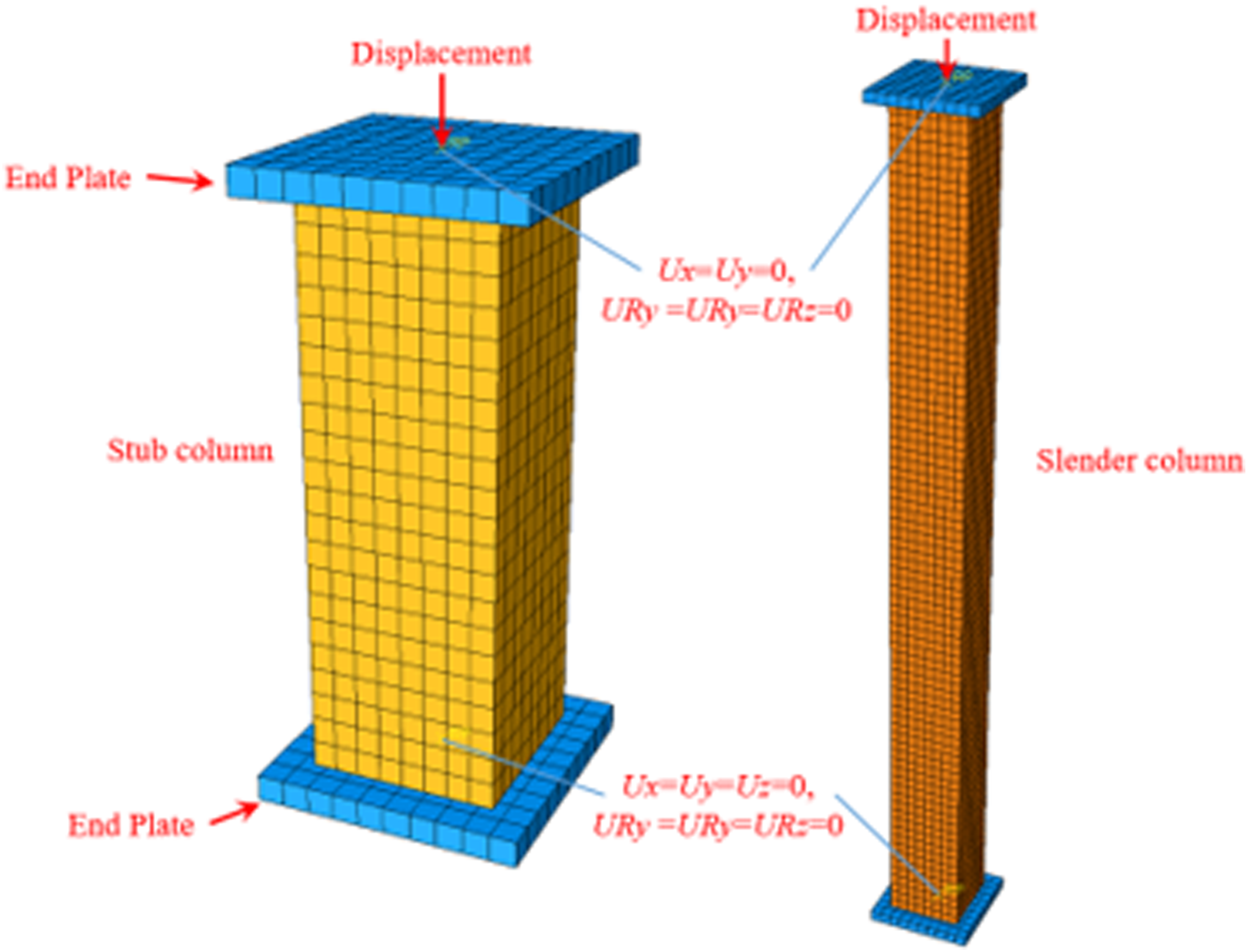
Constitutive relationships
Steel tube. The square HSFRACFT columns in this test used Q235 steel with a yield strength
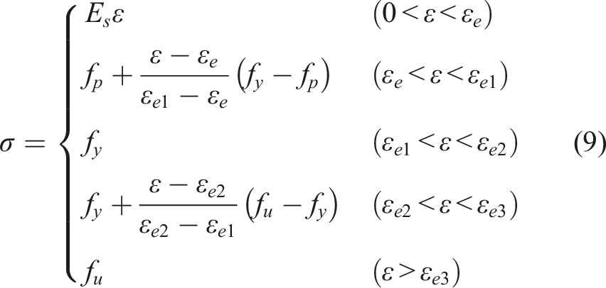
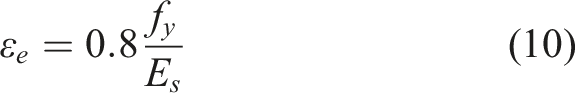


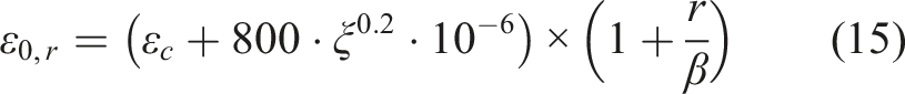
Core HSFRAC. In this study, the stress-strain model for RAC in HSFRACFT was established by adopting the stress-strain expression for confined concrete in CFST proposed by Han et al. (2007), in conjunction with the modification method for RAC mechanical properties suggested by Lyu et al. (2021). The resulting stress-strain relationship was used to model the compressive behavior of HSFRAC, and the detailed equations are illustrated in equations (14) to (19).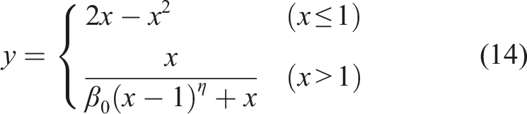


The fracture energy (GF) model (Bažant and Becq-Giraudon, 2002) was adopted to define the tensile behavior of HSFRAC:
The mechanical behavior of concrete was simulated using a concrete damaged plasticity (CDP) model (Lin et al., 2026). The key parameters of the model include the dilation angle (ψ), flow potential eccentricity (e), the ratio of biaxial to uniaxial compressive strength (fb0/fc’), the ratio of the second stress invariant on the tensile to compressive meridian (Kc), and the concrete viscosity coefficient (μ). These parameters were determined as ψ = 30°, e = 0.1, fb0/fc’ = 0.67, Kc = 1.16 and μ = 0.0001.
Verification of the FEM
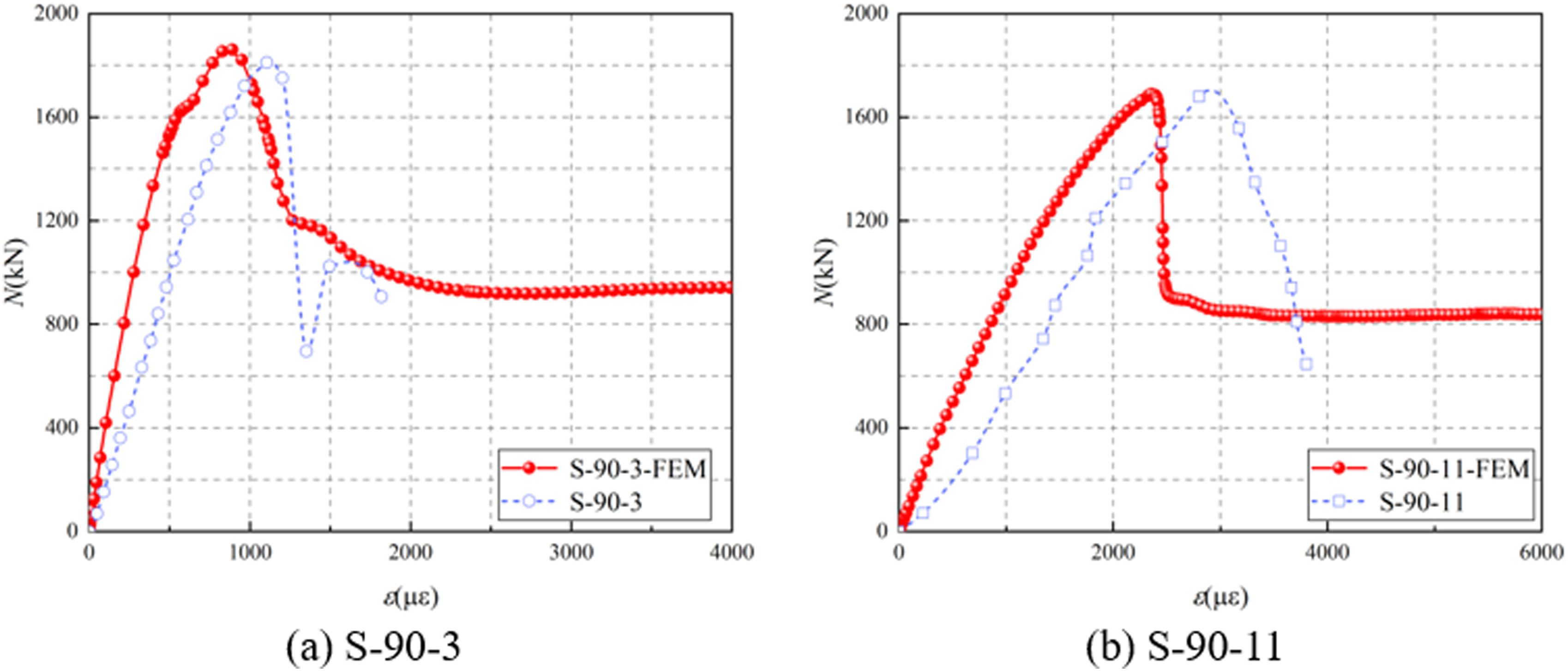
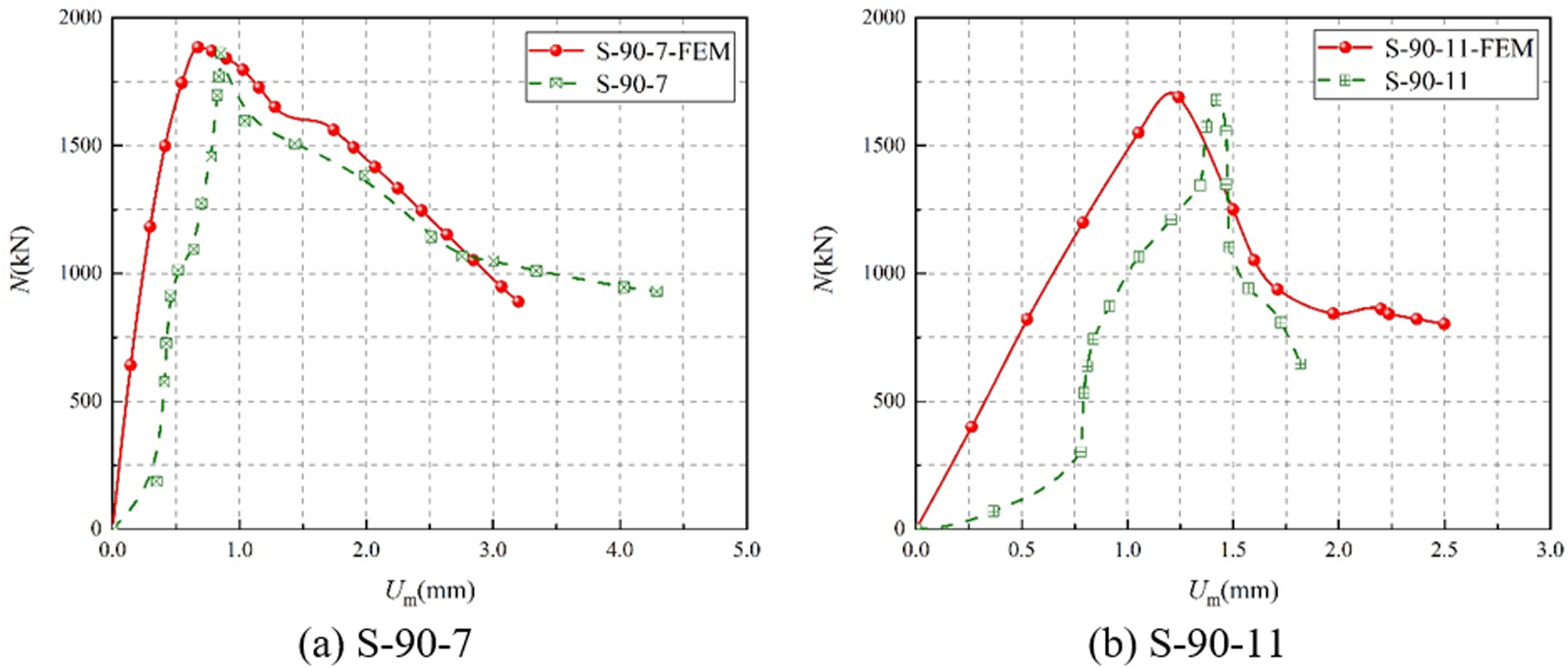
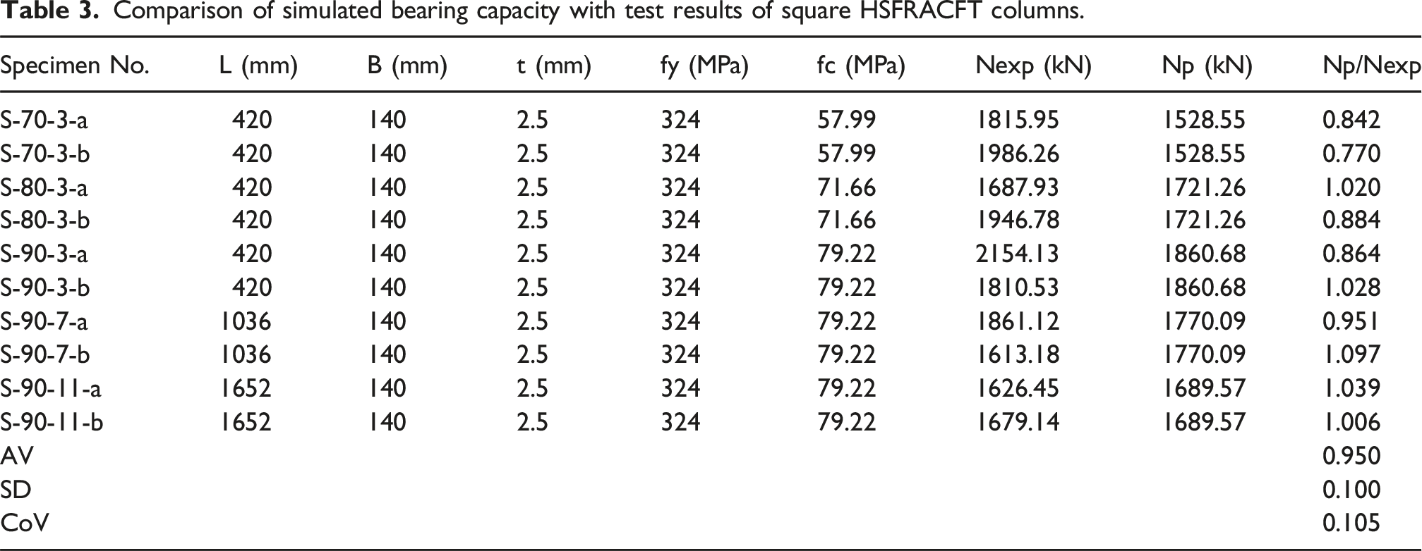
The failure modes observed in the simulations, corresponding to the experimental results, are shown in Figure 10. For each specimen, the numerical model successfully captures the dominant failure characteristics observed in the tests, including local buckling of the steel tube at the mid-height of stub columns and the ends of slender columns, and the overall deformation pattern. Figures 11 and 12 present comparisons between experimental and simulated load-axial strain curves and the load-lateral deflection curves, respectively. The load-bearing capacity (N
exp
for the test and N
p
for simulation) are illustrated in Table 3. The average value (AV) of Np/Nexp is 0.95, the standard deviation (SD) of Np/Nexp is 0.1 and the coefficient of variation (CoV) of Np/Nexp is 0.105. Results suggested that the numerical results are in good agreement with the experimental data of square HSFRACFT columns. Failure modes of FEM for square HSFRACFT columns (a) stub columns; (b) slender columns. Load-axial strain curves of FEM for square HSFRACFT columns. Load-lateral deflection curves of FEM for square HSFRACFT columns. Comparison of simulated bearing capacity with test results of square HSFRACFT columns.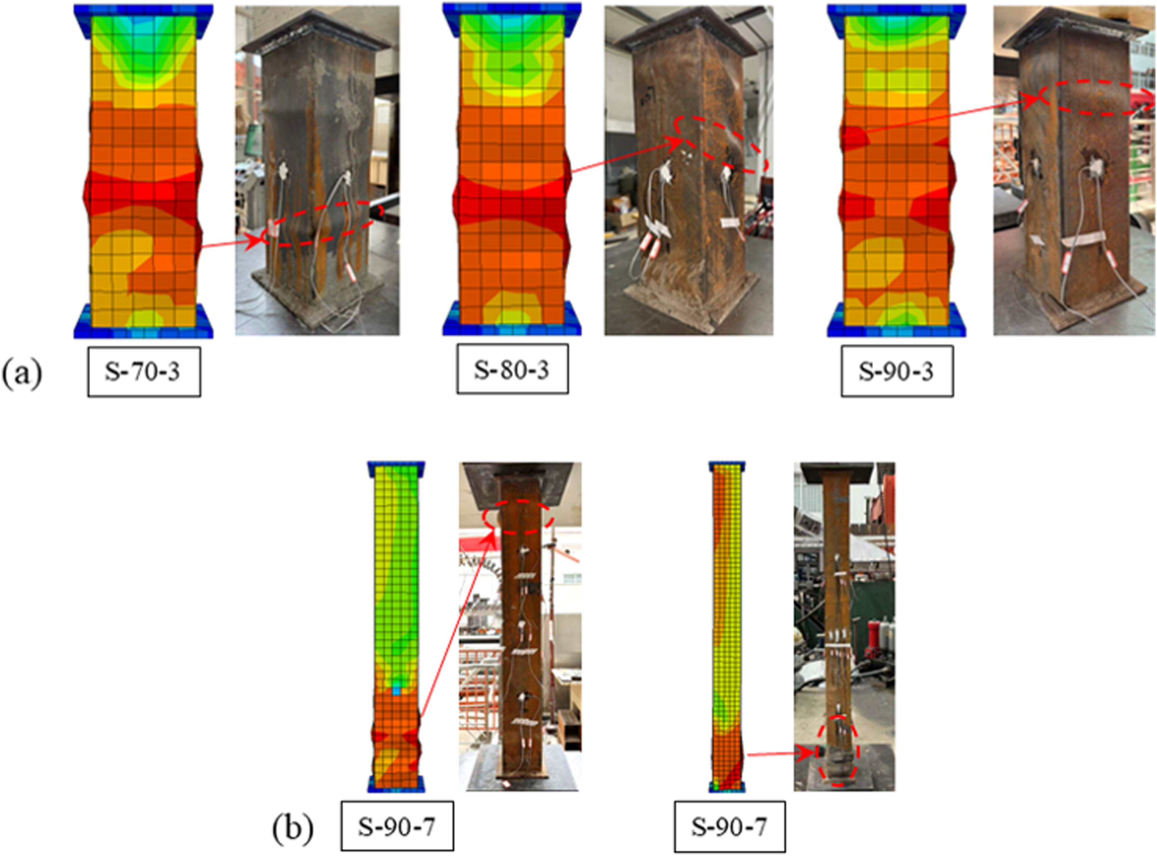
Some discrepancies between the finite element predictions and experimental results can be observed. These differences may be attributed to several factors. First, the material constitutive models adopted for recycled concrete and steel tube are idealized and may not fully capture the inherent heterogeneity and localized damage of recycled aggregate concrete. Second, simplified boundary conditions and perfect bond assumptions were employed in the numerical model, whereas slight eccentricities and interface imperfections may exist in the experiments. Third, mesh discretization may influence the prediction of local buckling and damage localization. Nevertheless, the finite element model accurately captures the overall load-bearing capacity and failure characteristics, which are the primary focus of this study.
Parameter analysis
To investigate the mechanical behavior of square HSFRACFT columns, a parametric analysis was conducted using the validated FEM to assess the influence of concrete strength, the steel yield strength, width-to-thickness ratio and length-to-width ratio on load-axial deformation curve, load-bearing capacity and ductility. The parametric cases include three levels of concrete strength (50, 80, and 110 MPa), three levels of steel yield strength of (300, 500, and 700 MPa), three width-to-thickness ratios (20, 60, and 100), and three length-to-width ratios (12, 36, and 60).
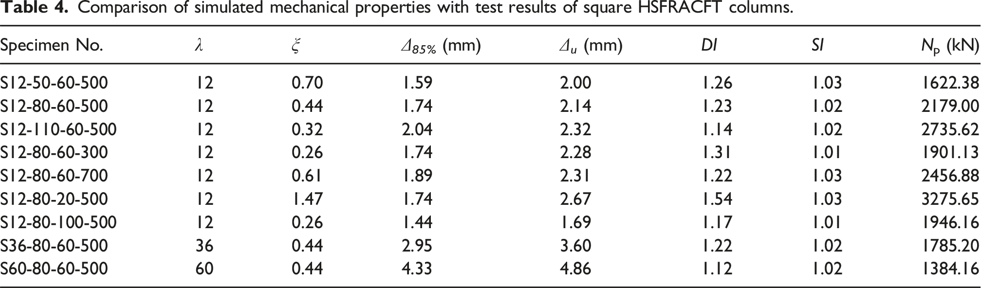
The numerical results corresponding to different parameters are presented in Figure 13 and Table 4. The specimen naming convention is as follows: the letter “S” indicates a square cross-sectional, followed by four numbers indicating the length-to-width ratio, concrete strength, width-to-thickness ratio, and steel yield strength, respectively. As the core concrete strength increases from 50 MPa to 110 MPa, the load-bearing capacity increases by approximately 73% while the ductility factor decreases by about 10%. With increasing concrete strength, brittleness becomes more pronounced, accelerating crack development and reducing the ductility of square HSFRACFT columns. A larger steel yield strength and a lower width-to-thickness ratio enhance the confinement effect of the steel tube, thereby improving the ductility factor. Additionally, the length-to-width ratio affects the load-bearing capacity of the columns but has minimal influence on their ductility. Impact of parameters on load-axial deformation curves. Comparison of simulated mechanical properties with test results of square HSFRACFT columns.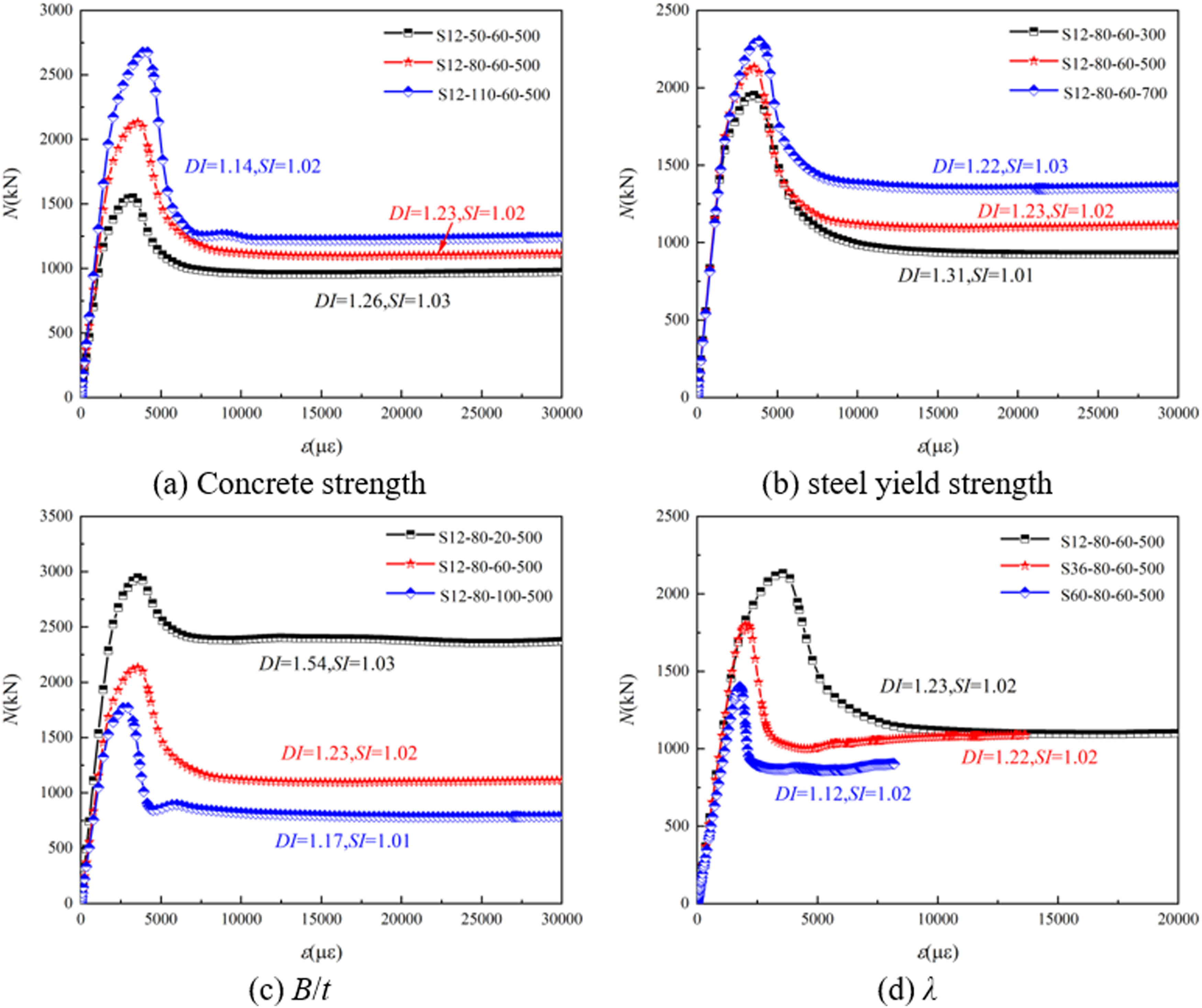
The influence of the confinement factor ξ on the ductility factor (DI) and strength factor (SI) is illustrated in Figure 14. Based on the FEM parametric analysis, the ductility factor DI and strength factor SI can be expressed as functions of the confinement factor ξ as follows: Relationship between ξ and DI, and between ξ and SI.
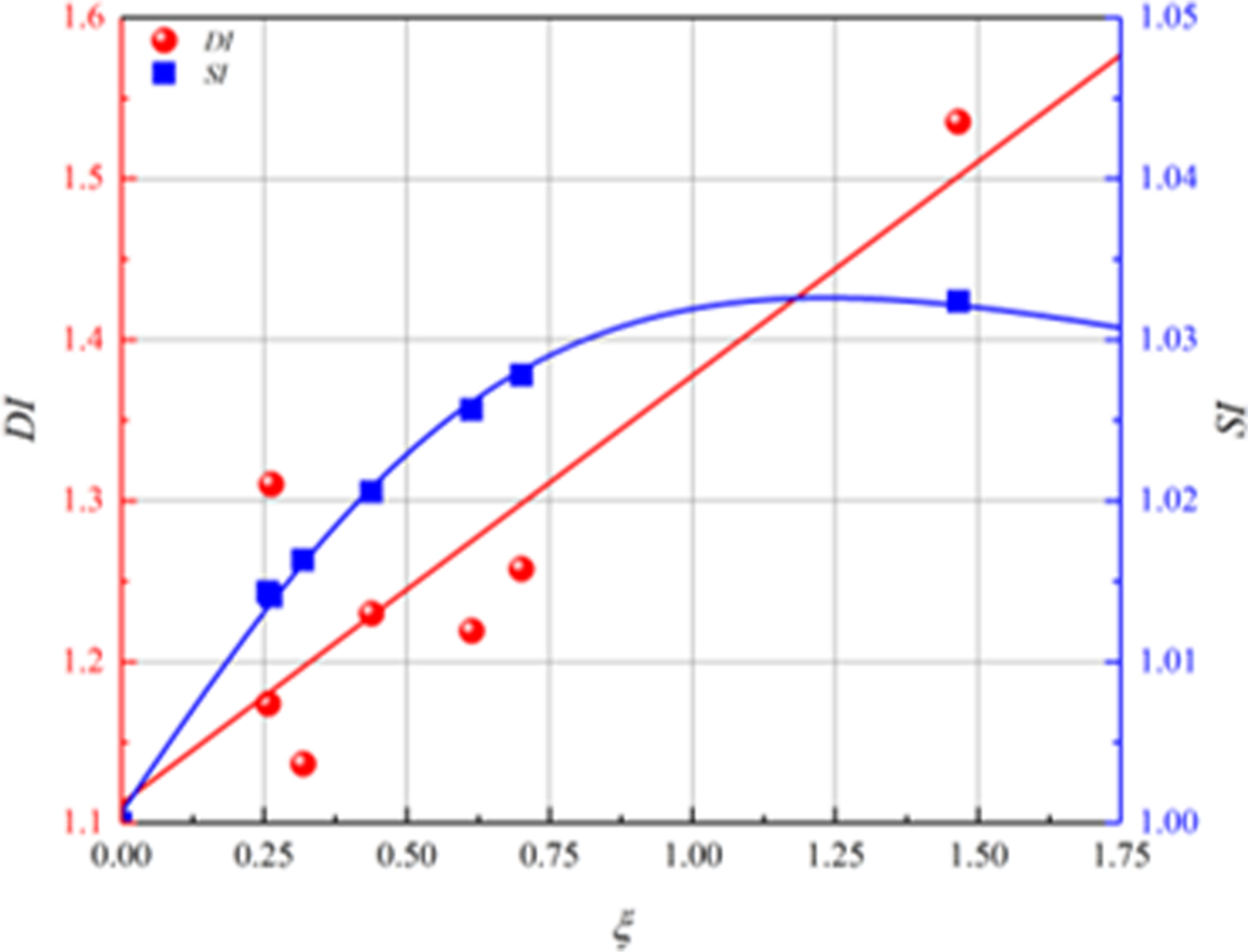
As shown in the above equation, increasing the confinement factor ξ effectively enhances the ductility of columns. Specifically, when the confinement factor ξ exceeds 1.45, the ductility factor DI surpasses 1.5, indicating that the column exhibits favorable ductility. However, the strength factor SI were quite small (<1.05) even for a large confinement factor ξ (e.g., ξ = 1.5), suggesting limited composite effects of square HSFRACFT columns. Therefore, to fully exploit the ductility and composite effects of square HSFRACFT columns, it is recommended to moderately increase the confinement factor and incorporate additional confinement measures, such as internal spiral stirrups or tie rods.
Design of axial load bearing capacity
Concrete-filled steel tube (CFST) structures are widely utilized, and extensive research on CFST columns has been conducted both domestically and internationally. As a result, comprehensive design systems have been established, including EC4 (2004), AISC-360-22 (2022), and GB50936 (2014). However, these design codes are primarily tailored for conventional concrete and impose limitations on steel yield strength, concrete compressive strength, and the specimen’s L/B ratio. To facilitate the engineering application of HSFRACFT structures, it is essential to develop new models for the load-bearing capacity of square HSFRACFT columns.
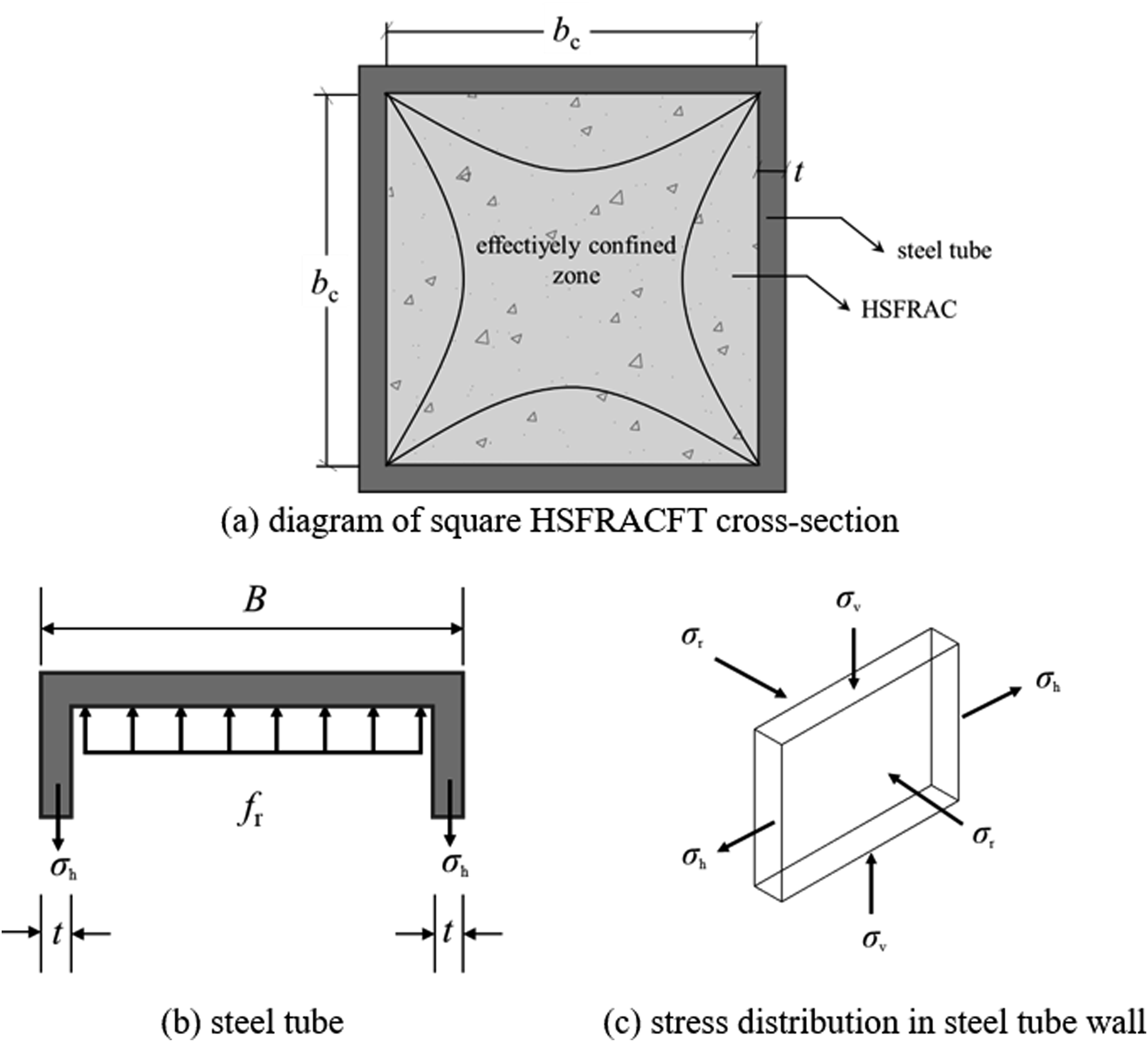
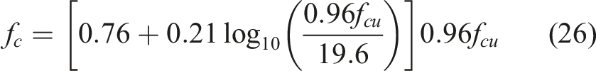
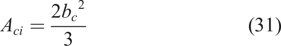
The load-bearing capacity of square HSFRACFT columns primarily depends on mechanical properties of the external steel tube and the HSFRAC. Based on theoretical analysis of the force conditions and existing experimental data, this study proposes a new design formula for load-bearing capacity. The confinement effect exerted by the square steel tube on the core HSFRAC exhibits non-uniform distribution. Therefore, the constrained area of the square HSFRACFT columns can be divided into effective constraint zones and non-effective constraint zones. The boundary between these zones can be approximated by a parabolic curve, with the corner angle of the effective constraint zone being approximately 45°(Liang et al., 2021a; 2021b).In this study, the constraint effect of the non-effective constraint zone on the HSFRAC is neglected. Accordingly, the load-bearing capacity of the square HSFRACFT column is given as:
The force condition of the cross-section of a square HSFRACFT column is shown in Figure 15, where σv represents the vertical stress of the steel tube, σ
h
represents the hoop stress, σ
r
represents the radial stress. When Force diagram of square HSFRACFT.
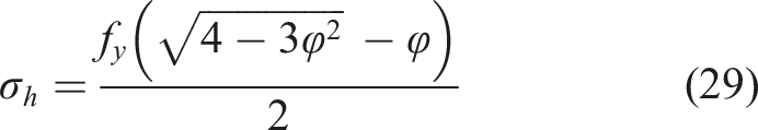
Assume the steel tube is an ideal elastic-plastic material, it follows the Von Mises yield criterion, which can be expressed as:
The core HSFRAC in square HSFRACFT column is classified as passively confined HSFRAC. This study adopts the passive confinement model proposed by Li et al. (Li et al., 2022), as shown below:
According to equilibrium conditions, the average lateral pressure acting on the core HSFRAC is calculated.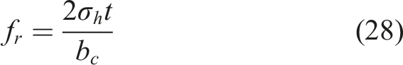
The cross-sectional areas of the effectively and non-effectively constrained zones of square HSFRACFT are calculated based on methods from Lin et al., (2020).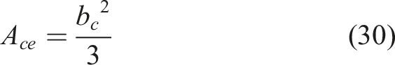
Details of the collected concentrically loaded square RACSFT columns.
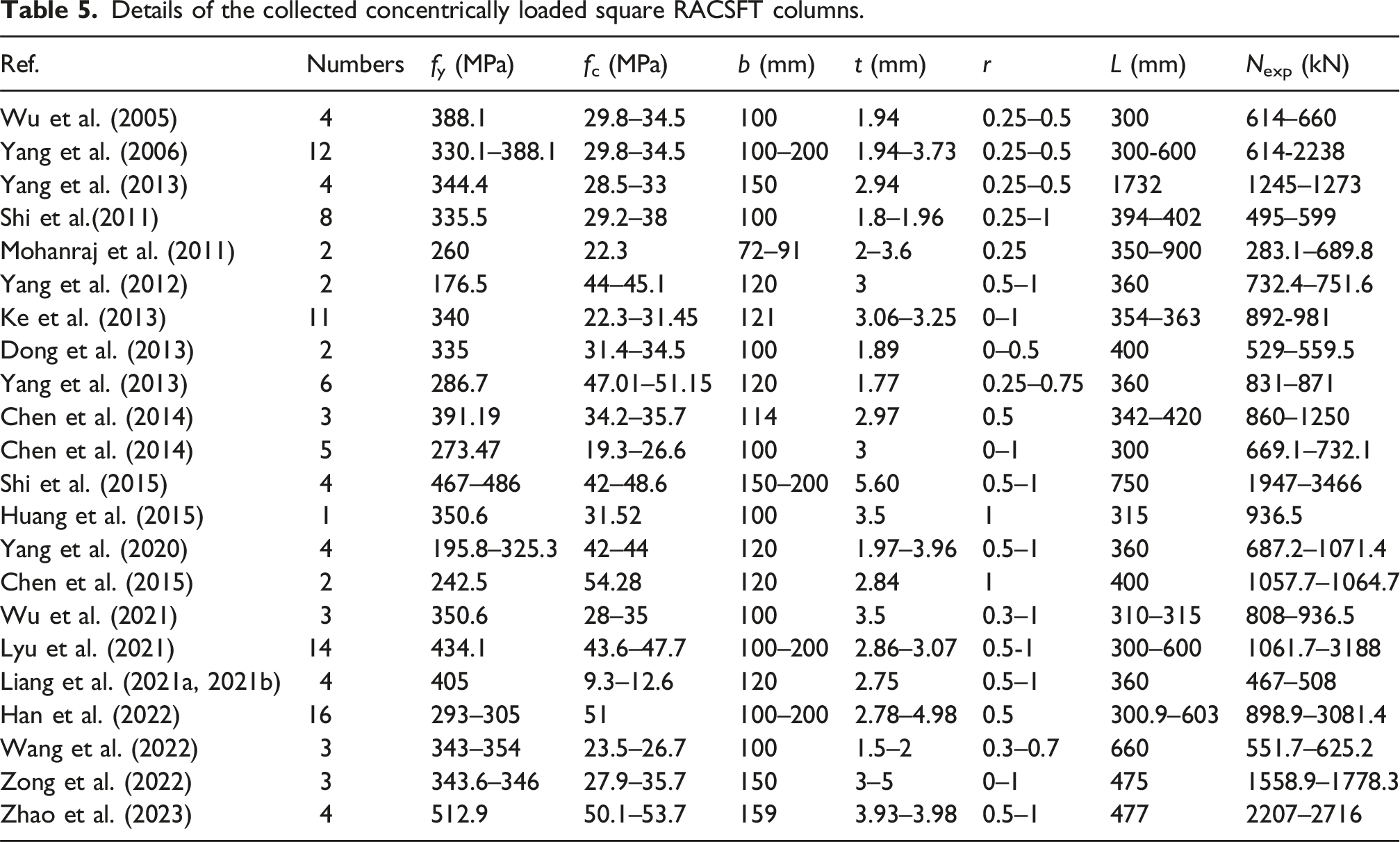
To further validate the accuracy and applicability of the formula, this section presents statistical results from 117 square RACFT columns. A comparison between the calculation results and the experimental results from this study is shown in Figure 16(a), while a comparison with all statistical experimental results is shown in Figure 16(b). In the figures, Npro represents the load-bearing capacity calculated by the model, and Nexp represents the experimentally measured load-bearing capacity. Comparison of bearing capacity between calculated and test results.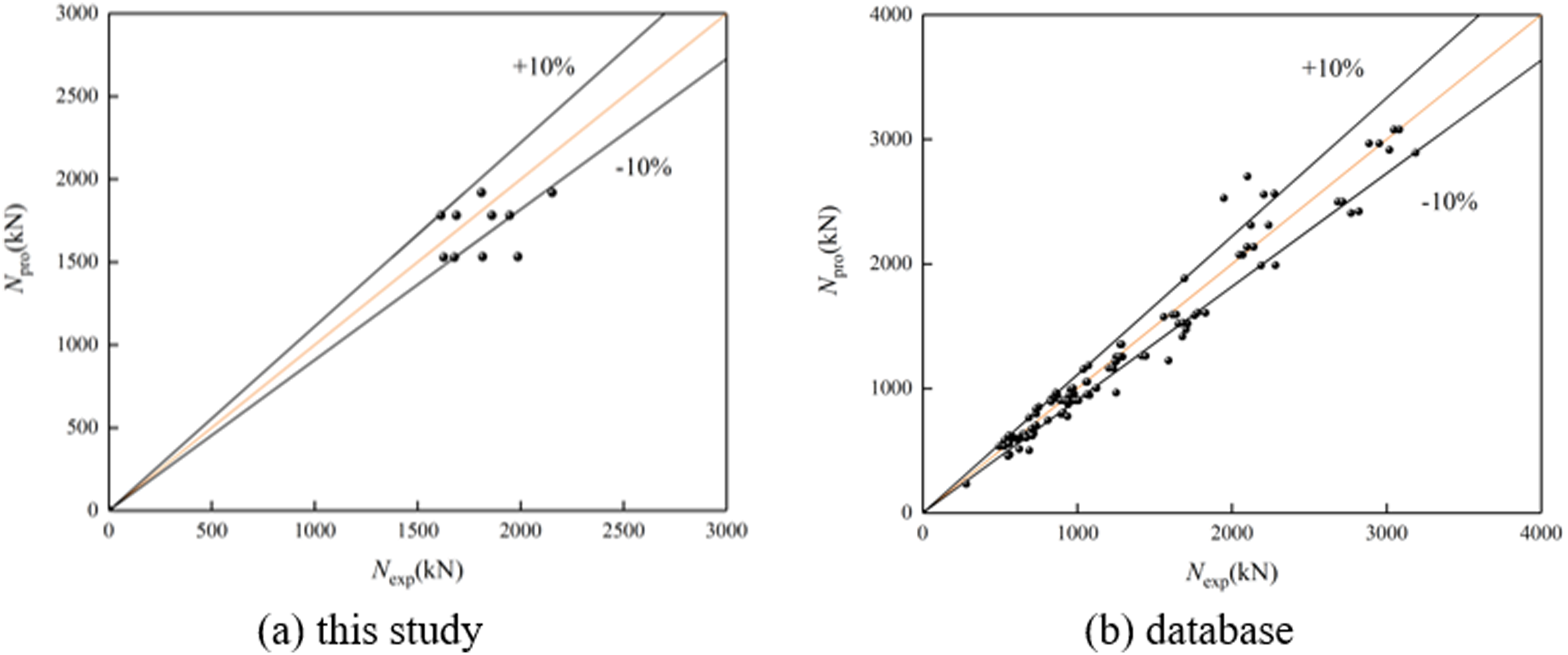
In this experiment, the mean value of Npro/Nexp is 0.945, with a coefficient of variation (COV) is 0.104. For all the statistical experimental data, the mean value of Npro/Nexp is 0.984, with a COV is 0.107. These results demonstrate that the model effectively predicts the axial compressive load-bearing capacity of square RACFT columns.
Conclusions
This study experimentally investigated the influence of HSFRAC strength and length-to-width (L/B) ratio on the axial compressive behavior of square HSFRACFT columns. The main conclusions are summarized as follows: (1) Stub columns exhibited local buckling at both the ends and middle-height, often accompanied by diagonal shear failure. In contrast, slender columns showed pronounced buckling at the ends, but exhibited limited lateral deformation at failure. The L/B ratio had a more significant influence on the axial compressive behavior than the compressive strength of HSFRAC. With increasing L/B ratio, both the load-bearing capacity and stiffness decreased, resulting in reduced overall stability. (2) Experimental results indicated that the square HSFRACFT columns exhibit poor ductility and composite effect when the confinement factor 0.31≤ ξ ≤ 0.42. Numerical analysis showed that increasing the confinement factor enhances the ductility but hardly improves overall composite strength. Therefore, it is recommended to moderately increase the confinement factor and incorporate additional confinement measures, such as internal spiral stirrups or tie rods, if using square HSFRACFT columns in practical engineering. (3) An axial load-bearing capacity model of square HSFRACFT columns is proposed. Comparison with 117 experimental datasets demonstrates that the proposed model offers high accuracy and applicability for predicting the load-bearing capacity of both stub and slender columns.
Footnotes
Acknowledgments
Recognition and gratitude are expressed for the service provided.
Funding
The authors disclosed receipt of the following financial support for the research, authorship, and/or publication of this article: This research is partially supported by funding from the Beijing Nova Program (Grant No. 20230484353), National Natural Science Foundation of China (Grant No. 52178099) and Research and Application of Industrial Technologies for Functional Improvement of Existing Communities (Grant Nos. CSCEC-2024-Z-27).
Declaration of conflicting interests
The authors declared no potential conflicts of interest with respect to the research, authorship, and/or publication of this article.
Data Availability Statement
The information produced throughout the research can be obtained from the authors upon a reasonable request.