



Abstract
A constitutive model of confined ultra-high-performance concrete (UHPC) was developed based on the theoretical and regression analyses. This constitutive model could be applied to finite element analysis (FEA) according to the comparison of plastic damage analysis and load–displacement curves. A total of 25 stirrup-confined UHPC columns were created through FEA modeling. The variables included stirrup spacing, stirrup configuration, steel fiber volume, and longitudinal reinforcement ratio. The load–displacement curves and the plastic damage region of the UHPC columns were illustrated and analyzed. Moreover, parametric analysis was conducted to evaluate the effects of the aforementioned parameters. The improvement in the bearing capacity and ductility of the UHPC columns resulting from the reduction in stirrup spacing and increase in steel fiber volume indicated that the columns were significantly influenced by the stirrup spacing, stirrup configuration, and steel fiber volume.
Keywords
Introduction
In recent years, a number of research works have been conducted to formulate techniques for avoiding the brittle failure of high-strength concrete (HSC) columns for high-rise building applications (Cusson and Paultre, 1994; Chen et al., 2018). Existing studies show that the application of stirrups with different spacing and cross-section details can effectively improve the ductility of concrete columns (Sharma et al., 2015; Shin et al., 2016). In addition, the incorporation of steel fibers can provide additional confinement, which delays the spalling of concrete and improves the axial bearing capacity and ductility of concrete columns (Paultre et al., 2010; Shin and Yoon, 2015; Shin et al., 2017; Ahmed and Hadi Muhammad, 2018). Ultra-high-performance concrete (UHPC) is one of the emerging cement-based composite materials with exceptional mechanical properties, such as superior compressive and tensile strengths and remarkable toughness (Xu et al., 2017; Marchand et al., 2019). The UHPC also exhibits excellent ductility, fatigue performance, and durability compared with ordinary concrete and HSC. Accordingly, the UHPC is an attractive alternative option for high-rise building applications. Numbers of studies have been conducted to investigate the axial compressive performance of UHPC columns. Eight UHPC columns were tested by Empelmann et al. (2008) to investigate the axial compressive performance of UHPC columns; all the columns were 600 mm long and had the same cross-sectional dimensions (200 mm in width and 200 mm in depth). It was observed that the ductility of the columns was significantly improved by providing adequate stirrup and steel fibers. Hosinieh et al. (2015) tested six large-scale columns under pure axial loading, and the results showed that the spacing and type of stirrups can substantially affect the performance of the columns. Xu et al. (2018) conducted numerical simulations to study the behavior of UHPC columns subjected to axial compressive loading and horizontal monotonic push loading. The variables considered mainly included steel fiber volume, axial compression ratio, stirrup ratio, and shear span ratio. The results showed that the finite element analysis (FEA) model accurately predicted the behavior and failure mode of the UHPC columns. To study the influence of the spiral reinforcement volumetric ratio, concrete compressive strength, and presence of steel fibers on the performance of UHPC columns, Shin et al. (2018) fabricated six large-scale UHPC columns confined by spiral stirrups, in which the volumetric ratio of the hybrid micro-steel fibers used was 1.5% and the compressive strengths varied in the range of 163–181 MPa. It was reported that the improvement in the ductility of the UHPC column resulted from the combined action of steel fibers and spiral stirrups.
Existing research works mainly focused on UHPC column tests. However, relatively few works utilized the FEA. This article proposes a constitutive model of the confined UHPC based on the theoretical and regression analyses. Considering the variation in stirrup spacing, stirrup configuration, steel fiber volume, and longitudinal reinforcement ratio, a total of 25 stirrup-confined UHPC columns were created through FEA with the application of the developed constitutive model, which subjected to an increasing axial compressive load. The axial compressive behavior, load–displacement curves, and plastic damage region of the columns were investigated.
Constitutive models of ultra-high-performance concrete
Typical constitutive models
Typical constitutive models.

Note:
Confining pressure analysis
Confining pressure provided by stirrups
The confined UHPC has a three-direction compressive stress because of the confinement provided by the stirrups. Horizontal bending would occur on the stirrups because of the lateral deformation of the confined concrete under the axial load. It is assumed that the pressure provided by the stirrups is evenly distributed along the stirrup side length. Accordingly, the lateral confining pressure can be obtained based on the principle of the equilibrium equation, as expressed in equation (1)
Mander et al. (1988) modified the area of the effective confined concrete and proposed an expression for the effective confining pressure provided by stirrups, as expressed in equation (2)
The comprehensive influence of stirrup configuration, longitudinal reinforcement distribution, and sectional dimension are given in equations (3a)–(3c)


Confining pressure provided by steel fibers
The additional confinement provided by steel fiber has a significant effect on the peak stress and peak strain (Hosinieh et al., 2015). Aoude (2008) proposed a fiber-reinforced concrete confinement model. This model modifies the expressions proposed by Cusson and Paultre (1995) and Légeron and Paultre (2003) to incorporate the confining pressure provided by steel fibers, where this confining pressure is obtained by multiplying the number of steel fibers and their average pull-out strength, as follows
Peak stress and peak strain
To consider the influence of steel fibers on the peak stress and strain, a comprehensive confining coefficient


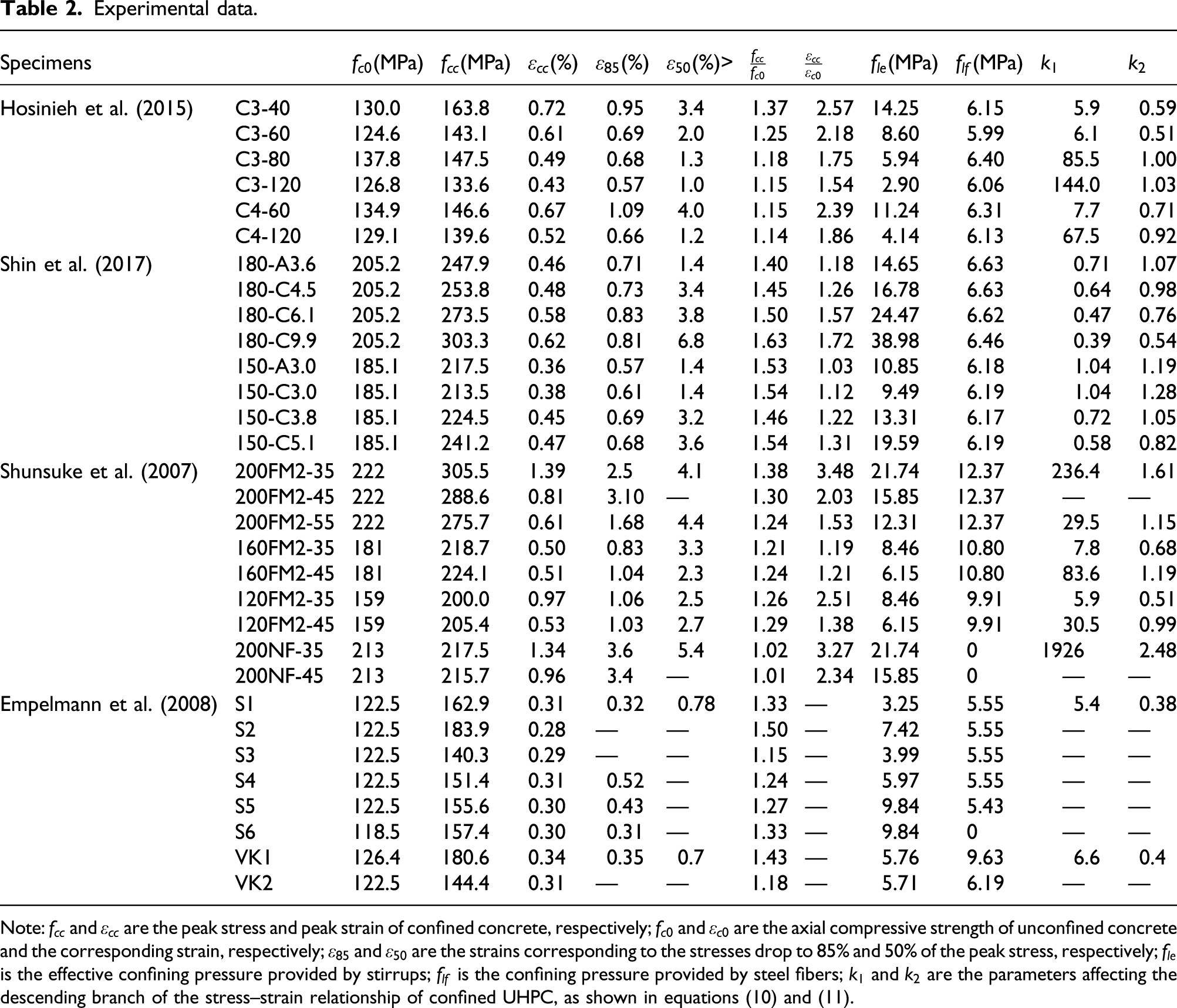
Experimental data.
Note:
The comparison between the results predicted by the models and those of the experiments is shown in Figure 1. The ratio of the predictions to experimental results is evaluated by the average and the coefficient of variation (COV). The proposed peak stress predictions are found to agree well with the test results, and the average and COV values of the ratios are 1.00 and 8.78%, respectively. In contrast, the peak stress predictions of the other models are overestimated. For the models proposed by Mander et al. (1988), Saatcioglu and Razvi (1992), Cusson and Paultre (1995), Aoude (2008), and Shin et al. (2018), the average values of the ratios are 1.16, 1.07, 1.13, 1.32, and 1.07, respectively. The strains predicted by the proposed models considerably differ from the experimental results, and the average and COV values of the ratio are 1.00 and 30.2%, respectively. Despite all this, the proposed expression has a better ability to predict the peak strain compared with the other models. Comparison between experimental and predicted results. (
Formulation of constitutive model
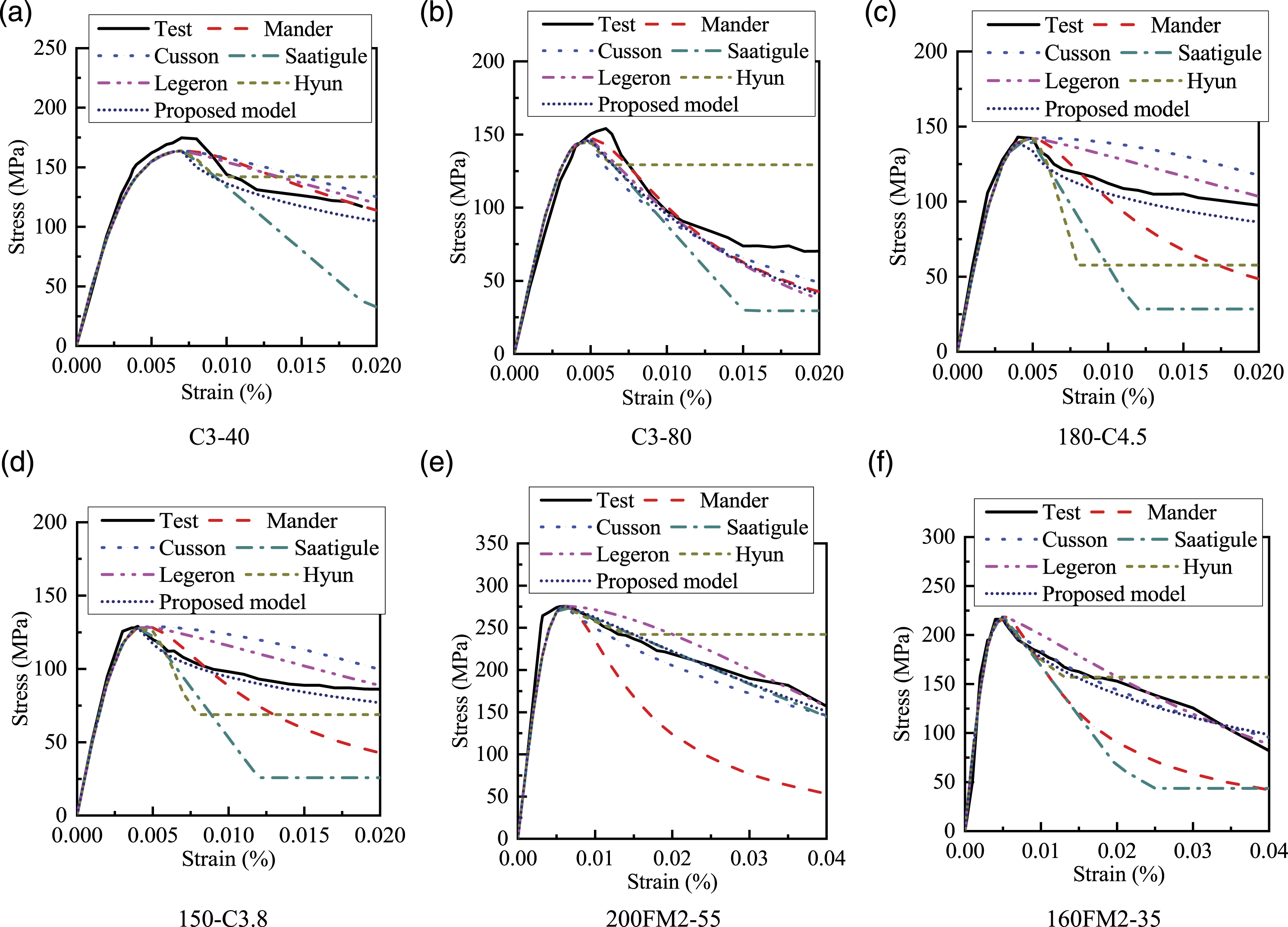
The prediction results of the stress–strain relationship for the confined UHPC by different model are shown in Figure 3. At the ascending branch, the prediction results agree well with the test results. However, the curves obtained by different models are quite different at the descending branch. Hence, the function for the ascending branch in previous researches (as shown in Table 1) is chosen and modified to consider the effect of steel fiber. The function for the descending branch refers to the research done by Fafitis et al. (1985) Comparison between test and prediction results of constitutive models. ( Compression constitutive model of UHPC.






Comparison with other constitutive models
The stress–strain relationship obtained by the proposed model is shown in Figure 3. It is found that the curve obtained by the proposed model agrees well with the test results for all the six randomly selected UHPC columns. The suboptimal models include those of Cusson and Paultre (1995) and Légeron and Paultre (2003), whereas the models of Mander et al. (1988), Shin et al. (2018), and Saatigule et al. (1992) cannot well predict the stress–strain relationship of UHPC.
Finite element analysis
Finite element analysis (FEA) is an important method for evaluating UHPC structures. The nonlinear behavior of UHPC columns was investigated by linking the research results of the concrete damaged plasticity model (CDP) in ABAQUS with the results of the UHPC constitutive model. Because the stirrups are also simulated in the models, the confining effect of stirrups is ignored in the constitutive model of UHPC (i.e., the comprehensive confining coefficient is calculated as
Constitutive model of material
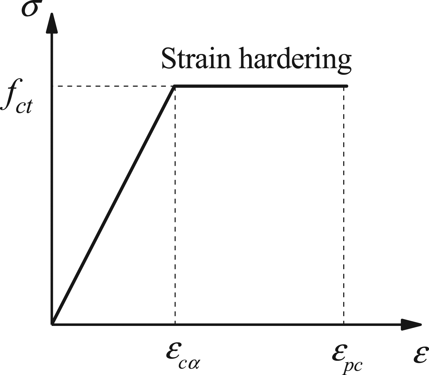
The compression constitutive model of the UHPC is obtained using equations (7) and (8). The tensile stress–strain relationship of the UHPC is shown in Figure 4. The tensile constitutive model of the UHPC is expressed as follows (Wille et al., 2014) Tensile constitutive model of UHPC.

The constitutive model of the stirrup and longitudinal reinforcement follows a bilinear model, as shown in Figure 5. The elastic-plastic model was used to simulate them. Behavior of steel reinforcing bars in tension.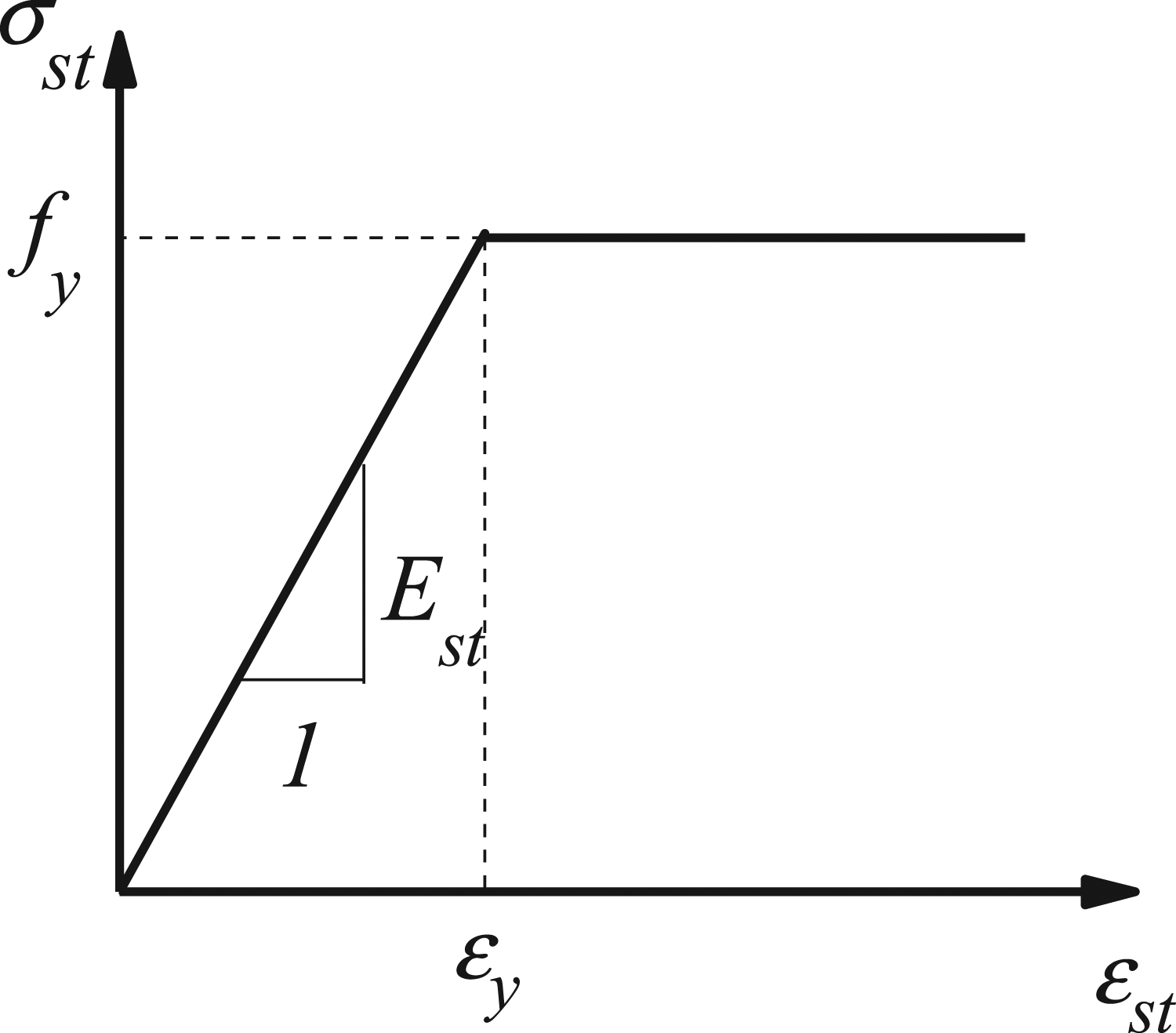
Plastic damage model of concrete
The use of CDP in ABAQUS is suitable for reflecting the plastic deformation and elastic damage of the UHPC. It describes the inelastic behavior of materials by using the isotropic damage parameters as internal variables of the damage model characteristics and combining the elastic-plastic behaviors under tensile and compressive stress.
Plastic material
The critical stress state is defined by the yield surface, and the plastic deformation starts once the critical stress state is reached. The CDP model adopts the yield criterion proposed by Lubliner et al. (1988) and modified by Lee and Fenves (1998) to explain the different strength evolution rules under tension and compression. The two main parameters determining the shape of the yield surface are 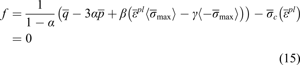



In addition, the direction and size of the plastic deformation are determined according to the flow regularity controlled by the plastic flow potential function. The potential function is related to the expansion angle 
Material damage
For the damaged materials, the effective stress and strain are adopted to present the stress and strain fields corresponding to the damage state. The effective stress, which is the basic core of the continuous damage theory, has been successfully applied to the damage mechanics model.
In the case of the isotropic damage, the effective stress can be calculated as



Stress–strain relationship of compression and tensile damage
The stress–strain curve of the compression damage is shown in Figure 6. According to the classic elastic-plastic theory, the total strain is divided into inelastic and elastic strains to reflect the nonlinearity and irreversibility of the concrete deformation, as expressed in equation (24) Stress–strain relationship of compression plastic damage model.


The equivalent plastic strain, compressive stress, and effective compressive stress are obtained using equations (26)–(28)


Similarly, the total tensile strain is divided into inelastic (cracking strain) and elastic strains, as shown in equations (29) and (30)

The equivalent plastic strain, tensile stress, and effective tensile stress were calculated using equations (31)–(33)


Determination of model parameters
The parameter values of the yield criterion and flow rule in the plastic damage model are determined based on previous research (Curbach and Speck, 2008). The dilation angle parameter reflects the volume change observed in granular materials (e.g., concrete) when it is subjected to shear deformations (Othman and Marzouk, 2018). The dilation angle is in the range of 25–40° for traditional concrete (Genikomsou and Polak, 2015). However, the micro-structure of UHPC is different from other concrete classes, which of properties are improved due to the presence of steel fibers. Based on previous studies done by other researchers and considering the effect of confinement pressure (Curbach and Speck, 2008; Dogu and Menkulasi, 2020), the value of the dilation angle
Model establishment
The C3D8R element type was chosen to model the UHPC. This element provides a reliable solution to both linear and complex non-linear analyses because it has eight nodes, each of which has three degrees of freedom. Consequently, it can accurately simulate the UHPC. The longitudinal and stirrups were modeled using the T3D2 element because they only sustain the axial forces applied to the UHPC columns.
An embedded region constraint was adopted to model the interaction between the steel bar and UHPC. The UHPC was selected as the host region, and the internal steel bars served as the embedded region. Then, a reference point couple was set at the top surface of the model. A fixed constraint was set at the bottom of the model to limit the translational and rotational degrees of freedom in three directions. In additional, it was observed that around 10 mm mesh provides accurate results within reasonable computational time through the mesh convergence analyses. Therefore, the mesh size of 10 mm is adopted.
Comparison with test results
The test results in previous studies done by Sugano et al. (2007) (specimen 160FM2-35), Hosinieh et al. (2015) (specimens C3-120 and C4-60), and Shin et al. (2017) (specimens 150-C3.0, 150-C5.1, 180-A3.6, 180-C4.5, and 150-A3.0) are used to verify the correctness of the modeling methods. The details of the models in this section including the reinforcement details, loading scheme, and boundary condition are the same as that of the specimens in these studies.
Load–displacement curve
The P-Δ curves of eight UHPC columns obtained by tests and FEA are shown in Figure 7. As shown in Figure 7, the FEA results were slightly overestimated compared to the test results in the descending segment. The bond performance between the reinforcement and concrete is accurately assumed in the FEA, whereas the bond performance does not reach the ideal state in the tests. However, the simulation curves do not exceed the test curves in specimens 150-C3.0 and 150-A3.0, which may be caused by the uneven distribution of steel fibers in these specimens. Generally, the FEA model can reasonably track the experimental behavior of the UHPC column. Comparison between simulation and test results. (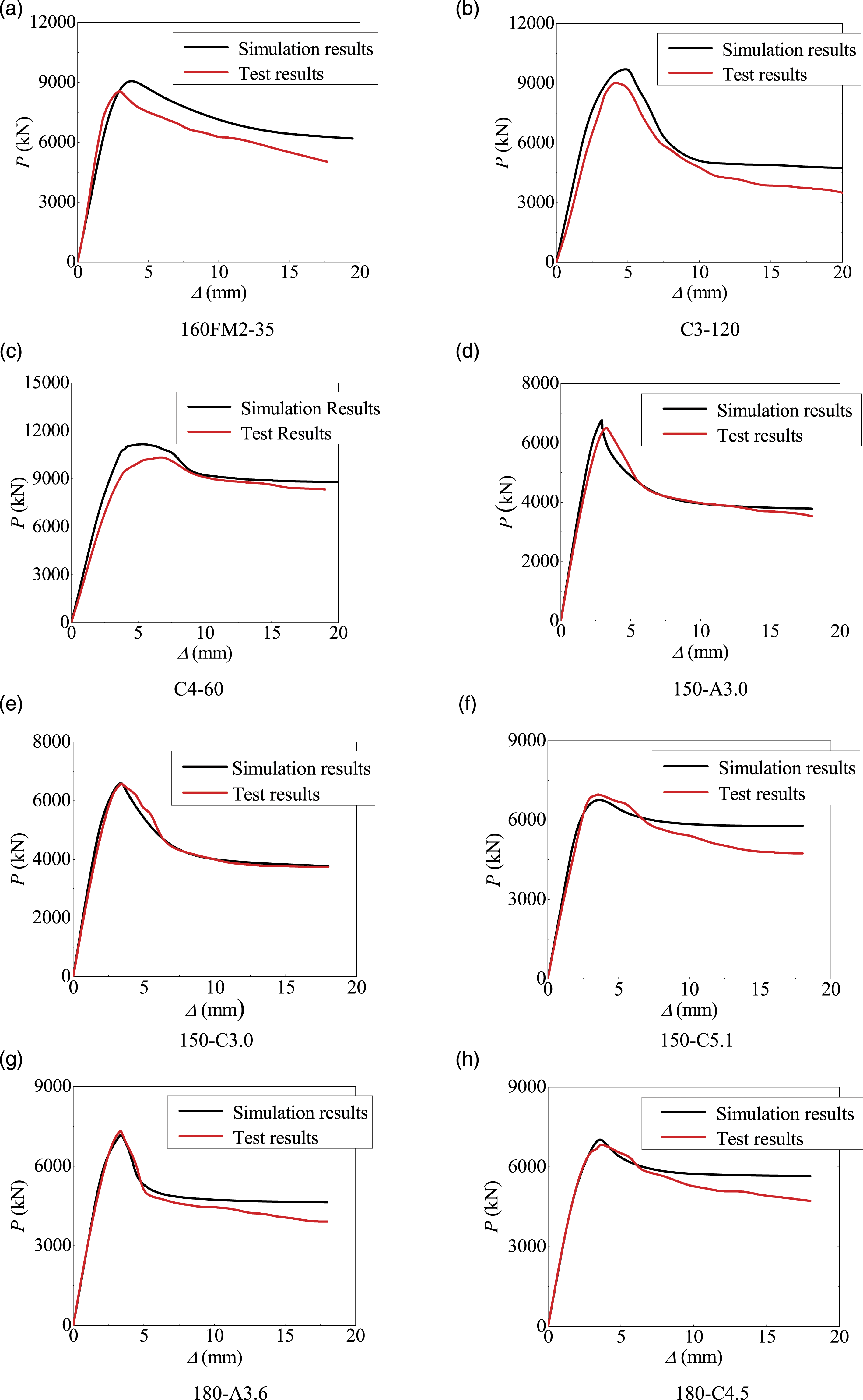
Plastic damage
The proposed constitutive model is applied in the FEA. The plastic damage of two typical UHPC columns is shown in Figure 8. It is indicated that a certain amount of minor damage to the columns initiated after the yielding of the longitudinal reinforcement occurred, and the damage area gradually increased as the displacement continuously increased. Consistent with the test results, the specimens eventually failed in compression. Plastic damage. (
Parametric analysis
Design specimens
Specimen details.
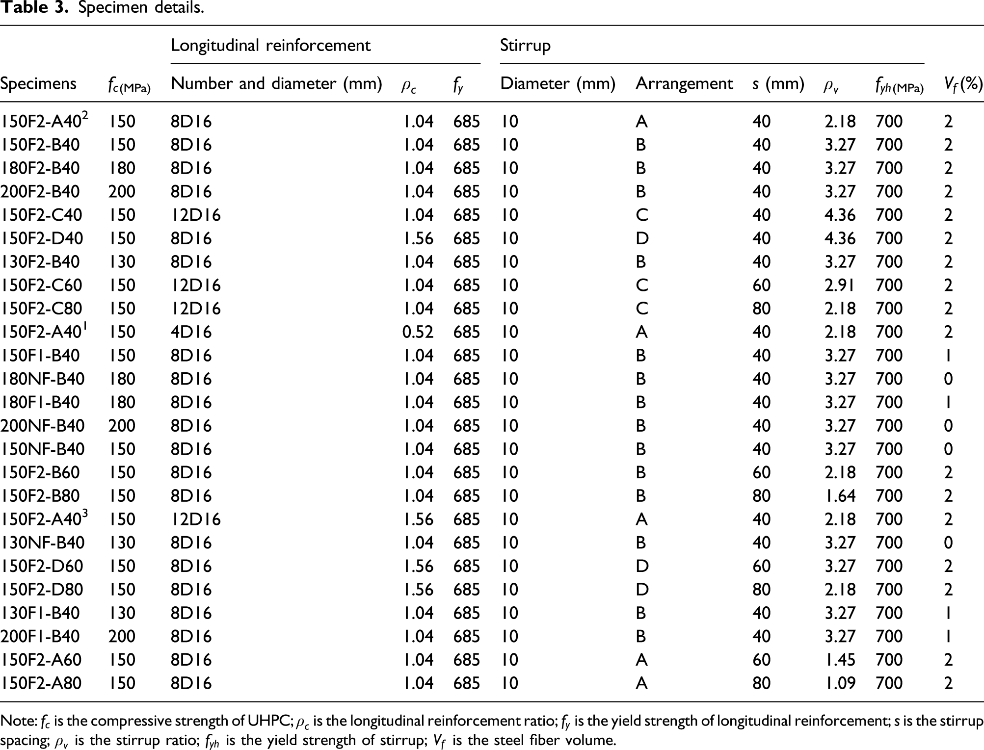
Note:

Stirrup configuration. (
Finite element analysis results
The load versus displacement (P-Δ) curves of all specimens obtained by the FEA are shown in Figure 10. The parameters reflecting the axial behavior of UHPC columns are calculated and summarized in Table 4. The table also lists the peak load, the axial loads borne by the UHPC and confined UHPC, and the corresponding strain and toughness index. The axial load borne by the UHPC is the difference between the load sustained by the longitudinal reinforcement and the peak load of the UHPC column. The definition and calculation method of the toughness index are shown in Figure 11. This index is the ratio of the area surrounded by the concrete load–strain relationship curve up to a strain of 0.02 to the area of an equivalent rigid material P-Δ curves of UHPC column. ( Simulated results. Note: Definition of toughness parameters.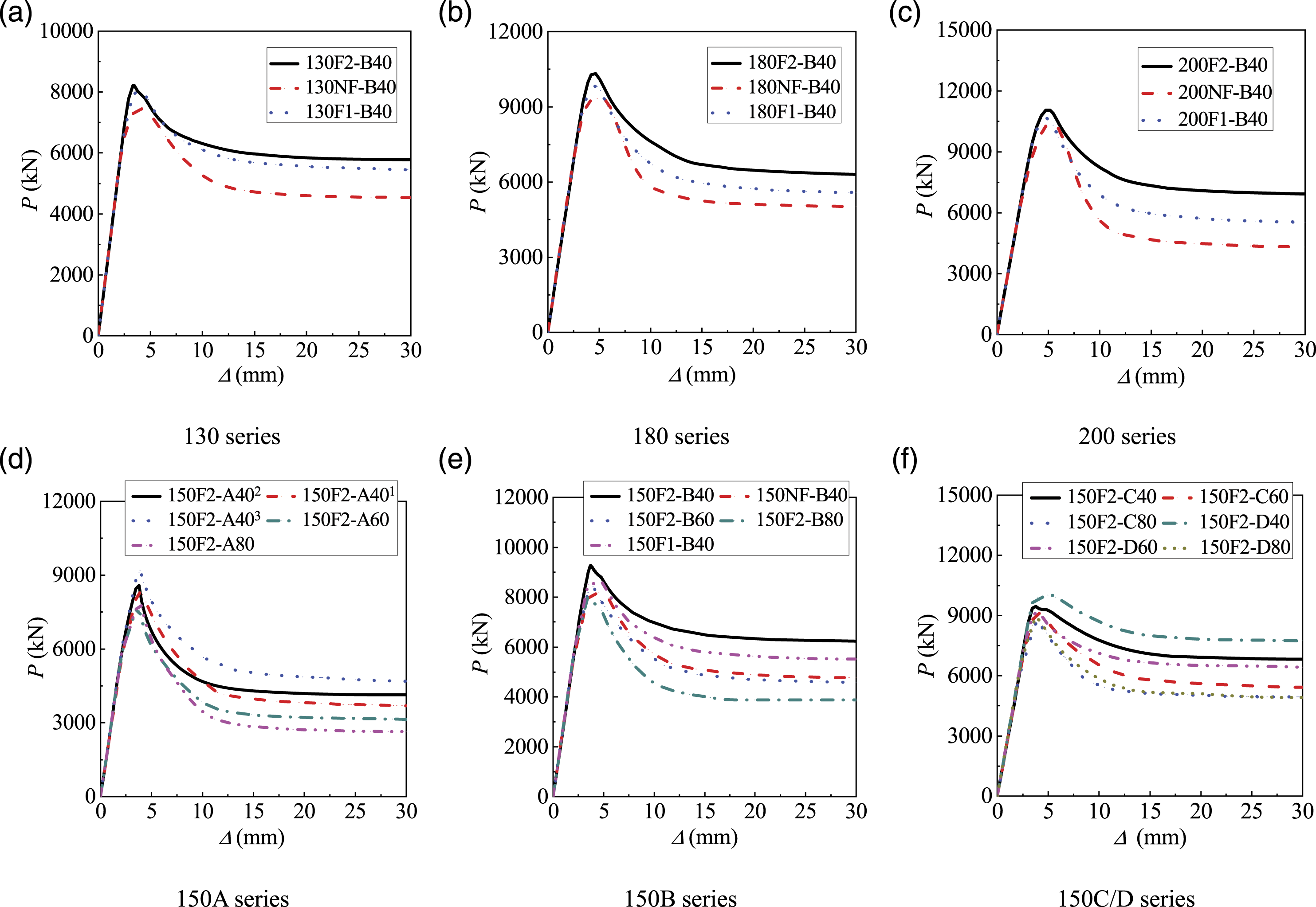
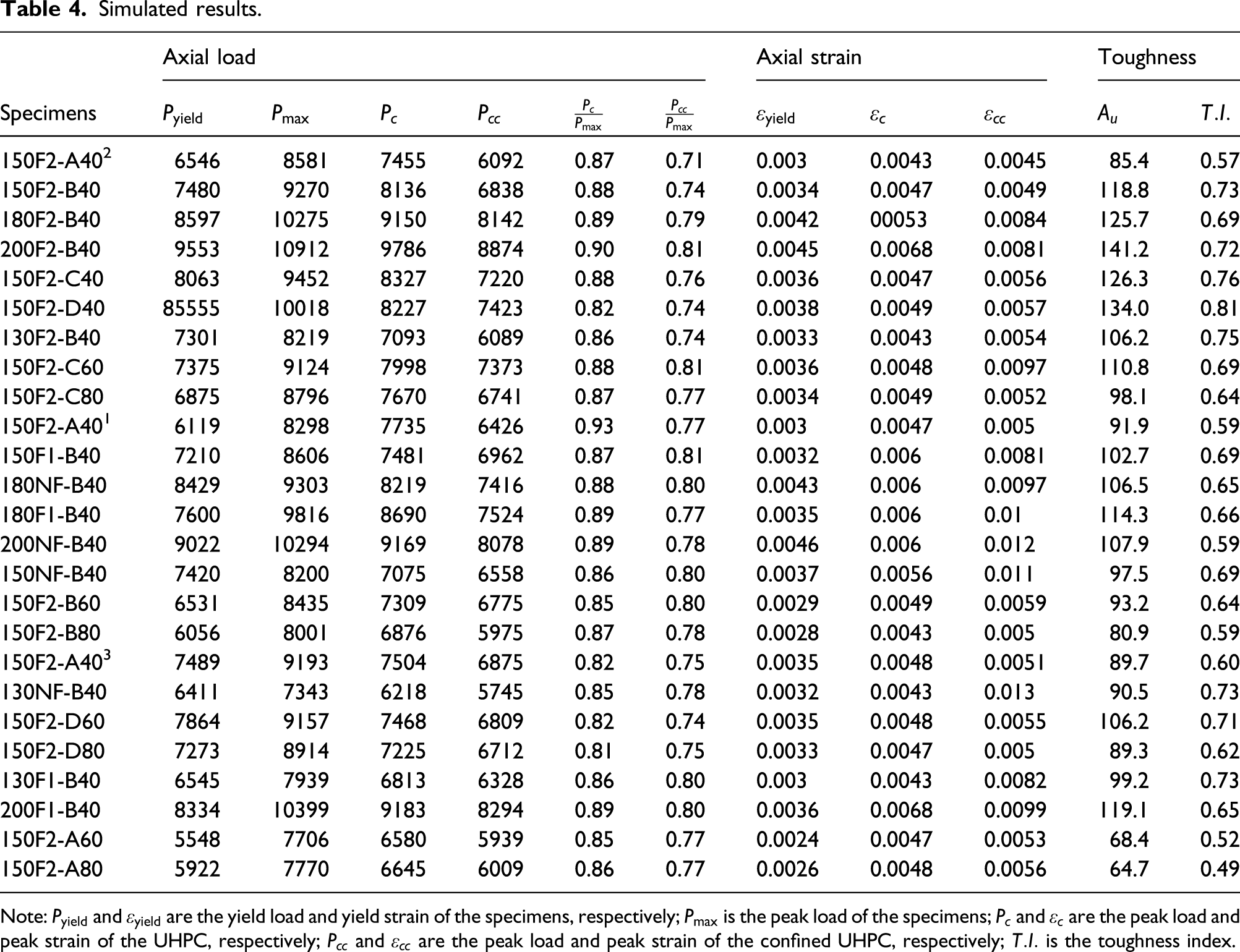

The maximum axial loads of all the specimens range from 7000 to 11,000 kN. Specimen 200F2-B40 has the highest axial bearing capacity because of its higher concrete strength, smaller stirrup spacing, and moderate steel fiber volume. In contrast, specimen 130NF-B40 has the lowest axial load. The axial compressive behavior of UHPC column is the combination of the contributions of the confined concrete, cover concrete, and longitudinal reinforcement. The average values of
Variable analysis
The parameters influencing the behavior of UHPC columns investigated in the article include the (1) stirrup spacing (s = 40–80 mm), (2) stirrup configuration (A, B, C, and D), (3) steel fiber volume (V f = 0–2%), and (4) longitudinal reinforcement ratio (ρ c = 0.52–1.54%). The control variable method is employed to investigate the influence of the parameters on the UHPC column performance.
(1) Influence of stirrup spacing
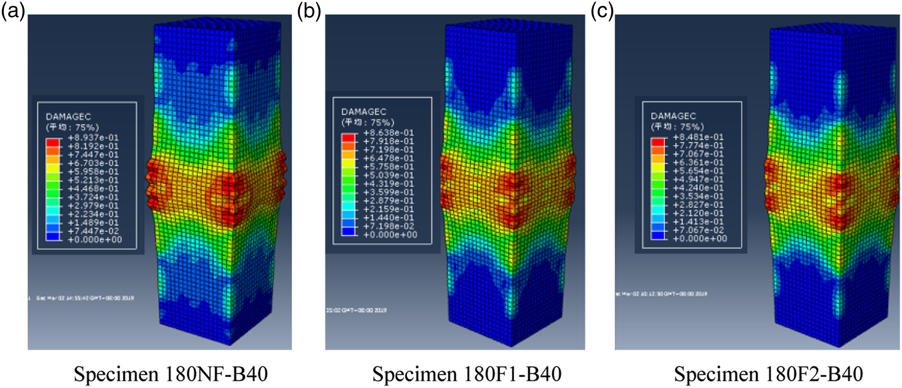
The influence of stirrup spacing on the load–displacement relationship curves of the UHPC column is shown in Table 4 and Figure 12. With the decrease in the stirrup spacing, the post-ductility of the UHPC columns significantly improves and the peak load also increases to a certain extent. The plastic damage is shown in Figure 13. A local failure resulting from the large spacing of the stirrup and weak protection of concrete could be observed in the middle of the column shown in Figure 13(c). By contrast, specimen 150F2-D40, which has closely spaced stirrup, exhibits better performance. This indicates that reducing the stirrup spacing significantly improves the UHPC column performance. Load–displacement responses corresponding to different stirrup spacings. Plastic damage of the UHPC columns with different stirrup spacings. (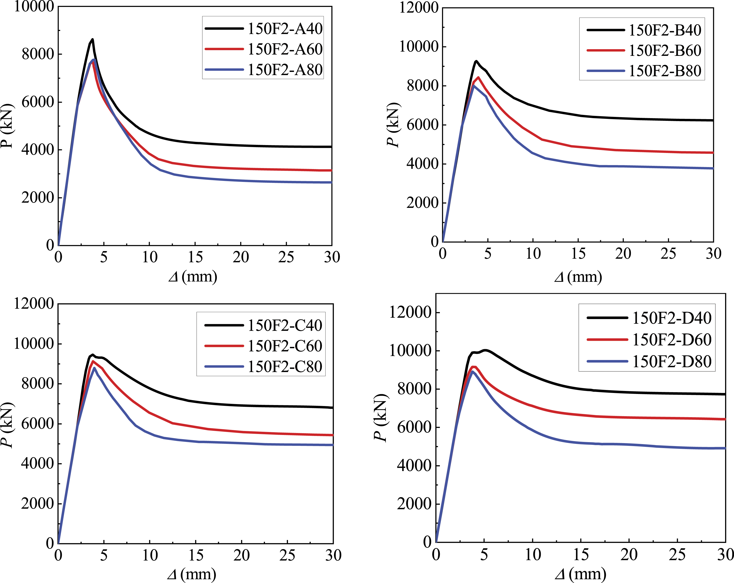

(2) Influence of stirrup configurations
The influence of stirrup configuration on the load–displacement relationship curves of the UHPC column is shown in Table 4 and Figure 14. It is evident that by improving the cross-sectional details, the stirrup configurations change and the peak load correspondingly improves. In addition, the curves of the four specimens show that the strength degradation after the peak load becomes more moderate with the enhancement of the cross-sectional details, indicating that the ductility significantly increases. The plastic damage is shown in Figure 15. It is evident that the damage of these columns considerably decreases with the improvement of the cross-sectional details. Load–displacement responses corresponding to different stirrup configurations. Plastic damage of the UHPC columns with different stirrup configurations. (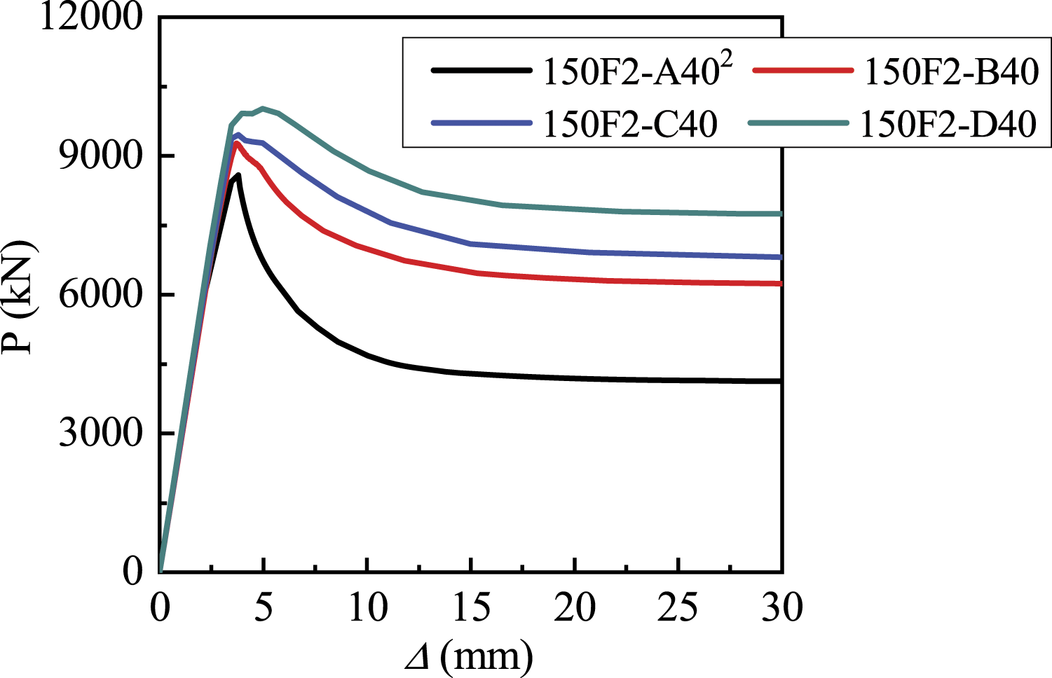

(3) Influence of steel fiber volume
The influence of steel fiber volume on the load–displacement relationship curves of the UHPC column is shown in Table 4 and Figure 16. The performances of these columns are improved because of the presence of steel fibers. The peak load gradually increases as the concrete compressive strength increases from 130 to 200 MPa. The plastic damage is shown in Figure 17. It is found that the damage area significantly decreases as the steel fiber volume increases. The improvement in the performance of the UHPC columns is more distinct when the steel fiber volume increases from 1 to 2%. Load–displacement responses corresponding to different steel fiber volumes. Plastic damage of the UHPC columns with different steel fiber volumes. (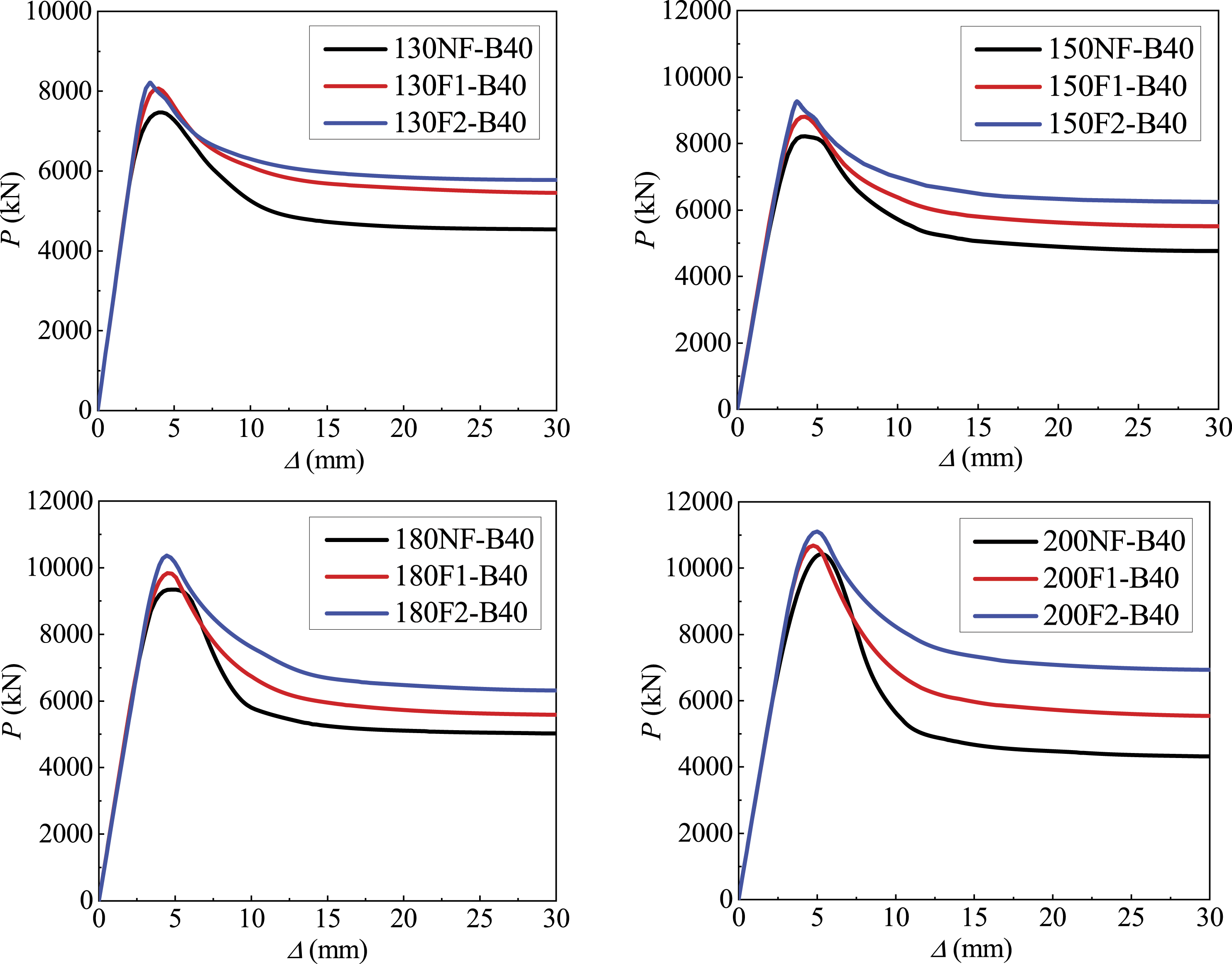
(4) Influence of longitudinal reinforcement ratio
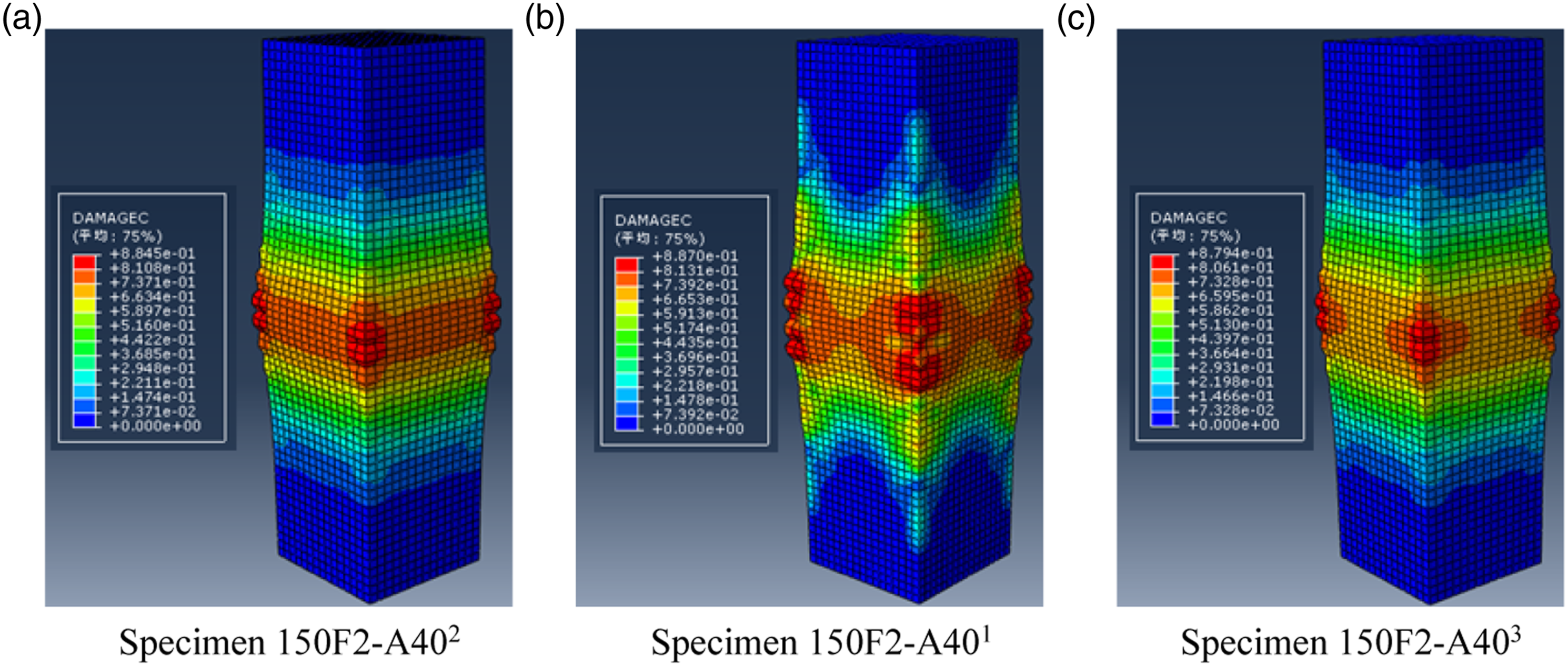
The influence of longitudinal reinforcement ratio on the load–displacement relationship curves of the UHPC column is shown in Table 4 and Figure 18. Increasing the longitudinal reinforcement ratio from 0.52 to 1.04 and 1.57% also increases the peak load by 3.4 and 10.8%, respectively. Although the toughness improved, the effect of longitudinal reinforcement ratio on ductility was not significant. The plastic damage is shown in Figure 19. Because the longitudinal reinforcement ratio decreases, the local failure of UHPC columns occurs and the embedded reinforcement in specimen 150F2-A402 buckled. Therefore, the minimum reinforcement ratio should be controlled during the design of UHPC columns to prevent the premature buckling of the longitudinal reinforcement. Load–displacement responses corresponding to different longitudinal reinforcement ratios. Plastic damage of the UHPC columns with different longitudinal reinforcement ratios. (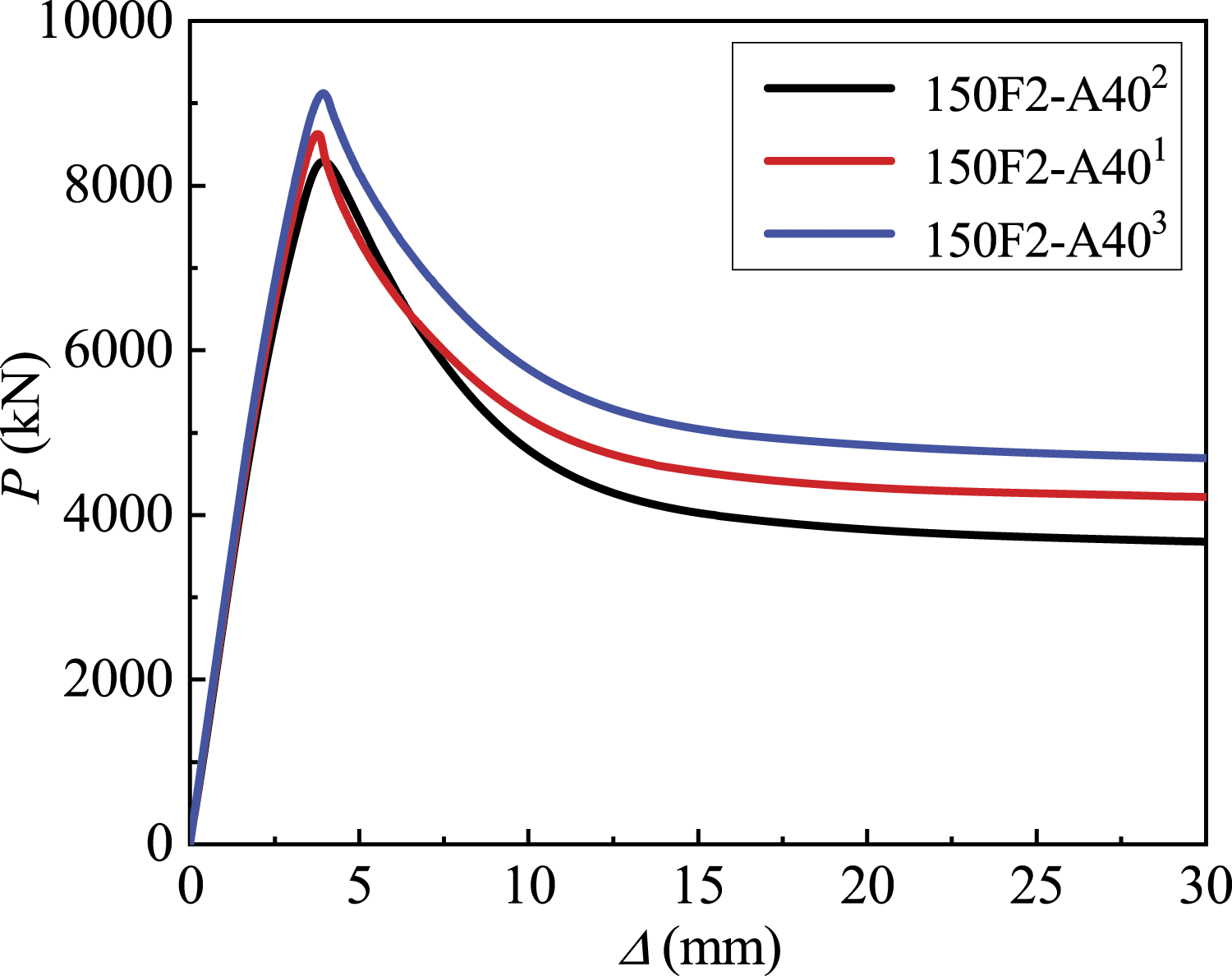
Conclusion
A confined UHPC constitutive model was proposed based on the collated test data and statistical analysis. This model was further applied to FEA. It was indicated that the model accurately predicted the behavior of UHPC columns as evinced by the comparison with test results, as well as the plastic damage analysis and load–displacement response. Accordingly, this provides a reference for the subsequent FEA of UHPC columns. In addition, the influences of stirrup spacing, stirrup configuration, steel fiber volume, and longitudinal reinforcement ratio on the axial compressive behavior of UHPC columns were analyzed by FEA. The following conclusions were drawn. (1). A confined UHPC constitutive with the consideration of the confinement provided by steel fiber and stirrup was developed. This model was then used in FEA, in which the plastic damage to concrete, material properties of steel bars, interaction between concrete and steel bars, and boundary conditions of the UHPC columns were considered. By comparing with the tested results, it was demonstrated that the FEA model reasonably predicted the axial compressive behavior of UHPC columns and the proposed constitutive model can be implemented in the FEA software. (2). The response of UHPC columns subjected to axial loading can be recognized as the combination of the contributions of the confined concrete, cover concrete, and longitudinal reinforcement. The UHPC, especially the confined UHPC, performed a key role in improving the performance of the UHPC columns. The stirrup spacing, stirrup configuration, and steel fiber volume were important factors affecting the ductility of UHPC columns. (3). The ductility of the UHPC columns was significantly improved by reducing the stirrup spacing and improving the cross-sectional details. The improvement in ductility was more considerable when the steel fiber volume was 1–2% than when it was 0–1%. Additionally, although the effect of the longitudinal reinforcement ratio on ductility was not significant, it was necessary to control the minimum reinforcement ratio in the design of UHPC columns.
Footnotes
Declaration of Conflicting Interests
The author(s) declared no potential conflicts of interest with respect to the research, authorship, and/or publication of this article.
Funding
The author(s) disclosed receipt of the following financial support for the research, authorship, and/or publication of this article: This work was supported by the National Natural Science Foundations of China No. 51908041 and the Fundamental Research Funds for the Central Universities No. 31088171009.
