
Abstract
Bearing flatness is a critical for the construction quality inspection of highway and railway bridges during construction. Conventional methods may result in high costs, operational safety risks and low measurement efficiency for high bridge piers in mountainous terrain. To address these issues, this paper developed an innovative quadcopter drone with an optical prism target for rapid and automated measurement of bearing flatness. The contribution of this study includes two aspects: (1) An optimized YOLO-MiniFaster model is developed for bearing padstones detection based on the RepNCSPGELAN module, the Slim-FPN feature fusion architecture, and SimAM attention mechanism. This enhanced architecture enables real-time and accurate detection of bridge bearings with higher computational efficiency. (2) A custom hardware prototype is developed, consisting of a quadcopter drone platform, an optical target module, a high-resolution image acquisition unit, and flight control system. The effectiveness of the developed drone system has been validated through field tests of a newly constructed railway bridge. Experimental results demonstrate that the developed model achieves a mean average precision (mAP) of 87.14% in detecting the bridge bearing padstones with a 14.3% reduction in model parameters compared to the original model. Furthermore, the quadcopter drone system enables a 45% reduction in on-site operational time compared to traditional manual methods. The developed system offers an alternative method that could improve the operational safety and measurement efficiency for bridge construction in hard-to-access locations.
Introduction
Bridges are indispensable components of transportation infrastructures, which facilitate the extension of existing roads across geographical barriers (e.g., river valleys and gorges) (Cho et al., 2014; Freire et al., 2013). Bearings connect the superstructures to the substructures of the bridge systems, which enables the reliable transfer of structural loads. The performance of these bearings is crucial to the longevity and structural integrity of bridges, as bearing failures would result in geometric deformation ,stress redistribution and even collapse (Adamou et al., 2021; Aria and Akbari, 2013; Freire and De Brito, 2006; Niemierko, 2016). Therefore, it is important to measure the geometric deviation and flatness of bearing padstones for the construction quality and operational safety of numerous bridges in highway and railway roads.
Existing measurement techniques for bridge bearings are classified into contact and non-contact approaches. Traditionally, contact instruments such as dial gauges, hydraulic transduction devices, and electromechanical deformation sensors, are widely used to measure the construciton quality of bridge bearings (Freire et al., 2014). The triangulation method that employs total stations and optical leveling tools is a conventional noncontact quality control technique for bridge construction quality control. However, these traditional methods are often limited by low operational efficiency. With the advancements of modern technologies, various advanced non-contact measurement systems have been developed recently, such as computer vision-based techniques (Hong et al., 2024; Su et al., 2023; Wang et al., 2025), magnetorheological fluid sensing (Behrooz M et al., 2016), laser triangulation systems (Artese et al., 2018), and interferometric radar (Lamperová et al., 2020). These emerging technologies are considered as the next-generation methods that can control the contruction quality of bridges.
The planar alignment of bearing components is important for bridge construction quality assessment. In practical engineering, padstones are designed as reinforced concrete members to transfer structural loads and maintain the position of bearings, which are typically placed on the bridge bearings (Li et al., 2014; Ma et al., 2022; Qiao et al., 2021). The surface flatness of these padstones directly has a direct ompact on the pressure distribution of bearings, resulting in localized stress concentrations and differential settlement (Yahya et al., 2020). The padstone flatness is a key quality control indicator affecting the construction safety and long-term operational safety. As a result, accurate measurement of the bearing surface flatness of the bridges is essential for ensuring the structural integrity over their designed service life. Conventional methods use crane to assist the worker to the target bridge piers and place the prisms on padstones and then measure with a total station or differential leveling instrument. Although this method is feasible for short bridge piers, it has limitations in terms of measurement efficiency and spatial accuracy when applied for high bridge piers in complex environments with limited accessibility to crane machinery.
The advancement of robotic systems and unmanned aerial vehicles (UAVs) have revolutionized bridge inspection procedures in recent years (Jurica et al., 2023). Robotic platforms with multi-sensor setups (e.g., stereo cameras, LiDAR) facilitate comprehensive quality control and condition assessment of bridges. For example, Peel et al. (2018) developed an adaptive robotic system for bridge bearing inspection, which addressed the challenge of spatial constraints by quantitatively monitoring geometric deformations under limited field-of-view conditions. Mnay studies have systematically examined various application cases, for example, robotic positioning for bridge bearing inspections, automated defects detection using wheeled robots, and extracting depth information for crack detection with photogrammetric camera systems (Abdoli et al., 2024; Oh et al., 2007; Rossow, 2006). Lattanzi and Miller (2015) and Mazumdar and Asada (2009) have developed a camera-mounted robotic platforms for crack detection on bridge components; Meng et al. (2023) developed an intelligent robotic inspection system with deep learning algorithms for defect classfication; Antonio et al. (2022) developed a multifuncational robotic platforms for mapping, positioning, and inspection of bridges. In addition, various drone platforms have been developed for bridge inspection. For example, Dominik et al. (2020) optimized the deployment strategy of UAV for bridge inpseciton; Wang et al. (2023b) developed operational strategy of UAV systems for bridge inspections under wind environments; Sainab and Saleh (2021) evaluated drone-integrated remote sensing technologies (visual, infrared, LiDAR) for structural data acquisition; Mostafa et al. (2021) used a drone-installed camera to examine the underside conditions of bridges. However, there is research gap in the development of an automatic drone system for rapid flatness measurement of bearing padstones.
Therefore, this study proposes a drone-based measurement system for rapid bearing flatness measurement of bridges under construction with deep learning-based object detection model. The structure of the paper is as follows: Section 2 describes the developed drone-based system, including the overall framework, the lightweight YOLO-MiniFaster model for bearing detection, and its hardware development . Section 3 describes the dataset construction and model training procedures. Section 4 validates the robustness of the developed system through field tests conducted on a real-world bridge. Conclusions and future work are presented in Section 5.
Proposed methodology
Framework
The overall framework of the developed system for bearing flatness measurement of bridges is illustrated in Figure 1. A drone with prism targets takes off from the ground and flies to the specified bridge pier, while transmitting video images from the drone camera to a lightweight deep learning model (Liang et al., 2024; Wang and Su, 2023a). The pre-trained neural network is used to process this data to identify the quantity and spatial coordinates of padstones on the bridge pier for automatic path planning. In each predetermined navigation node, the drone makes real-time adjustments to its position based on the centroid coordinates of each padstone. Once optimal alignment above the target padstone has been achieved, the system enters a controlled descent process with effective environmental feedback. A robotic total station is then used to measure the height of each padstone in millimeter-level accuracy. After the acquisition of elevation data at one bearing padstone, the drone moves to the next padstone. Compared with manual methods, this system significantly improves the efficiency and safety of construction quality inspection in hazardous mountainous areas. Framework of the developed bearing flatness measurement method.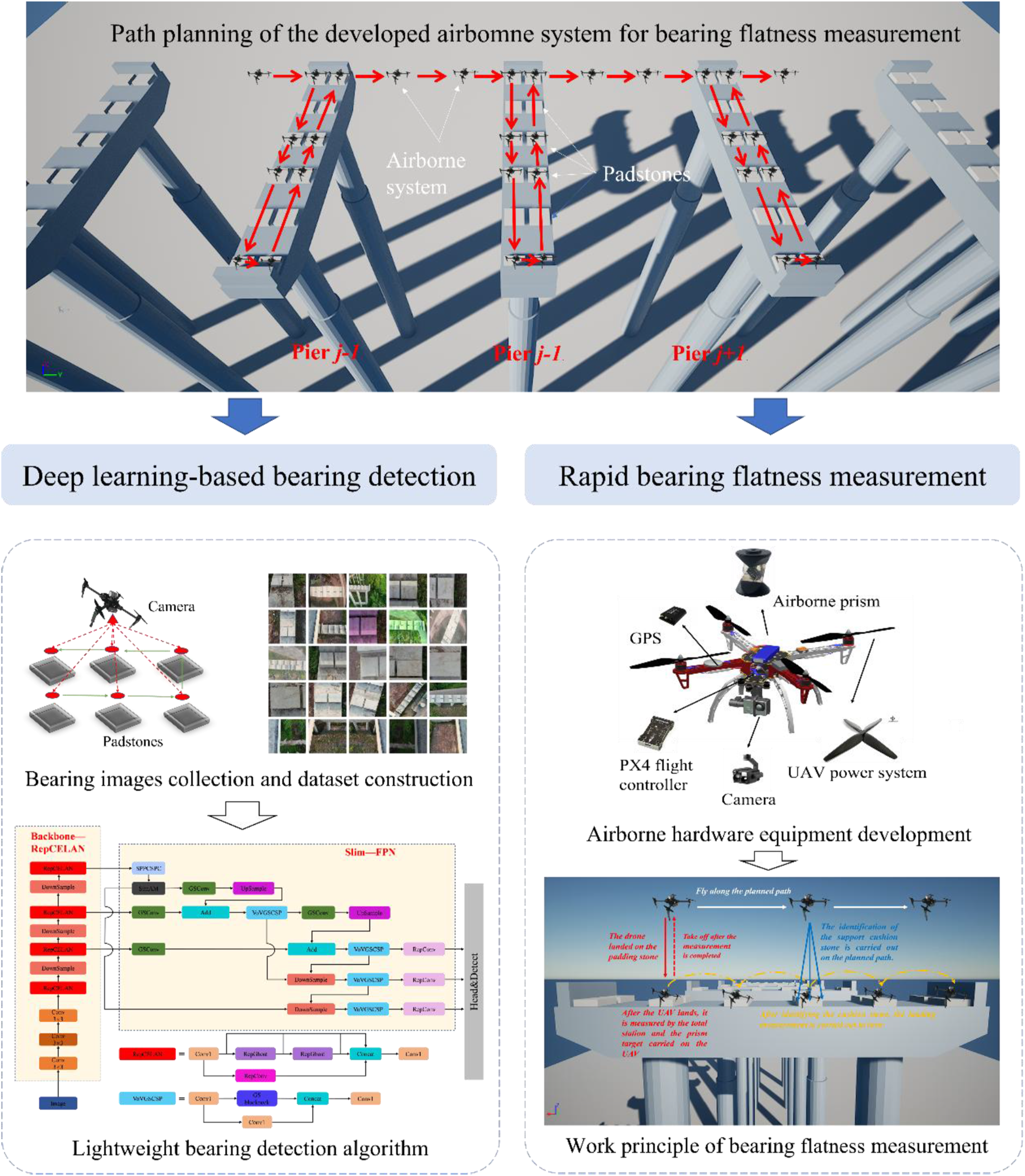
Developed lightweight YOLO-MiniFaster model for bearing detection
Vision navigation is the basis of the path planning and landing control of the drone operation. Once the bearing padstone images are captured by the drone-installed camera, the image data is processed by deep neural networks with high computational efficiency and accuracy. This model is built on the YOLO-MiniFaster architecture (Figure 2), which integrates three core components: the RepNCSPELAN backbone, Neck-FPN fusion network, and SimAM lightweight attention mechanism. To maintain real-time performance, the network depth is optimized to minimize the model parameters and computational costs to ensure minimal detection accuracy loss. Architecture of the developed YOLO-MiniFaster model.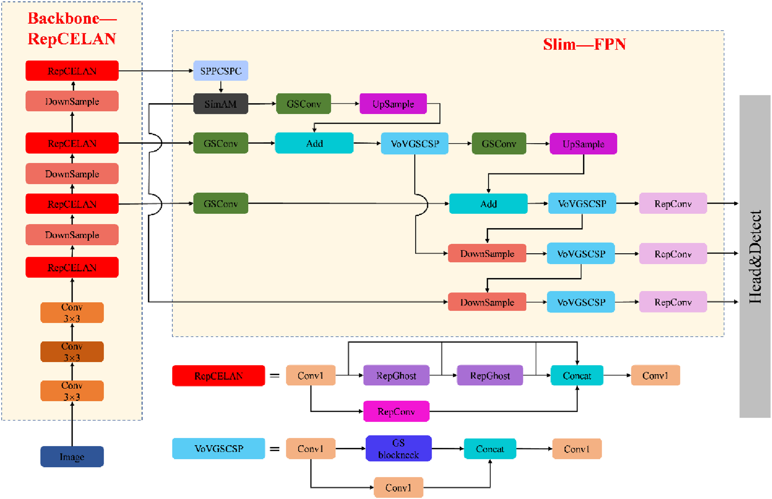
The selection of YOLOv7 as baseline architecture for model optimization was motivated by two pieces of evidence relevant to the technical and operational requirements. First, YOLOv7 is more mature and stable than YOLOv8. Second, the modular design of YOLOv7 allows easy integration of task-specific improvements to customize it for bearing padstone detection. The architecture of the YOLO-MiniFaster model are explained as follows:
Lightweight RepCELAN modules in the backbone network
As illustrated in Figure 3(a), the proposed backbone network uses a three-stage feature extraction pipeline to process input image data. In the first stage, the input image with 640 × 640 × 3 domensions is embedded in a convolutional layer to downsample the image data. The second stage incorporates the result feature map into multi-level deep learning modules that gradually reduce spatial resolution and extract high-level features. The third stage has two side-output branches, which use DownSample and RepCELAN modules to create scale-specific prediction feature maps, enabling parallel processing of multi-scale features and synchronous prediction. Schematic diagram of the Backbone-RepCELAN structure (a) structure of the designed Backbone-RepCELAN model; (b) structure of the RepCELAN block; (c) RepGhost module.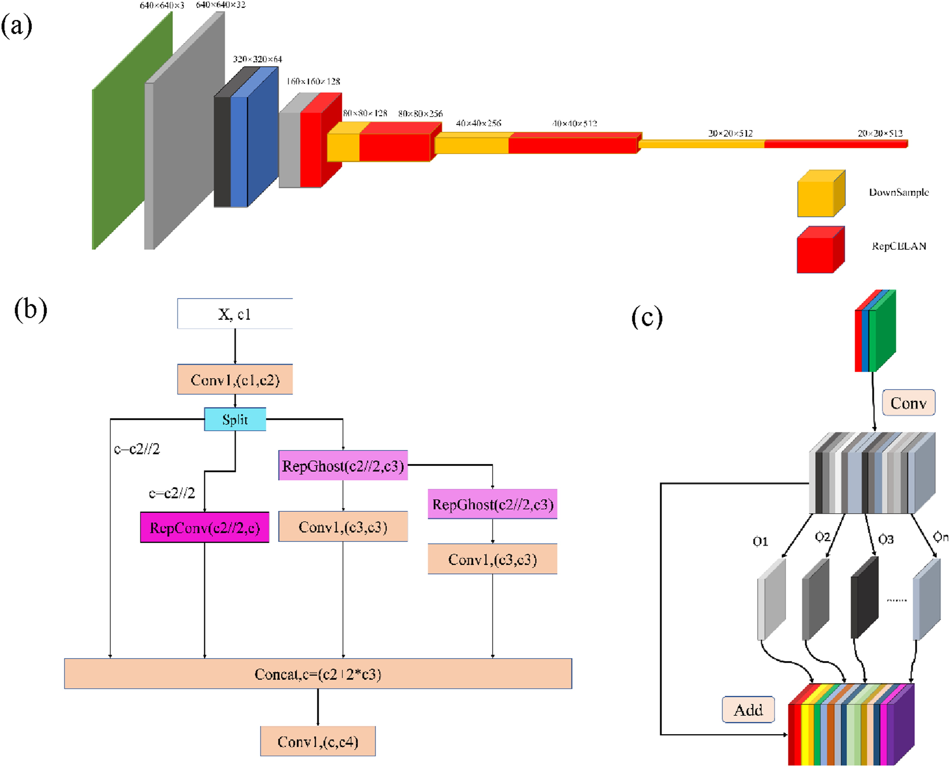
The RepCELAN module employs a symmetric channel-splitting strategy with a 1:1 ratio to balance computational load and feature diversity. Specifically, an initial 1 × 1 convolution layer projects input channels from c1 to c 2 , after which the feature map is evenly partitioned into two subsets, each containing c 2 /2 channels. The first subset is processed by a RepConv branch, which maps c 2 /2 channels to c channels. RepConv employs a multi-branch architecture during the training phase, which is subsequently reparameterized into a single convolution layer during inference The second subset is routed to two parallel RepGhost branches, each projecting c 2 /2 channels to c 3 channels, followed by a 1 × 1 convolution layer for channel refinement. RepGhost exploits ghost feature expansion to generate redundant feature maps with minimal computational cost (Chen et al., 2022).
The output feature maps from the RepConv branch (c channels) and the dual-path RepGhost branch (2c 3 channels) are concatenated into a fused feature tensor of c + 2c 3 channels. The representations are then fused and mapped to c 4 channels via a 1 × 1 convolution layer. The integrated design in this setup balances channel allocation, implements expressive lightweight feature extraction, and enhances feature diversity with parallel processing paths. By replacing the a RepNCSP module with RepGhost into the RepCELAN architecture, two distinct advantages arise. First, RepGhost employs a lightweight “trunk–branch” strategy, where a minimal number of convolutional operations create base feature maps and linear transformations are then performed to produce redundant but information-rich features. This mechanism achieves a significant reduction in computation complexity and parameter quantity while retaining important feature information to improve inference efficiency without compromising detection performance. Second, RepGhost fuses features through element-wise addition through a multi-pathway strategy, which enhances the representational capabilities of shallow feature maps. This mechanism improves feature diversity without increasing network depth and structural complexity of the model, enabling the extraction of fine-grained textures and edge details for small-object detection. Furthermore, RepGhost employs a multi-branch architecture to maximize the expressive power of the features, which is then reparameterized as one convolution layer during inference. This design achieves a good balance between detection accuracy and computational efficiency.
Compared to the original Ghost module, RepGhost replaces channel-wise concatenation (Concat operation, equation (1)) with element-wise addition (Add operation, equation (2)). As described in equation (1), the concat operation combines feature maps with the channel dimension, creating a fused feature map (H, W, 2C) from two input maps (H, W, C). In contrast, the Add operation in equation (2) fuses feature maps that have the same channel dimensions, producing an output shape of (H, W, C). The output channels are halved when using the Add operation. Since the dimensions at the Add operation are consistent, therefore the computational complexity is less compared to Concat, thus accelerating the inference speed.
The integration of RepGhost into RepCELAN enhances computational resource usage and increases feature representation diversity. This change makes the improved RepCELAN module suitable for real-time detection tasks with high-precision and low-latency, which is important for resource-constrained intelligent systems.
Furthermore, this approach is useful in feature fusion which is helpful for enhancing feature extractions and fusion. Recocating the ReLU activation function to the Add operation is consistent with the principles of structural reparameterization, thereby improving inference speed. In the inference stage, RepGhost is compatible with deformable convolution along with an activation function. This combines hardware compatibility and inference efficiency while decreasing model parameters and computational costs. This iterative operations allows reparameterized features to continue generating feature maps. Eventually, feature maps from all branches are concatenated via the Concat operation and then processed by a 1 × 1 convolution layer to modify the number of output channels.


Slim-FPN feature fusion module
Following the refinement of the RepCELAN backbone network, a lightweight Slim-FPN feature fusion module is employed to replace the original YOLOv7 Neck module. The conventional Neck module composed of ELAN and CSB module sgenerates effective generic feature aggregation but is incapable of achieving the required accuracy for bearing padstone detection. Specifically, the dense convolutional stacks of ELAN have a high computational cost and CSB’s residual aggregation mechanism is not specifically designed for the multi-scale fusion of small and low-contrast targets.
To address this problem, the original FPN is optimized by replacing the ELAN and CSB modules with GSConv and VoVGSCSP modules, respectively (Li et al., 2024). This redesign is motivated by two key technical advantages. First, GSConv starts with the decomposition of the standard spatial convolution into a global channel shuffle operation and depthwise convolution (DWConv). Through this decomposition step which is quite effective at removing redundant computation by up to 50% while preserving crucial cross-channel feature interactions. Second, VoVGSCSP uses One-Shot Aggregation (OSA) via split-merge operation, which enhances feature diversity and fine-grained detail representation. This mechanism is beneficial for capturing low-contrast small targets using hierarchical feature integration.
The optimized Slim-FPN architecture has a more lightweight structure and faster inference speed while maintaining detection accuracy, satisfying the practical requirements of drone inspection systems. The entire architecture of the Slim-FPN is illustrated in Figure 4(a), while the implementation details of GSConv and VoVGSCSP are shown in Figure 4(b) and (c), respectively. In GSConv, redundant channels of local feature maps are first downsampled with a 1 × 1 convolutional layer. Next, DWConv is applied to a small subset of the downsampled features to efficiently learn spatial information. The feature maps are concatenated and integrated through a channel shuffle operation to mitigate the correlation between channels, enhance multi-scale feature fusion and improve the computational efficiency. According to VoVGSCSP, the feature aggregation begins with a 1 × 1 convolution layer to adapt channel dimensions and suppress redundant information, which offers an efficient foundation for feature fusion operations. Architecture of the proposed Slim-FPN (a) overall architecture; (b) GSConv module; (c) VoVGSCSP module.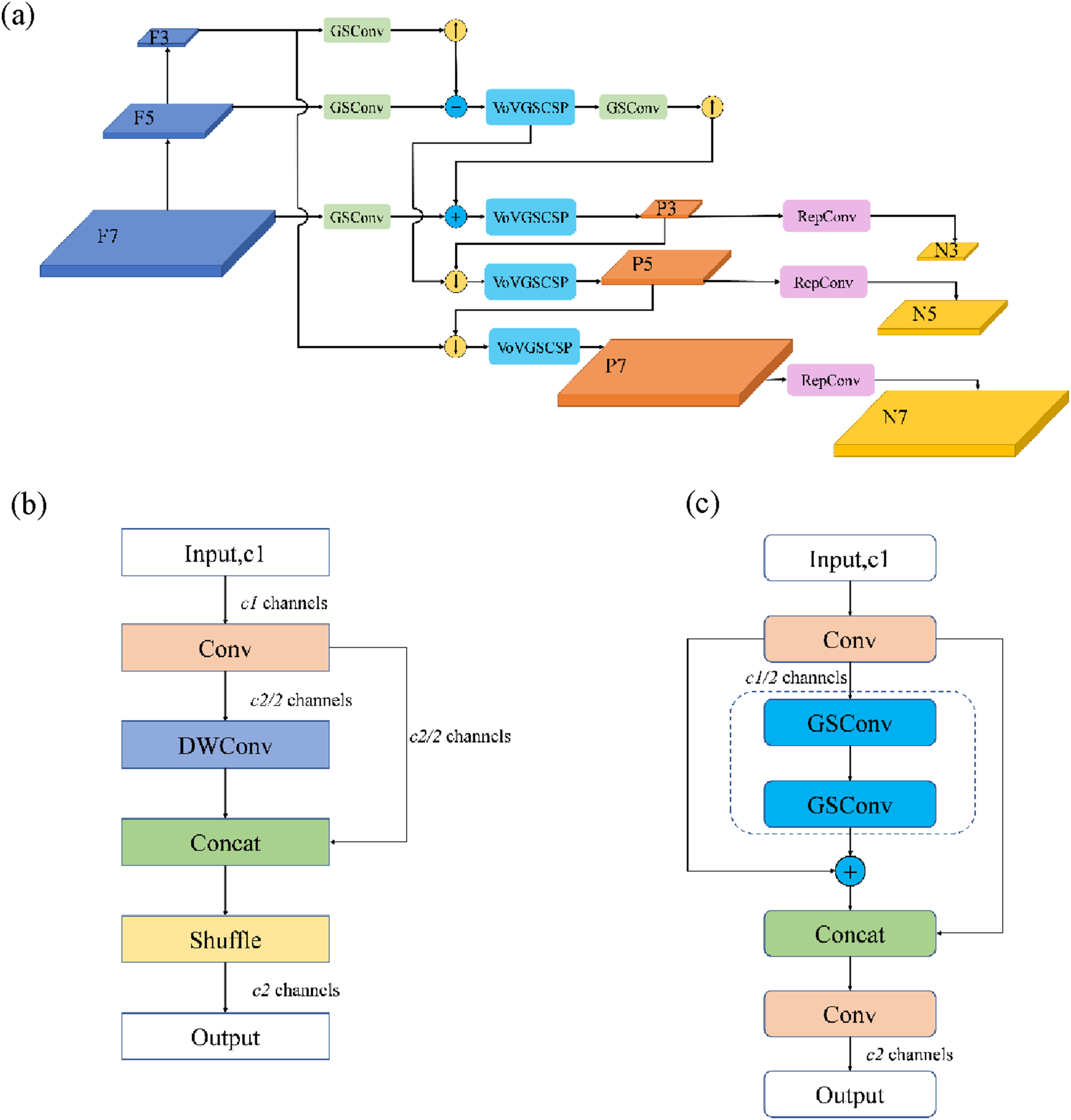
The implementation of the Slim-FPN feature fusion network is described in this section. Specifically, the ELAN and CSB modules of the YOLOv7 Neck module are replaced with GSConv and VoVGSCSP modules, respectively. The Slim-FPN architecture employs a multi-branch fusion strategy. One branch processes features through two cascaded GSConv modules, while the other performs feature addition with an element-wise addition (Add) operator. The outputs of these two branches are concatenated with a segment of features, which is followed by a 1 × 1 convolutional layer used to adjust the output along the channel dimension to eliminate dimensional redundancy. Integrating the GSConv and VoVGSCSP modules into the native FPN-PAN structure of YOLOv7, a Slim-FPN feature fusion network is constructed with an emphasis on detection accuracy and computational cost.
In this modified architecture, the conventional Convolution-Batch Normalization-SiLU (CBS) modules in the original Neck was replaced with GSConv modules. Feature maps of large, medium, and small sizes are extracted from the RepCELAN backbone and then fed into GSConv modules that enhances feature representation via upsampling. Then, produced feature maps are summed with complementary scale feature maps using element-wise addition to make features at different scales complement each other while preserving fine-grained details for small-target detection. And the ELAN-H modules in the original network are replaced by the VoVGSCSP modules, receiving aggregated feature maps and propagating the feature pyramid to allow multi-level feature interaction. The operations of fusing and propagating are iteratively executed over the entire FPN-PAN structure, resulting in a significantly lighter network. This optimization reduces total model parameters by approximately 30% and improves inference speed by up to 40% compared to the original module, satisfying the requirements of real-time on-board detection in resource-constrained UAV platform.
SimAM lightweight attention mechanism
Using the optimized RepCELAN backbone and Slim-FPN neck modules, this section integrates a parameter-free, self-attention mechanism for the detection head, SimAM, which improves the feature discriminability for bearing padstone detection. SimAM was choosen for the task because it still maintains the lightweight architectural design needed for resource constrained on-board UAV deployment.
SimAM is a parameter-free 3D attention mechanism that jointly models spatial and channel-wise feature dependencies, as illustrated in Figure 5 (Yang et al., 2021) . In constrast to common attention modules (e.g., CBAM, BAM) that include more learnable parameters and separately model channel-wise and spatial-wise attention, this new architecture exploits the importance of a parameter by examining the mean and variance of intra-channel features in the context of a global window. Normalization of these importance scores produce adaptive 3D attention weights, which are applied to the input feature map via element-wise multiplication. A residual connection is incorporated to preserve original feature information and reduce potential information loss during feature transformation. SimAM attention module (a) channel-wise attention; (b) spatial-wise attention; (c) full 3-D weights for attention.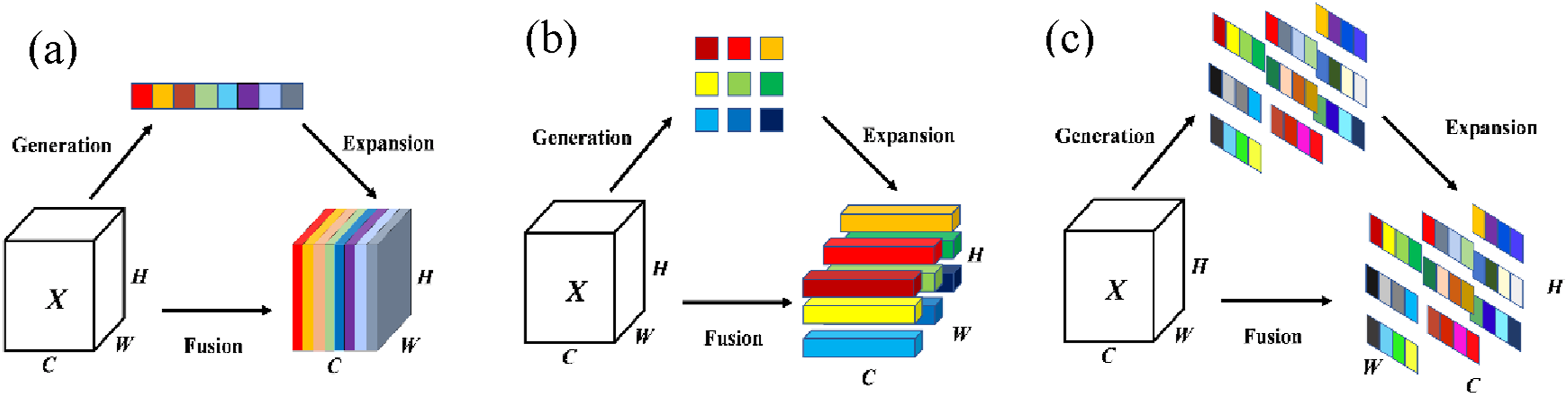
Compared with traditional attention mechanisms, SimAM offers three technical advantages for drone-based small-target detection. Firstly, the formulation of SimAM avoids adding extra convolutional layers or learnable parameters, which reduces the complexity and computational costs. Secondly, the unified 3D attention modeling of SimAM preserves the correlation of cross-dimensional attention, making SimAM capable of modeling interactions among effective features for low-contrast target detection. Thirdly, the global contextual evaluation of SimAM is sensitive to the fine-grained discriminative cues of the object of interest while suppressing the background noise. This is especially useful for distinguishing small padstone targets against complex and cluttered backgrounds.
Flatness measurement of bearing padstone
Hardware development
A prism optical target is integrated into the drone platform for rapid flatness measurement of bearing padstones, as illustrated in Figure 6. The developed system comprises quadrotor drone platform, optical reflection target, camera system, on-board computing system, and a remote control system. Developed airborne system for flatness measurement (a) schematic diagram; (b) prototype.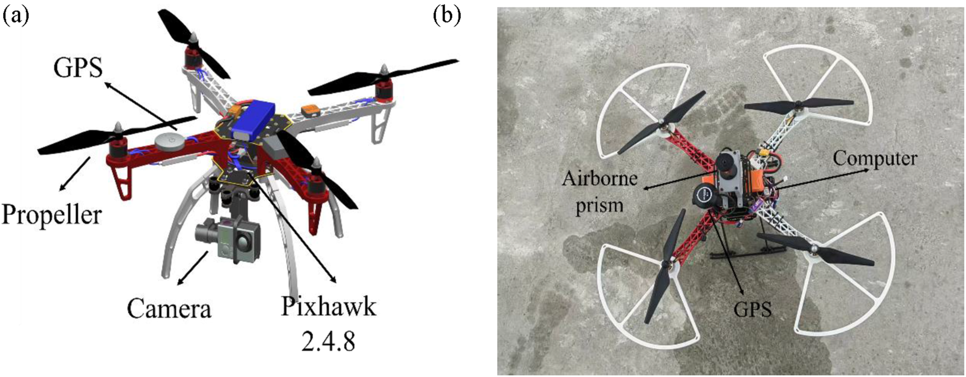
The drone platform used in this study is a custom-made system based on the DJI F450 quadrotor drone with a carbon fiber airframe, foldable landing gear and modular payload mounting system. The platform has an empty weight of 300 g and a maximum take-off weight of 2.5 kg. Thus, it can carry an integrated sensing and computing equipment with a payload of 1.2 kg. The power system consists of a 200 g high-density lithium battery, brushless electronic speed controllers, brushless motors, and high-efficiency propellers. The performance parameters of this configuration, including the maximum hovering time of 35 mins, cruise speed, and operational range, have been designed to meet the requirements of bridge inspection tasks. The drone system's flight management component is a Pixhawk 2.4.8 flight controller, equipped with a gyroscope, accelerometer, angular velocity sensor, barometric altimeter, M10 N GPS module, electronic compass, and high-precision control circuit. The controller is capable of achieving a hovering accuracy of ±0.1 m in position and ±1° in attitude, and is responsible for real-time calculation and adjustment of flight parameters. The ground control system consists of a matching receiver and a 2.4 GHz spread spectrum remote controller. Control signals are transmitted by radio waves and converted into digital signals processed by the onboard flight controller.
The camera system, mounted on a 3-axis stabilized gimbal at the front of the drone platform, is equipped with a fixed-focus lens (focal length: 3.5 mm) with a 120° field of view. It captures high-definition video at a resolution of 1920 × 1080 pixels and a frame rate of 120 fps, enabling high-speed video capture and detailed imaging of small bearing padstones. The camera is connected to an on-board Raspberry Pi 4B computing unit (weight: 66 g), which processes video streams in real time to support vision navigation and target detection tasks. The 3-axis gimbal allows for angle adjustments to compensate for jitter during flight for stable imaging. To retain critical fine-grained details for small-target detection, the images are sent through a USB 3.0 interface in RAW format to the on-board Raspberry Pi 4B computer. The USB 3.0 interface is chosen due to its high bandwidth (5 Gbps) and low latency. Specifically, the calibrated per-frame transmission latency reaches approximately 8 ms. Combined with the pre-calibrated exposure time and white balance parameters, this results in continuous and stable image deliveries under sufficient daytime lighting conditions.
The prism target for the developed drone system is a Leica GRZ4 optical prism (weight: 87 g, prism constant: −30.4 mm, angular resolution: 0.01), which is attached on top of the drone using a 3D printed carbon fiber bracket to ensure stable optical signal transmission and auxiliary positioning.
The on-board computing system uses a Raspberry Pi 4B module to convert pixel coordinates to world coordinates using pre-calibrated camera intrinsic parameters and external parameters. This coordinate transformation constitutes an important step that can help to map the 2D image-based target to 3D world coordinates. The processed 3D target position information is then packaged into MAVLink message protocol format and transmitted to the Pixhawk 2.4.8 flight control system via a UART serial port with a baud rate of 57,600 bps. The latency when sent from the computer to the flight control is less than 5 ms. Only result samples with a confidence level greater than 0.7 are transmitted to ensure control accuracy. Each MAVLink message carries information including the target ID, 3D coordinates, and the confidence score, allowing the flight control system to rapidly identify valid targets and implement necessary navigation adjustments. The two interconnected data transmission links enable collaboration along the camera, on-board computing unit and flight control system with an end-to-end total latency of less than 25 ms.
A small drone platform with propeller guards is adopted to avoid propeller damage due to contact with padstone edges. A reflective target is mounted on the top of the drone platform. The front portion of the drone is equipped with an adjustable-angle camera module for image acquisition, while all propellers are fitted with a protective frame. This design lowers the risk of landing operations damaging the propeller with obstacles on bridge bearing.
The workflow for rapid flatness measurement of bearing padstones using the developed drone system is illustrated in Figure 7. In this system, the drone follows a flight trajectory that is programmed in advance. When a bearing padstone is detected in the camera view, the drone starts hovering and moves to the position using the 3D spatial coordinates of the target from the detection algorithm. When a single frame detects multiple bearing padstones, the landing control system of the developed drone system uses a target prioritization algorithm to select landing target. As the DCXG201 camera has as fixed resolution with 1920 × 1080 pixels, the image center is defined at pixel coordinate (960, 540). The drone system will automatically select the bearing padstone whose target center (in pixel coordinates) is closest to this coordinate. The flight control system adjusts its location incrementally until the target center aligns with the image center when landing the drone system. Workflow of the developed system for flatness measurement.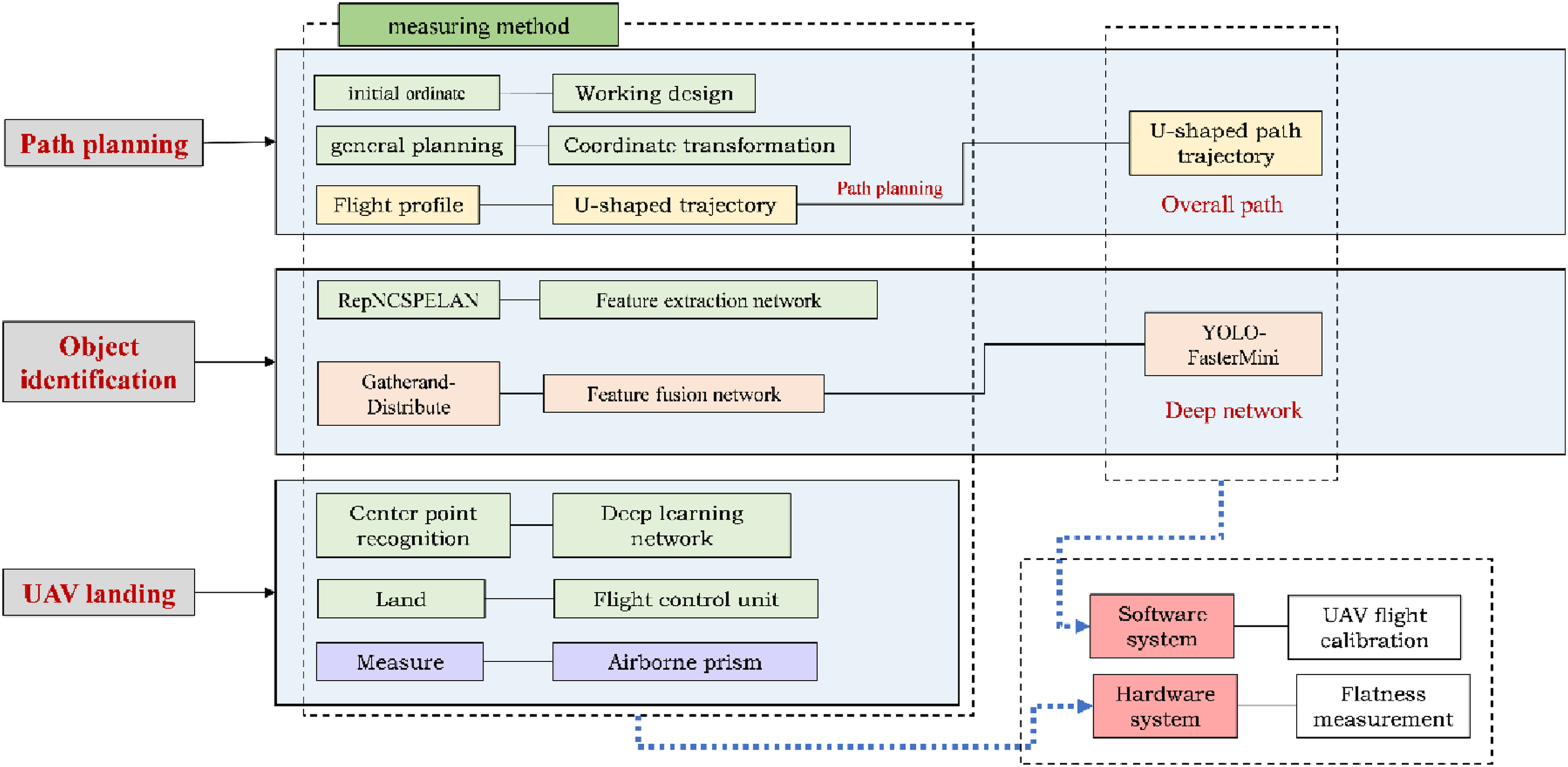
When vertically aligned over the target bearing padstone, the drone performs a controlled landing and descends down onto the padstone. To determine the flatness of the bearing padstone, a ground-based total station is used to measure the height of multiple points on the padstone. The drone climbs to its original cruising altitude and resumes to the preprogrammed flight route once the measurement sequence is completed. It is repeated 3 to 5 times for each padstone to ensure accuracy and reliability of measurements. In this way,the flatness measurements for all bearing padstones on one bridge pier can be measured. Then, the drone navigates to the adjacent pier and repeats the entire workflow, enabling efficient flatness measurement of bearing padstones across the entire bridge structures.
The drone system builds its core path planning strategy based on rough coordinate data. The initial flight path is generated solely using approximate coordinates of bridge piers and bearing padstones given by the design team. The objective of this pre-planning stage is to generate an initial path for the developed drone system to bypass non-inspection areas that includes complex terrain and overhead power lines, to directly navigate to the general area of target bearing padstone.
Bearing flatness calculation
The principle of bearing flatness extraction for bridges is shown in Figure 8. The schematic diagram presents a representative case where each bridge pier consists of two rows of padstones in each bridge pier. Although this arrangement is used as an example for clarity, the proposed method can be applied to different types of bridges. Schematic diagram of bearing flatness calculation (a) horizontal relative elevation; (b) longitudinal relative elevation.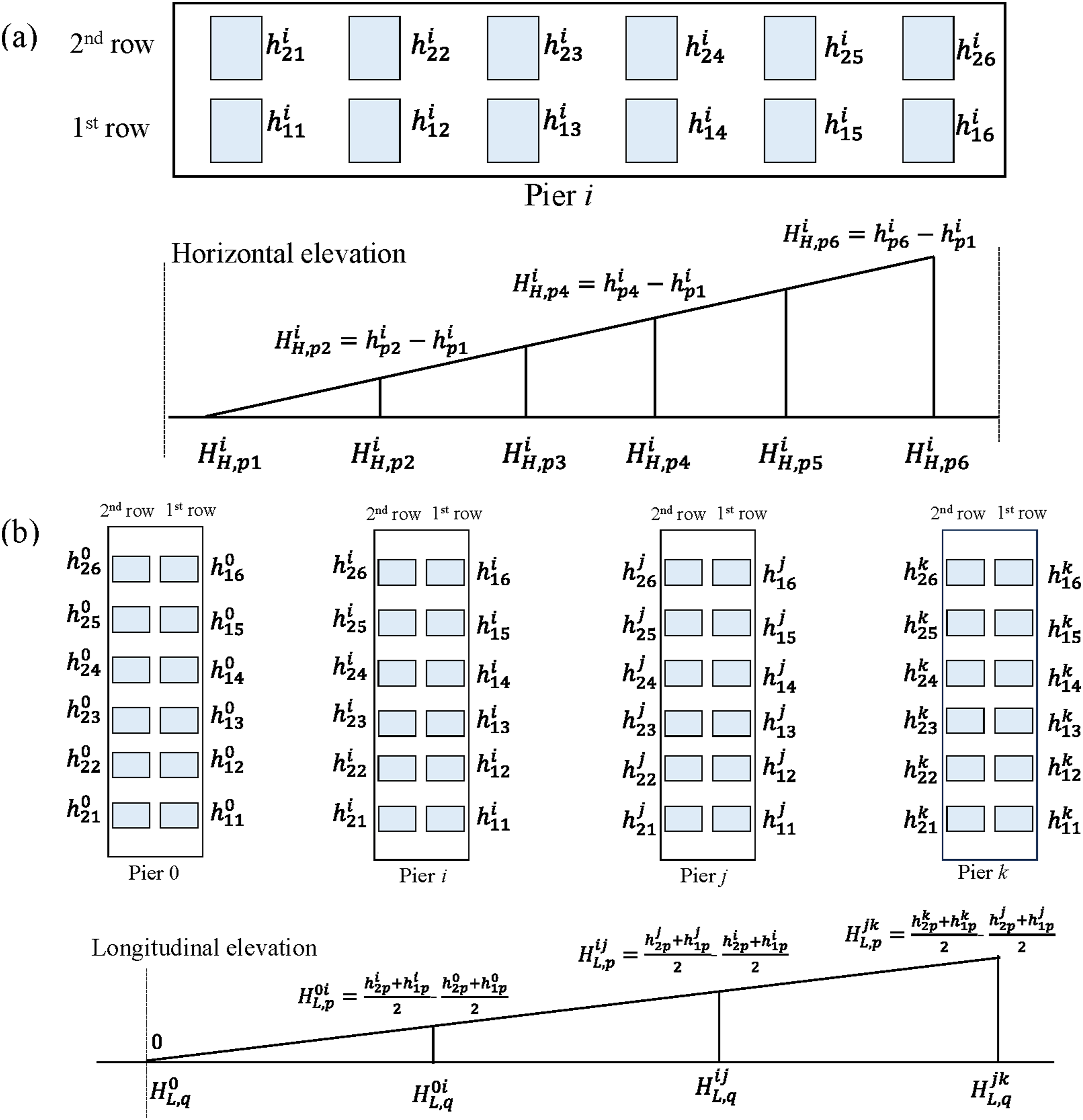
In this example, the problem is simplified by focusing on a 12 padstones bridge pier, where the drone is required to traverse all padstones without repetition and minimize the total flight distance. This study employs both an exhaustive method and a particle swarm optimization algorithm for the path planning. All possible sequences of the remaining 11 points are calcualted starting from the initial position. For each sequence, the path length from the starting point, through all padstones in the sequence, and back to the starting point is calculated. The results of these calculations lead to the determination of a ‘U’-shaped flight path.
As shown in Figure 8, taking Pier i as an example, the relative height

The method for calculating the longitudinal height difference of the padstone is analogous to the method used for determining the horizontal relative elevation. This process entails averaging the height of the padstone, as identified by the same number, across the two rows of each pier to ascertain the relative height at its position. The relative elevation of the padstone in the longitudinal direction is then computed as follows:
Dataset construction and model training
Dataset construction
This section provides details on a dataset development for the classidication of bearing padstones. The dataset was developed for a binary classification task where each image is labeled with a single padstone type. The data acquisition was conducted using a DJI Mavic 3E drone with a 48MP camera. To achieve complete coverage of the target inspection area, a customized flight path was created based on high-resolution mapping data to cover the entire region of interest. The primary dataset was collected from real-world engineering projects. During data collection, the drone operated at an altitude of 120 m above sea level with a total cruise of 15 minutes. The on-board camera recorded video footage of the bearing padstones and still frames were extracted from this video to compile a final dataset. The data diversity was enhanced by using two different imaging angles: a 45° forward-tilt angle and 90° vertically downward nadir angle. Model generalization and false detection rates are ensured using various data augmentation techniques through rotation, scaling, brightness adjustment, and Gaussian noise addition. Additionally, images of construction sites without bearing padstones were collected as negative samples. The developed multi-angle bearing padstone dataset (10,172 images) is shown in Figure 9. These images were randomly separated into training, validation, and test sets at an 8:1:1 ratio. The training set comprises of 8382 samples, the validation set includes 912 samples and the test set is 890 samples. Constructed dataset for bearing padstones.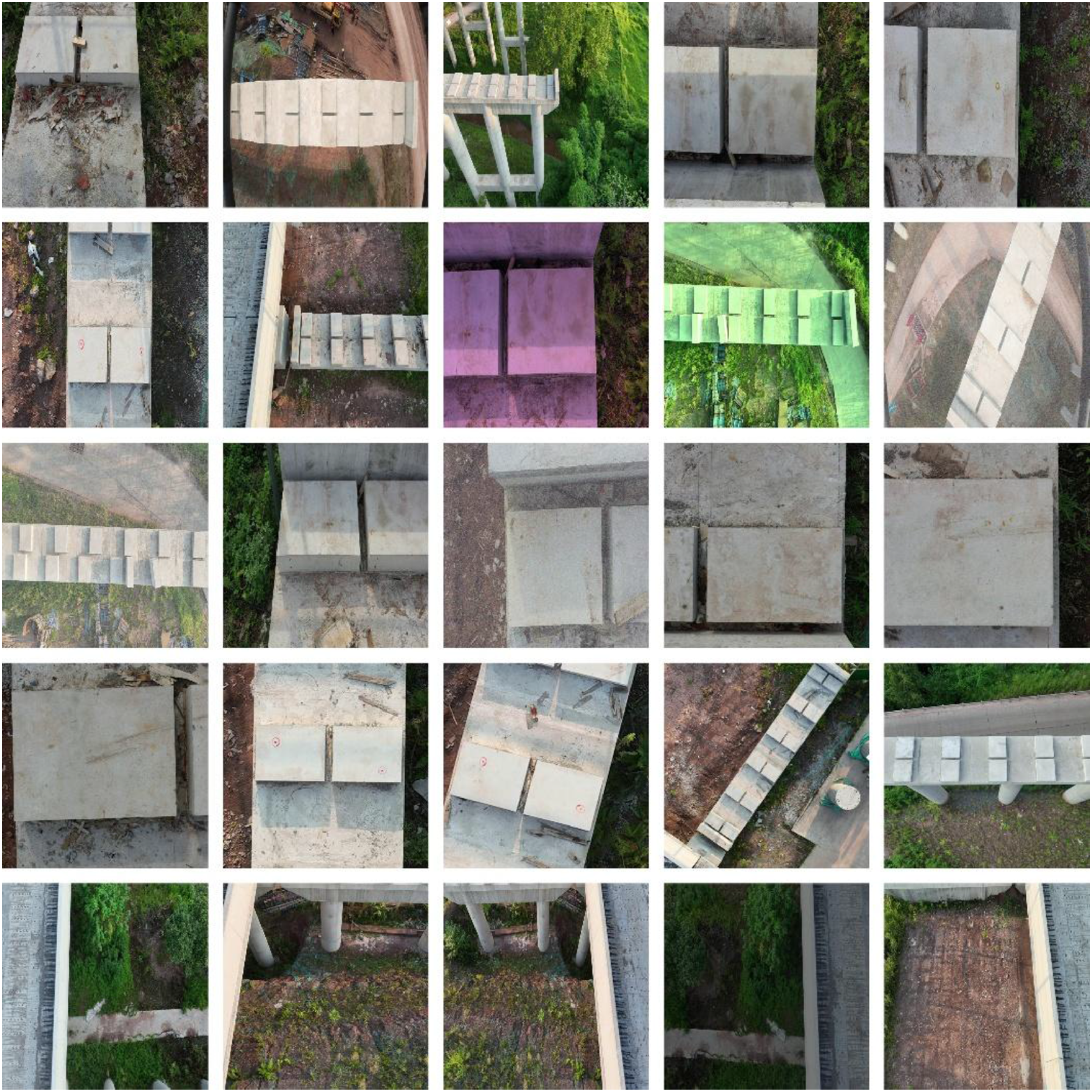
Model training
The developed lightweight network in this paper is implemented using the Python 3.10 and the Pytorch 2.0.0 framework. The model training is executed on a cloud server with RTX4090 GPU (24 GB of video memory) and CUDA 11.8. To evaluate the training performance and defect detection capability of the developed model, mean Average Precision (mAP), number of model parameters (Params), number of floating-point operations (GFLOPs), and frame rate (FPS) are considered. These metrics collectively evaluate the model’s performance and real-time processing capabilities.
The mAP value indicates the average precision across all categories and is represented in the P-R graph as the area under the curve. The calculation formula is expressed as:
Precision (P) refers to the ratio of correctly identified positive samples to all identified positive samples. It is the the proportion of true positive samples in all identified samples. The mathematical formula is expressed as:

Recall (R) measures the ability of test to give positive result when the sample is positive, which is calculated as:

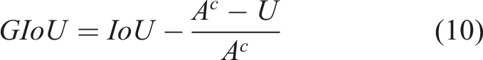
The term Params refers to the total parameters in network architecture measured in millions (M), and denotes the model’s storage space requirements. GFLOPs refers to the total number of floating-point operations performed by the entire network during inference. FPS stands for frames per second, typically indicates the number of frames processed every second. The GIOU loss is employed in the loss function:
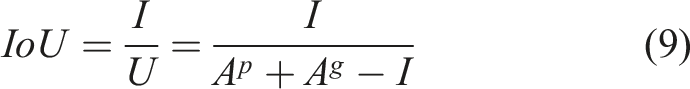
To examine the detection accuracy and speed of the developed model, five different models are chosen for comparison. The dataset described in Section 4.1 was used to train all models, with the hyperparameter set for all models trained at 300 epochs. The accuracy curve of the mAP@50 throughout the training process is illustrated in Figure 10. The mAP@50 score is the mean Average Precision when the Intersection over Union (IoU) threshold is equal to 0.5. The curve shows a gradual convergence around 220 epochs with no sign of overfitting. Training curves (a) precision training curve; (b) recall training curve; (c) mAP@50 training curve; (d) convergence curve of loss function.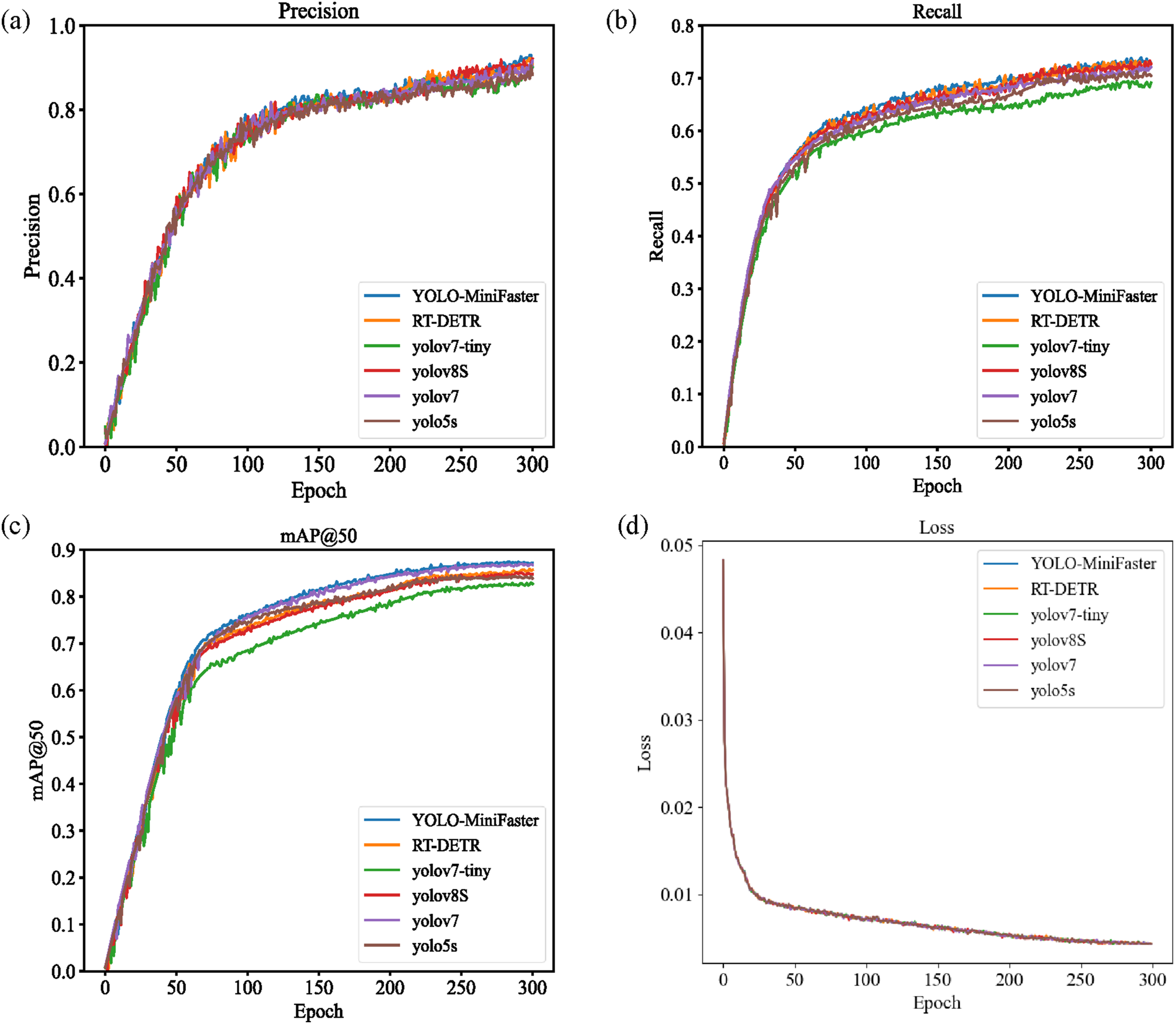
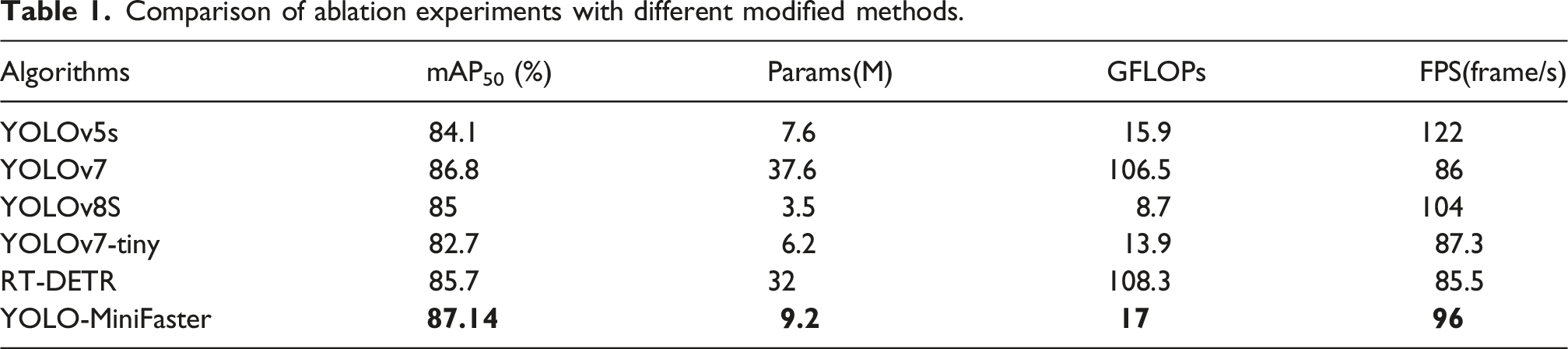
Comparison of ablation experiments with different modified methods.
Ablation study
The developed lightweight model is constructed of the RepCELAN structure, modified Slim-FPN feature fusion network, and the SimAM attention mechanism. To systematically evaluate the individual and combined effects of these components on small-target detection accuracy, model lightweight performance, and computational efficiency for multi-type bearing padstone detection, four model variants with different component combinations were designed. All variants were trained with the same bearing padstone dataset. Consistent hyperparameters were used for the entire training process to ensure a fair training comparison. The loss function convergence curves and average precision curves that were obtained during the training phase are shown in Figure 11. Training curves (a) mAP@50; (b) loss curve.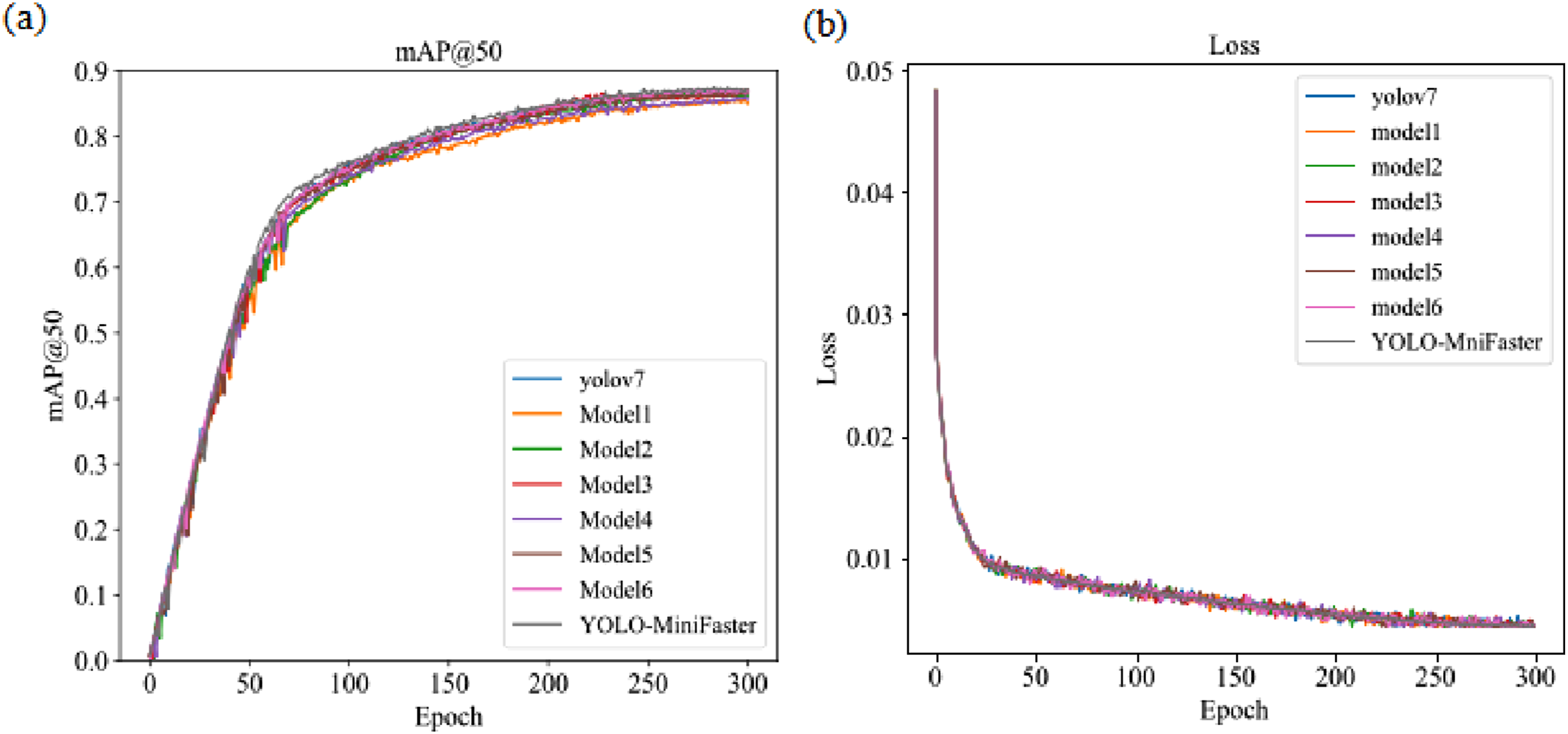
Comparison of ablation experiments with different modified methods.
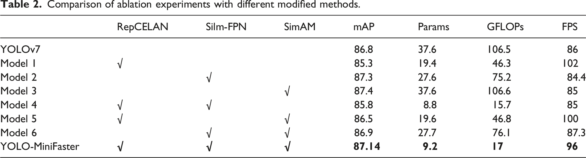
In comparison, the hybrid model variants (Models 4, 5, and 6) combine two modified components each. Model 4 integrates the RepCELAN backbone and Slim-FPN module, resulting in a 0.6% decrease in mAP with a 76.5% reduction in parameters and an 85% reduction in computational load. Model 5 combines the RepCELAN backbone and SimAM attention mechanism, yielding a 0.3% decrease in mAP alongside a 47.8% reduction in parameters and a 56.2% reduction in computational complexity. The proposed YOLO-MiniFaster model integrates all three modified components. This configuration achieves a 75.5% reduction in parameter count and an 84% reduction in computational time, while improving mAP by 0.37% relative to the baseline YOLOv7 model.
Field tests
Bridge description and field tests
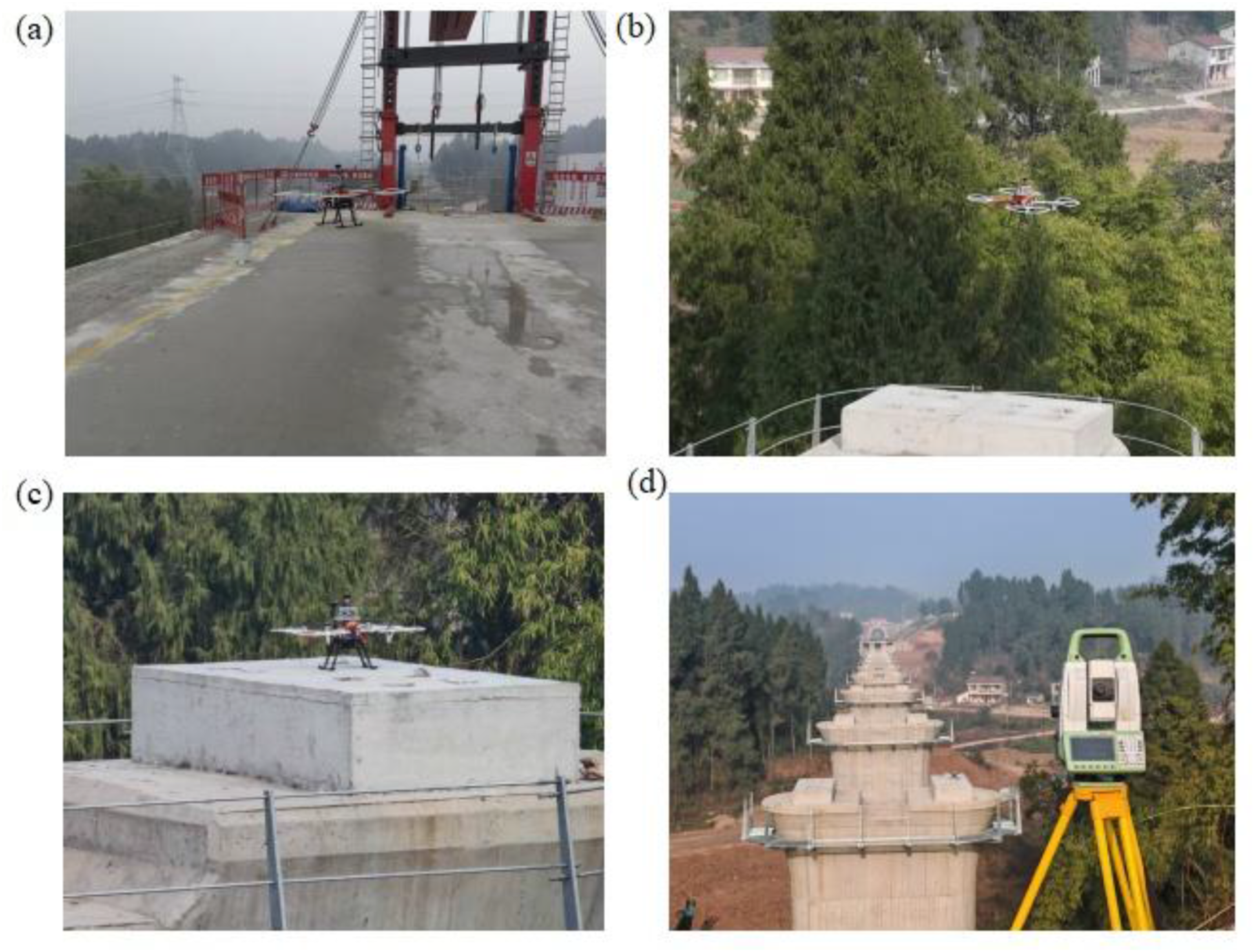
To further validate the robustness of the proposed inspection method, field tests were conducted on high-speed railway bridges in China. The expressway main line spans 179 km and includes 86 bridges of various types, with a total bridge length of approximately 39.4 km, accounting for 22.0% of the total route length. The bridge projects incorporate diverse span configurations to adapt to the region’s complex terrain conditions. For this study, 20 bearing padstones from 10 distinct bridge spans were selected as test objects, distributed across nine separate piers (Figure 12). Field deployment photographs of the developed drone system are presented in Figure 13. During field testing, after the drone system accurately navigates to the target padstone, a total station is used to measure the relative height of the padstone. The performance of the developed drone-based system is then quantitatively compared with the results obtained from traditional manual measurement methods. Bridge overview (a) schematic diagram of the bridge pier; (b) tested bridges (viewpoint 1); (c) tested bridges (viewpoint 2) . Field testing procedures (a) drone takeoff; (b) drone hovering; (c) drone landing; (d) bearing flatness measurement.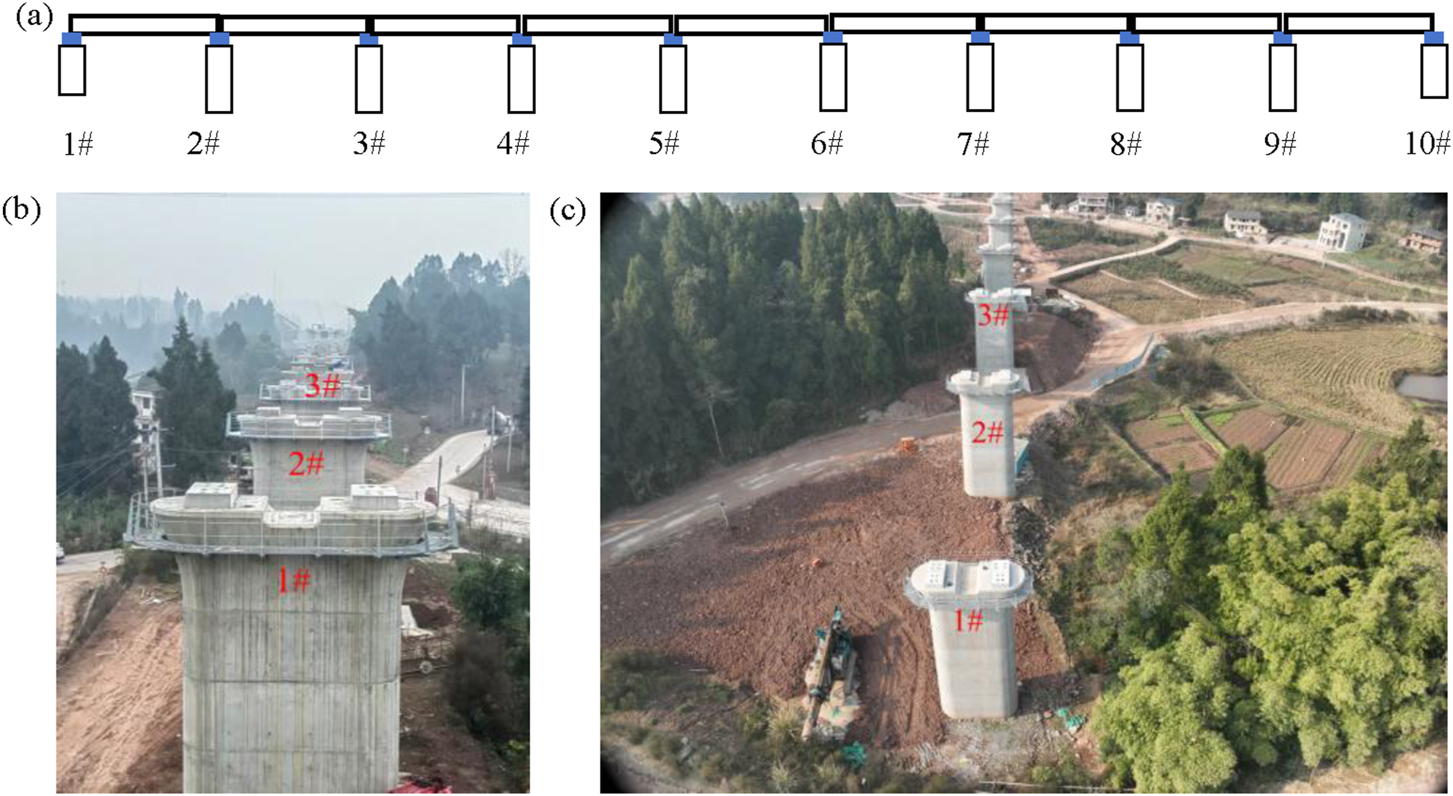
Measurement results
The drone follows a predetermined path and identifies the bearing padstone objects using the lightweight deep learning model. The recognition results are illustrated in Figure 14. Detection results of bearing padstones.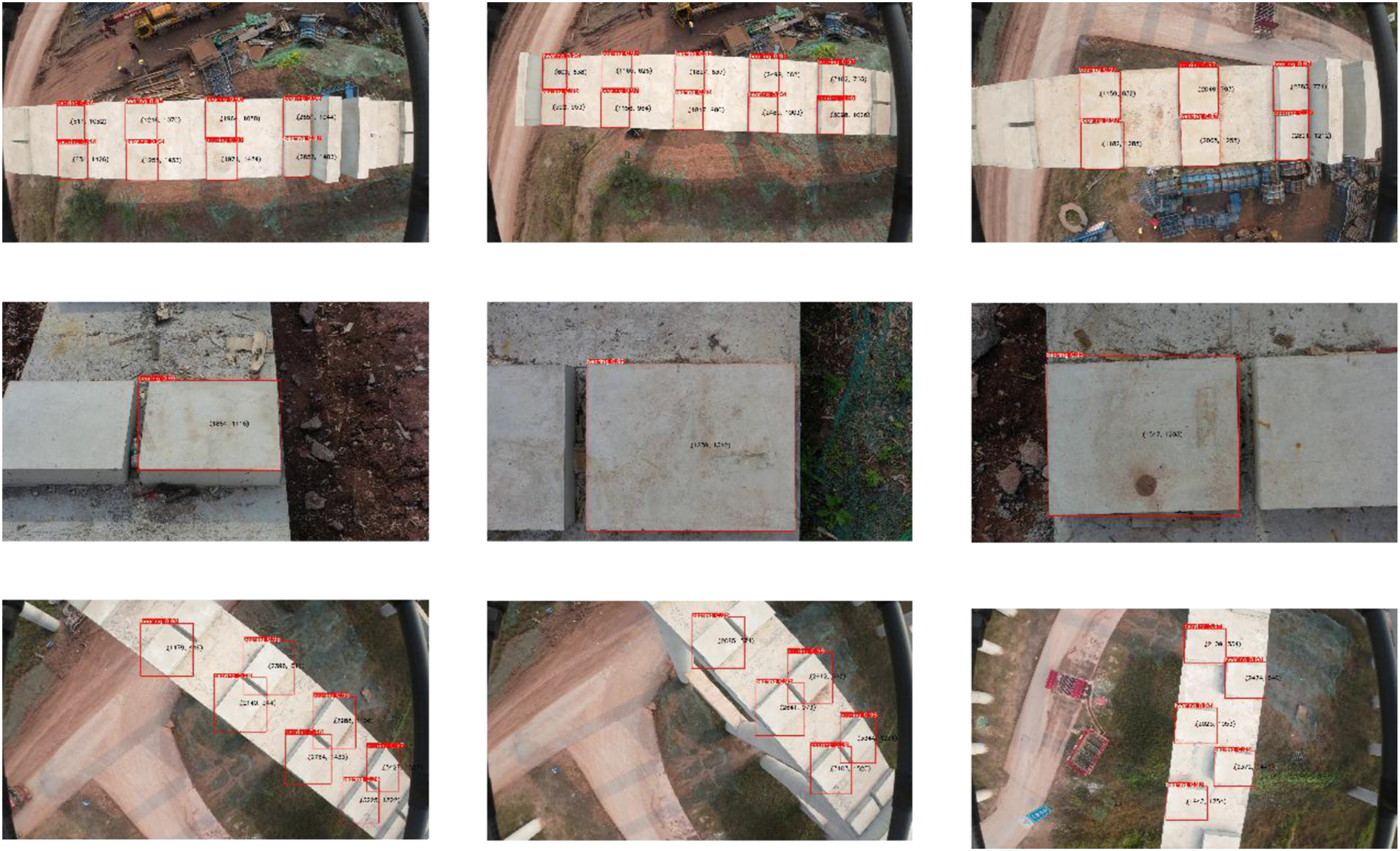
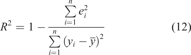
The accuracy of the measurement results was analyzed in terms of error by means of two parameters, the mean square error (equation (11)) and the coefficient of determination (equation (12)).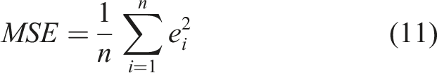
The absolute elevation of No. 1 padstone for Pier 1# measured using the drone system is equal to 356.229 m, whereas the traditional method of Pier 1# is 356.226 m, resulting in an error of 3 mm. The drone system recorded a measurement of 356.2347 m for No.2 padstone , while the conventional method obtained a measurement of 356.236 m, resulting in an error of 1.3 mm. The average absolute elevation measured by the drone system is 357.2506 m, while an average value of 357.253 m is measured by the traditional method, yielding an average error of 2.4 mm. The maximum height difference between the drone system and the prism is 1.1221 m, the minimum is 1.1150 m, and the average is 1.1189 m. In contrast, the traditional method has a maximum height difference of 0.9853 m, a minimum of 0.9758 m, and an average value of 0.9810 m, resulting in an average error of 14.05%.
In addition, error analysis was performed on the remaining 10 measurement points on each bearing. The calculation of MSE and coefficient of determination for left span was 8 × 10⁻⁵ and 0.99 respectively. The mean square error of the right span was 6 × 10⁻⁵ and its coefficient of determination was 0.99. A value closer to 1 signifies high accuracy. The coefficients of determination for the three groups of bridge pier is 0.99. This shows the developed method is highly accurate and comparable to traditional measurement methods.
As shown in Figure 15(a), the results from the two methods are almost the same, thus validating the effectiveness of the developed system for bearing flatness measurement. The longitudinal elevation differences of the padstone are taken with Pier 1# as a reference, as shown in Figure 15(b). As Pier 1# is used as the reference, thus it has the most absolute height among the piers in the test. The average longitudinal height difference measured by the traditional method is 0.408 m for the left span, while that of the developed drone system is 0.393 m with an average error of 3.6%. The traditional method recorded a measurement of 0.411 m for the right span, while the developed drone system measures 0.396 m with an average error of 3.6%. Comparison of flatness of bridge bearing padstone (a) absolute elevation(m); (b) relative elevation in longitudinal direction(m).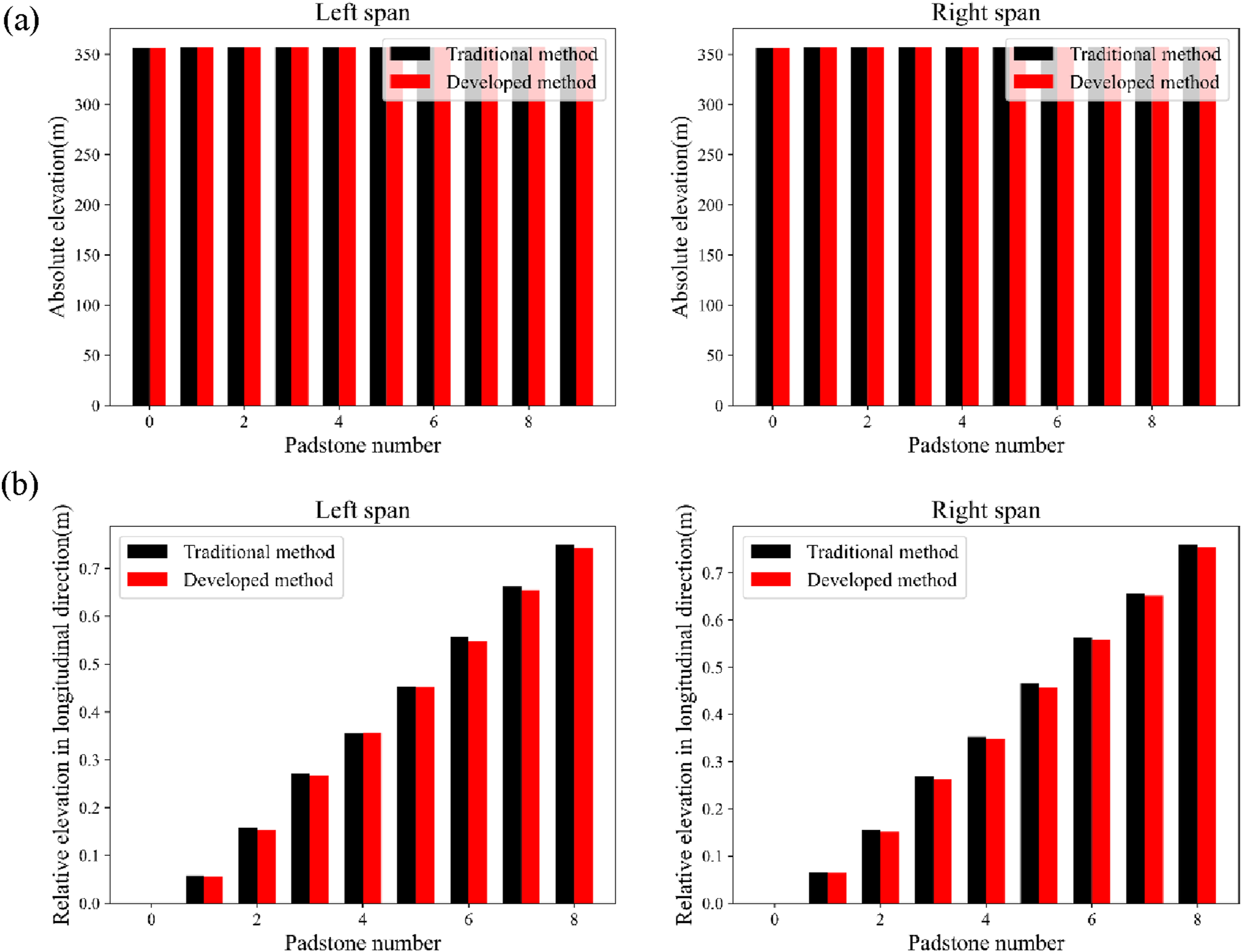
Longitudinal coordinate errors were analyzed at six measurement points, including the reference bearing padstone and the other bearing padstones, specifically left span and right span. For left span, the root mean square error was 6 × 10⁻⁵ with a coefficient of determination of 0.99, while the root mean square error was 5 × 10⁻⁵ with the same coefficient of determination of 0.99 for the right span. The coefficient of determination for the longitudinal elevation difference errors is approximately equal to the transverse elevation difference errors, indicating the high precision of developed drone system.
Comparison of measurement time of the developed system unit: s.
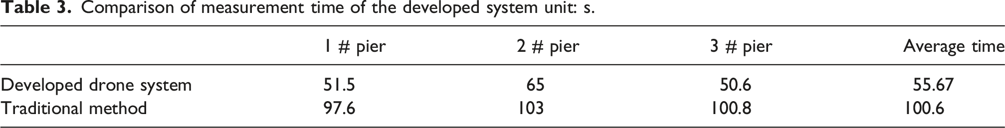
The measurement time for the three piers by using the developed drone system was 51.5 s, 65.0 s, and 50.6 s, respectively, giving an average of 55.67 s per pier. According to the results from the manual measurement method, the corresponding time consumption was 97.6 s, 103.0 s, and 100.8 s with an average time of 100.6 s per pier. A quantitative analysis shows that the measurement time for a single pier by the developed drone system is 45% higher than that of the traditional method, excluding the inter-pier transfer time.
When it comes to inter-pier transfer operations, the developed drone system can carry out transfer between piers in 10 s due to its high maneuverability. By contrast, manual measurements require site conversion with auxiliary equipment such as scaffolding and climbing ladders, which is cumbersome and dangerous for workers to perform this task. For this reason, the statistical comparison did not include inter-pier transfer time for the manual method. Without considering the time saved from inter-pier transfer, the developed drone system is still more efficient than using the traditional method.
Conclusions
Accurate measurement of bearing padstones flatness is crucial for ensuring the construction quality and operational safety of bridges. Conventional measurement methods, relying on total stations, inspection vehicles, and manual operations by skilled technicians, have limitations of high costs, safety-risk prone processes, and low efficiency in mountainous regions. In contrast, an drone system offers superior efficiency and operational safety while improving the measurement repeatability for bearing flatness. This study presents a rapid bearing flatness measurement system with a drone platform and lightweight object detection algorithm. The key findings are summarized as follows: (1) A lightweight deep learning model was developed for the identification of bearing padstones. That is achieved by integrating the RepCELAN feature extraction network, Slim-FPN feature fusion network, and SimAM attention mechanism, the developed model achieves high-precision and real-time detection of bearing padstones during flight operations. Training results achieved an average accuracy of 87.14%, with the model parameter count reduced to 75.5% of the original model. (2) A drone-based hardware system for flatness measurement of bridge bearings was developed and validated through field tests. The utilization of GPS, gyroscope, high-resolution camera, and prism target enables the direct measurement of bearing flatness. This lightweight system can deal with complex construction site environments and improve efficiency as there is no need for human placement of targets. (3) Field tests of the developed drone system were conducted on a newly constructed bridge. According to comparative tests with conventional methods, the maximum measurement error is only 3.9 mm, verifying the measurement accuracy and reliability of the developed system. As revealed by the analysis of the error, the mean square error is approximately 5 × 10⁻⁵ and the coefficient of determination is 0.99 for bearing flatness measurement.
The existing drone system lacks an auxiliary lighting system and waterproof protection, future work will be focused on integrating onboard illumination modules and enhanced environmental protection features for hardware optimization. Moreover, the developed drone system mainly runs on a conventional GNSS-based navigation system, which limits its positioning accuracy. Future work will develop advanced positioning technologies such as Real-Time Kinematic (RTK) GNSS and lidar-camera fusion algorithm to improve position accuracy and overall system performance.
Footnotes
Funding
The authors disclosed receipt of the following financial support for the research, authorship, and/or publication of this article: This work was supported by the Chengdu Key Research and Development Support Plan (Grant No.:2024-YF09-00058-SN).
Declaration of conflicting interests
The authors declared no potential conflicts of interest with respect to the research, authorship, and/or publication of this article.