
Abstract
Ultra-high-performance concrete (UHPC) provides lightweight, durable solutions for thin-walled structures in marine environments; however, conventional prestressing introduces considerable challenges in construction and long-term durability. This study proposes a novel composite system using unprestressed steel strands as passive reinforcement, benefiting from the exceptional properties of UHPC to enable the full utilisation of the strand tensile strength without prestressing, thereby simplifying construction. To validate this concept, the flexural performance of six beams and eight slabs was evaluated under four-point bending to investigate the effects of steel fibre content and reinforcement ratio. The results indicate that steel fibre content is the primary determinant of performance at the serviceability limit states (SLS), whilst the reinforcement ratio governs the ultimate limit states (ULS). An increased steel fibre content significantly enhanced crack control, a critical factor for durability in corrosive marine environments. Although higher reinforcement ratios generally reduced material efficiency, over-reinforced members exhibited superior crack control. A near-linear relationship was observed between the reinforcement ratio and peak load; however, excessive reinforcement altered the failure mode from strand rupture to concrete crushing, thereby reducing deformation capacity. Finally, a deflection-based theoretical model was developed that accurately predicts the complete flexural response, with its predictions showing excellent agreement with the experimental observations.
Keywords
Introduction
The development of resilient and sustainable infrastructure for aggressive marine environments confronts significant material and constructional hurdles. Coastal and offshore structures, such as bridges and wind turbine towers, are relentlessly subjected to a combination of complex loading (e.g. waves and wind effects) and aggressive chemical exposure, leading to accelerated degradation of conventional reinforced concrete (RC) (Adedipe et al., 2016; Jimenez-Martinez, 2020; Wasim et al., 2020; Yi et al., 2020). The inherent vulnerabilities of RC, primarily the corrosion of steel reinforcement and the substantial self-weight of structural elements, compromise long-term serviceability and impose immense logistical and economic burdens during offshore construction (Sarker and Faiz, 2017). While structurally efficient for reducing self-weight, thin-walled designs exacerbate durability concerns and introduce construction complexities, particularly in marine applications where reduced concrete cover accelerates reinforcement corrosion. This challenge necessitates a shift towards advanced material systems capable of delivering enhanced durability and reduced weight, thereby extending structural lifespans and improving the economic viability of marine projects.
Ultra-high-performance concrete (UHPC) has emerged as a transformative material poised to address these challenges (Huang et al., 2022; Zhu et al., 2024, 2026). Characterised by its densely packed microstructure, UHPC exhibits compressive strengths exceeding 120 MPa and exceptionally low permeability, granting it remarkable resistance to chloride ingress and other forms of chemical degradation common in marine environments (Li et al., 2020; Shi et al., 2015; Wang et al., 2015). The incorporation of steel fibres imparts a distinctive pseudo-strain-hardening tensile behaviour, which promotes distributed micro-cracking and confers considerable ductility, a quality not typically associated with high-strength concretes (Bajaber and Hakeem, 2021; Du et al., 2021). These superior mechanical and durability properties (Ahlborn et al., 2011; Alkaysi et al., 2016; Huang et al., 2023; Li et al., 2020; Meng and Khayat, 2018; Yang et al., 2022; Zhu et al., 2020b) make UHPC an ideal candidate for creating slender, lightweight, and durable thin-walled structural components for marine applications (Song et al., 2020; Xue et al., 2020; Zeng et al., 2025). However, unlocking the full potential of UHPC in such applications requires a design approach that effectively manages cracking at the serviceability limit state (SLS) while ensuring sufficient strength and ductility at the ultimate limit state (ULS).
Traditionally, prestressing is employed to meet these demanding performance criteria. By inducing compressive stresses through tensioned steel tendons, prestressing enhances stiffness, controls cracking under service loads, and increases the ultimate load-bearing capacity by enabling the efficient use of high-strength steel strands (Gilbert, 2001; Nawy, 1996). Despite its established benefits, the application of prestressing to thin-walled UHPC members introduces a unique set of formidable difficulties (Deng et al., 2024b). The geometric constraints of slender sections complicate the placement of ducts and anchorages, while the high localised forces at anchorages can induce premature cracking within the UHPC matrix (He and Liu, 2011). Furthermore, the long-term durability of prestressed systems is highly contingent on grouting quality, which is notoriously sensitive to workmanship and can create pathways for corrosion if imperfectly executed, undermining the intrinsic durability of the UHPC itself (Chang et al., 2020; Li et al., 2011).
These limitations have spurred research into alternative reinforcement strategies, notably the use of unprestressed high-strength steel strands as passive reinforcement (Baran and Arsava, 2012; Budek et al., 2002; Ou et al., 2022a, 2022b; Wei et al., 2024). Steel strands offer high tensile strength and flexibility, making them suitable for placement within confined spaces and complex geometries (Baran and Arsava, 2012; Dang et al., 2014; Ding and Cao, 2024; Nawy, 1996; Ou et al., 2022a, 2022b; Xie et al., 2018). To improve crack control in such systems, recent studies have explored their integration with various fibre-reinforced concretes (FRCs) (Li et al., 2023, 2024; Tahenni et al., 2021; Yuan et al., 2020; Zhao et al., 2024; Zhu et al., 2025). For instance, Li et al. (2024) reported significant enhancements in the load capacity, ductility, and energy dissipation of shear walls containing both steel fibres and unprestressed strands. Yuan et al. (2020) demonstrated that, in RC beams strengthened with unprestressed strands, substituting conventional polymer mortar with ECC increased flexural capacity and effectively delayed crack propagation in tensile regions. Similarly, Zhu et al. (2021) observed that the incorporation of ECC improved both the flexural stiffness and deformation capacity of such members. In a separate study, Zhu et al. (2025) confirmed through bending tests on steel strand mesh-reinforced ECC two-way slabs that the benefits of ECC extend from strengthening applications to new construction. Zhao et al. (2024) investigated the compressive behaviour of steel strand mesh confined ECC columns, reporting significantly improved crack control, load-bearing capacity, and ductility relative to conventional RC columns. However, a critical gap remains, as conventional FRCs possess a relatively low compressive strength. This material mismatch prevents the full tensile capacity of the high-strength strands from being mobilised because the concrete crushes prematurely, which leads to an inefficient use of materials and limits the ultimate structural capacity (Li et al., 2023; Yuan et al., 2020).
This study therefore proposes a novel composite system for thin-walled structural members, combining unprestressed steel strands with UHPC. At the SLS, the steel strands and the bridging action of steel fibres are expected to control crack width and spacing. At the ULS, the exceptional compressive capacity of UHPC and the high tensile strength of the strands, coupled with the superior bond afforded by the dense UHPC microstructure (Zhan et al., 2024), should enable full mobilisation of the tensile capacity of strands and deliver enhanced structural performance. From a construction perspective, this structural form eliminates the need for prestressing operations, and the strands are sufficiently flexible to be placed within confined spaces and complex geometries. These attributes make the system highly suitable for the modular construction of precast thin-walled units for offshore applications. Given that the construction of marine structures is highly sensitive to transport, lifting, and scheduling (Sarker and Faiz, 2017), offshore wind turbine towers represent a pertinent application where the system is compatible with various precast tower designs (Barutha et al., 2019; Huang et al., 2025; Nahvi, 2017). Figure 1 illustrates the basic configurations of hexagonal and ring offshore wind towers that can be constructed using this system. Its lightweight and high-strength characteristics can reduce transport and lifting demands and shorten on-site installation times, thereby enhancing the economic viability of offshore renewable energy projects (Nahvi, 2017). Application concept: modular offshore wind towers constructed using thin-walled UHPC members with unprestressed steel strands.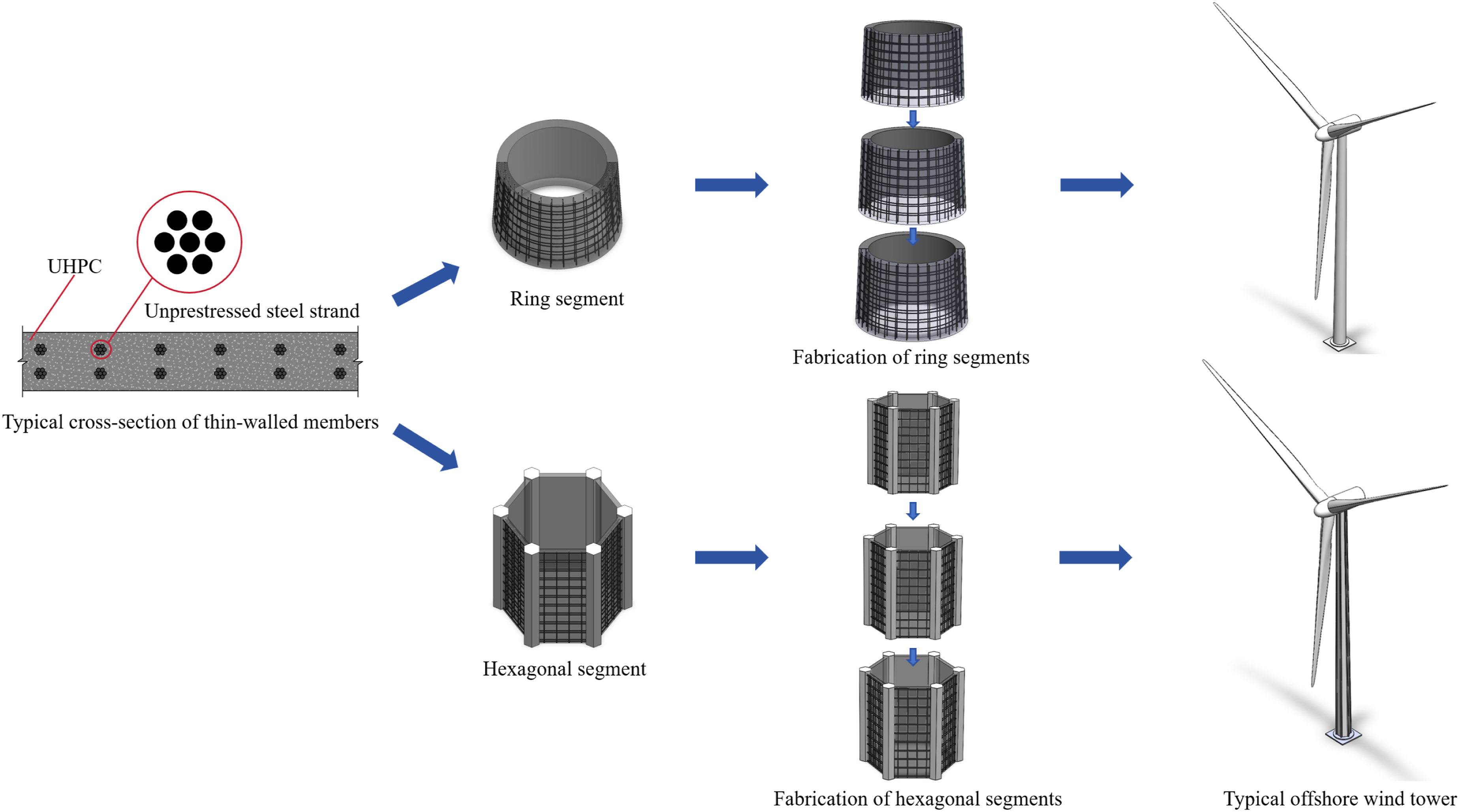
To the best knowledge of the authors, this structural concept has not previously been reported in the published literature. To validate this concept and establish a basis for structural design, this study presents a comprehensive experimental programme investigating the flexural performance of unprestressed steel-strand-reinforced UHPC beams and slabs. The investigation examines the effects of reinforcement ratio and steel fibre content on failure mechanisms, load-deflection response, flexural strength, deformation capacity, and crack control. In addition, a theoretical model based on deflection method was developed to predict the flexural response of these members.
Experimental programme
Specimen design and configuration
The experimental programme comprised six beams and eight slabs fabricated from UHPC reinforced with unprestressed longitudinal steel strands located in the tensile zone. The dimensions and reinforcement layouts for the beams and slabs are shown in Figure 2. As the shear capacity of UHPC is well-established as sufficient for slender members under flexural loading, no additional shear reinforcement was provided (Deng et al., 2024a; Huang and Yao, 2024; Li et al., 2015). Furthermore, compression reinforcement was intentionally excluded to prevent the potential for premature buckling or bulging of steel strands under compressive stresses, which could adversely affect the performance of the compression zone (Ou et al., 2022a). Dimensions of test specimens (unit: mm).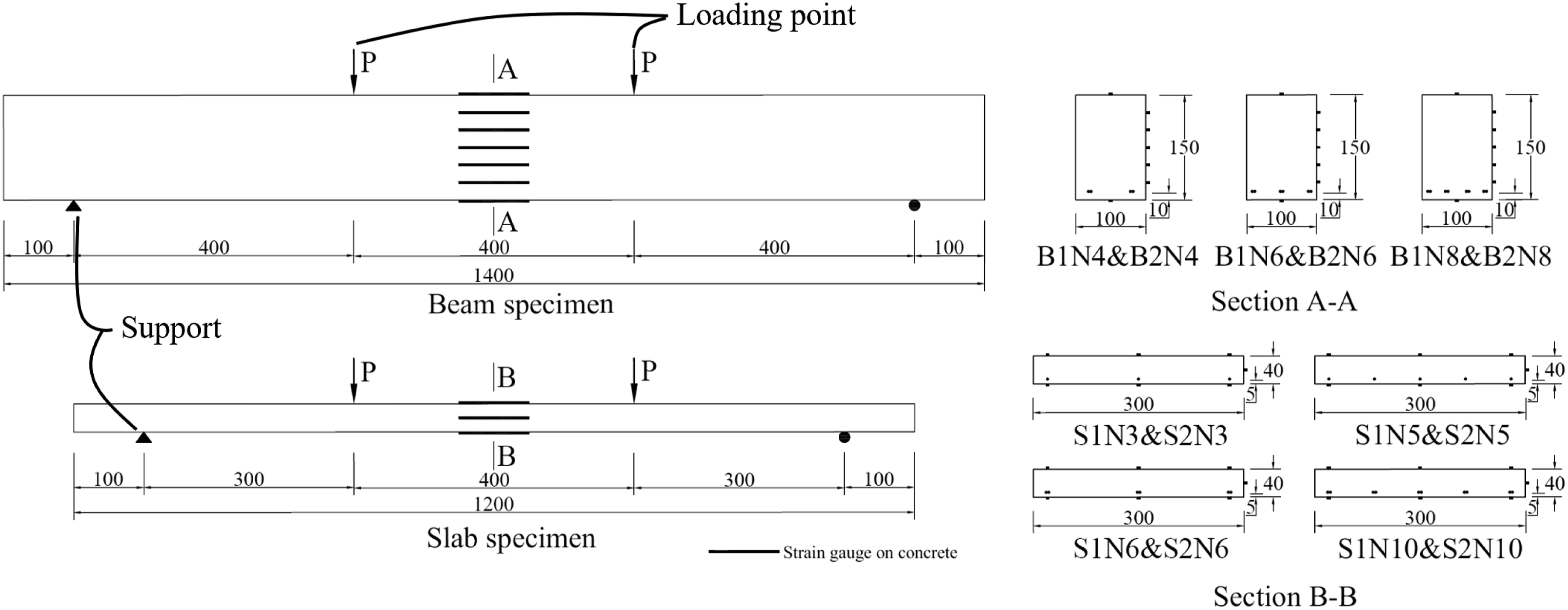
To ensure a flexure-dominated failure, the beams and slabs were designed with adequate shear capacity and comparatively weaker flexural resistance, having shear span-to-depth ratios exceeding 2.5 (i.e., 2.86 for beams and 11.43 for slabs). The beam specimens had a total length of 1400 mm, an effective span of 1200 mm, and a rectangular cross-section of 100 mm in width by 150 mm in depth. The slab specimens featured a total span of 1200 mm, an effective span of 1000 mm, and a rectangular cross-section of 300 mm in width and 40 mm in depth (Wu et al., 2024). The steel strands were arranged in a single layer near the bottom surface and distributed uniformly across the width of the specimen. The nominal concrete cover was 10 mm for the beams and 5 mm for the slabs. The strands were anchored by being threaded through drilled holes in the side of the casting mould and were subsequently secured with anchorage devices, as shown in Figure 3 (JGJ 337-2015, 2015). Reinforcement details of test specimens.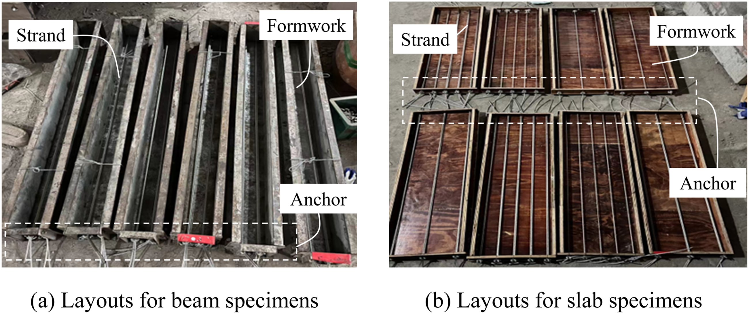
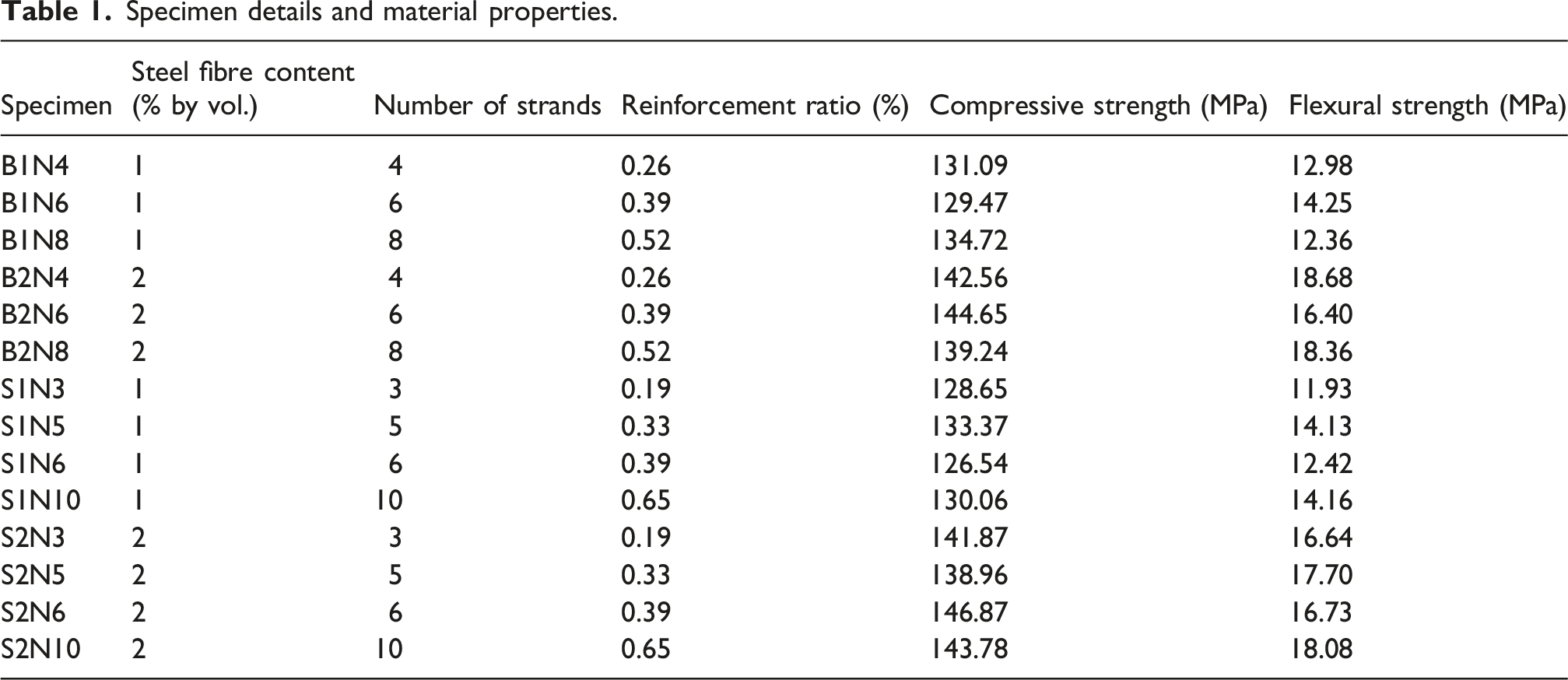
Specimen details and material properties.
Material properties
UHPC mix proportions.
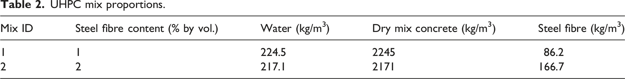
Due to batching constraints, specimens were individually cast, with one beam or slab produced at a time. To ensure consistency across batches, standardised mixing and casting procedures were rigorously followed, as detailed in Wu et al. (2024). For each batch, three 100 mm cubes and three 100 mm × 100 mm × 400 mm prisms were cast concurrently to determine the compressive and flexural strengths of the UHPC, respectively. Compressive and flexural strength tests were conducted on cubes and prisms, respectively, following GB/T 31387 (2015). Figure 4 illustrates typical failure modes observed during the compressive and flexural strength tests, while individual strength values are summarised in Table 1. Typical failure modes in UHPC material tests.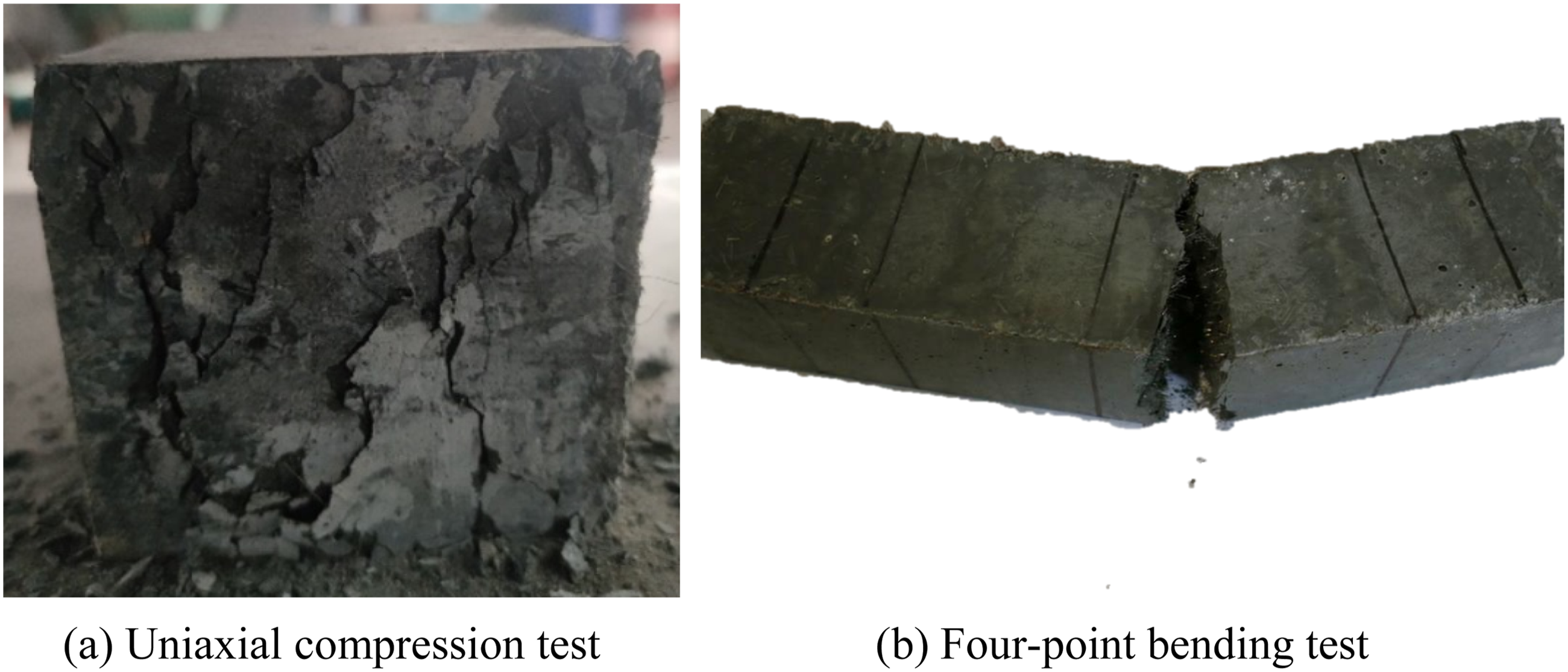
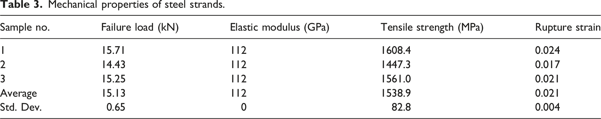
Mechanical properties of steel strands.
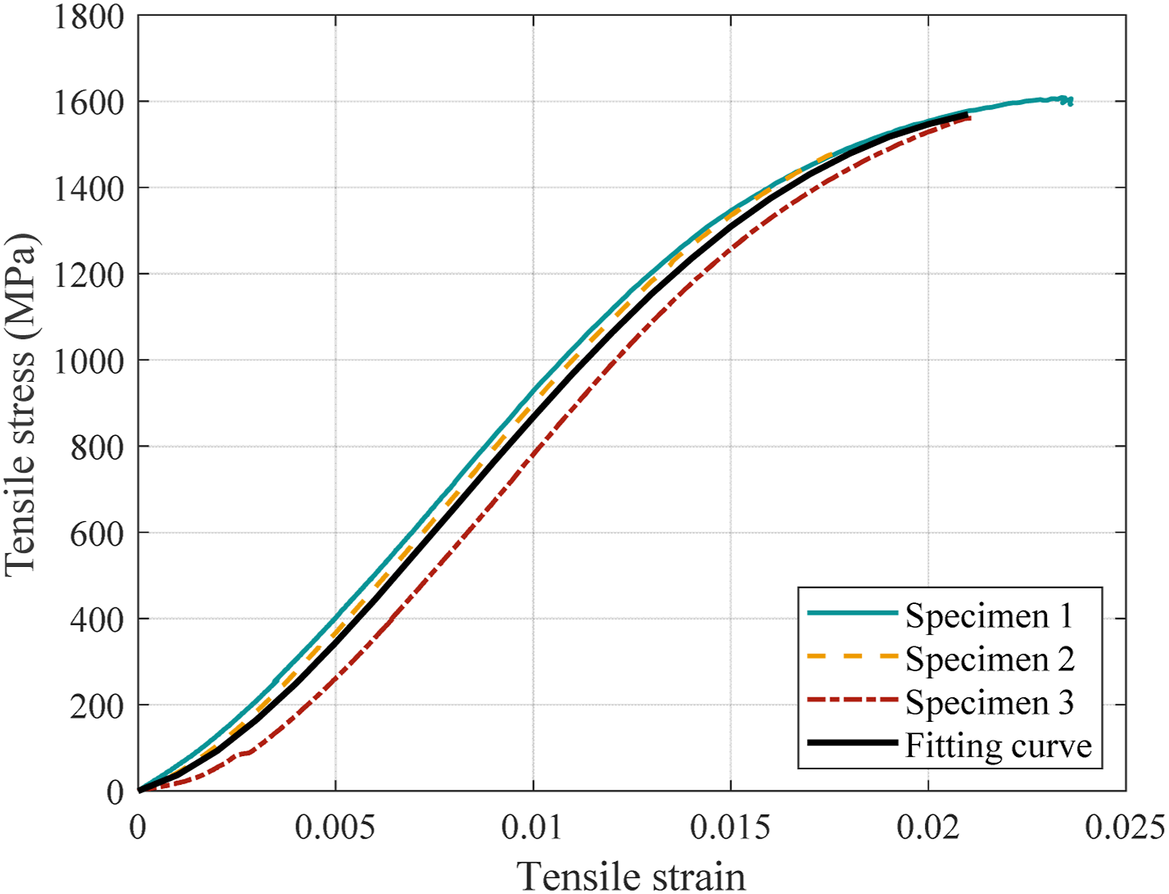
Stress–strain behaviour of steel strands.
Test setup and loading scheme
The four-point bending test setup is illustrated in Figure 6, using a beam specimen as an example. Each specimen was simply supported on steel pedestals, with one support pinned and the other a roller. The load was applied using a 1000 kN hydraulic jack through a steel spreader beam to two loading plates, positioned symmetrically about the mid-span at a 400 mm interval. Test setup for the four-point bending tests.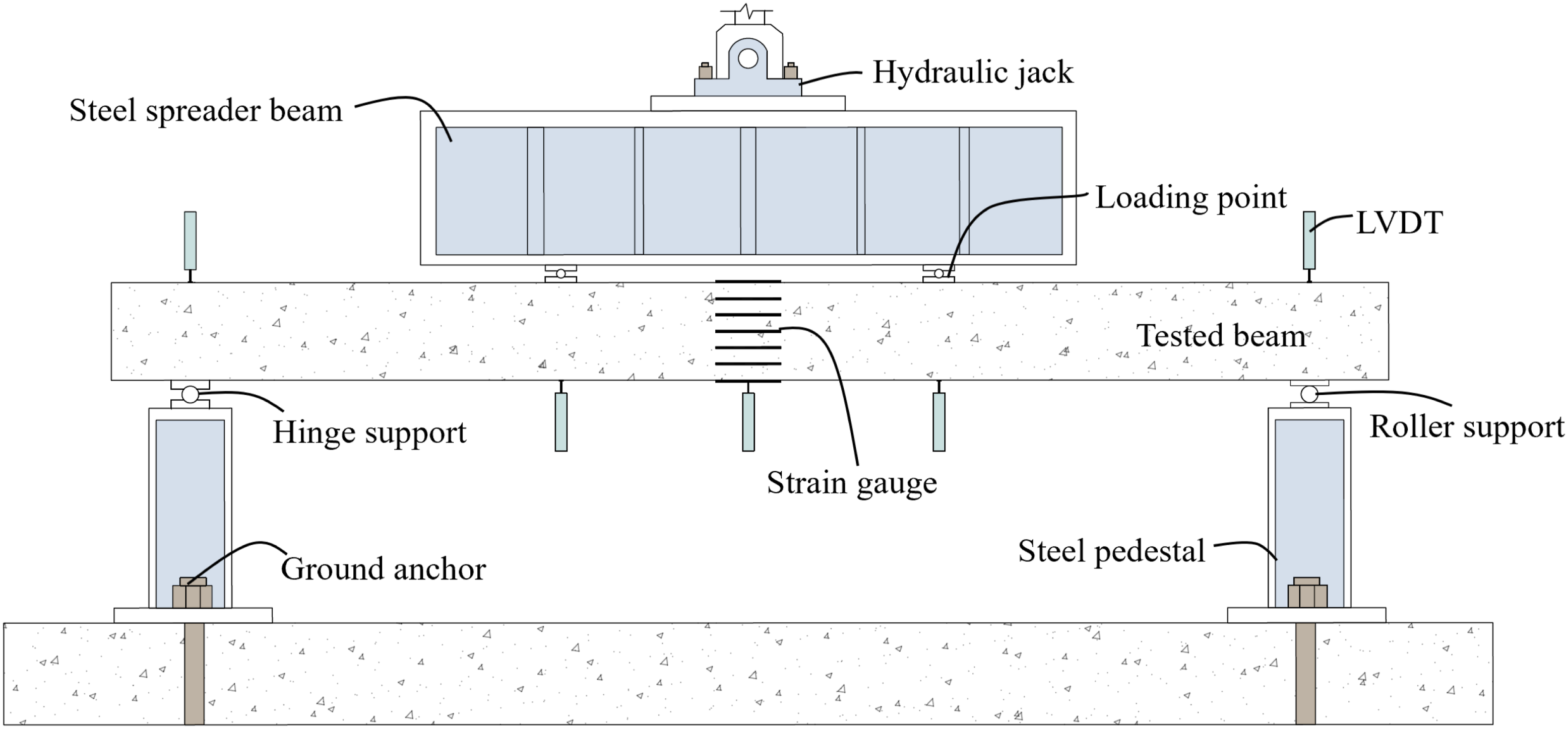
The vertical displacements at mid-span and two loading points were recorded using linear variable differential transformers (LVDTs), as illustrated in Figure 6. Two additional LVDTs were placed directly above the supports to measure any support settlement, which enabled the calculation of net deflection. Strain development and distribution at the mid-span were monitored using 100 mm strain gauges installed on the concrete surface. For beam specimens, seven strain gauges were used: one on the top face and one on the bottom, and five distributed vertically along one side, as detailed in Figure 2 (Section A-A). For slab specimens, eight strain gauges were employed: one at mid-height on each side face, and three spaced evenly across the width on both the top and bottom surfaces, as shown in Figure 2 (Section B-B) (Wu et al., 2024).
Crack widths were monitored using a crack-width microscope. Following preloading, all specimens were loaded monotonically under load control at a rate of 0.3–2.8 kN/min. During preloading, the maximum tensile strain at the mid-span was maintained below 100 µε to prevent concrete cracking, ensuring the specimen remained within its elastic range.
Results and discussion
Cracking behaviour and pattern
During loading, the first visible crack typically appeared on the bottom surface near the mid-span. As the load increased, microcracks formed and progressively propagated upwards towards the compression zone. This stable crack development was primarily due to the bridging action of steel fibres, which delayed crack localisation and improved crack stability (Feng et al., 2021). In the beam specimens, cracking progressed steadily, whereas the slab specimens, owing to their reduced thickness, exhibited more rapid and abrupt crack propagation. Nevertheless, both member types exhibited similar overall crack development patterns.
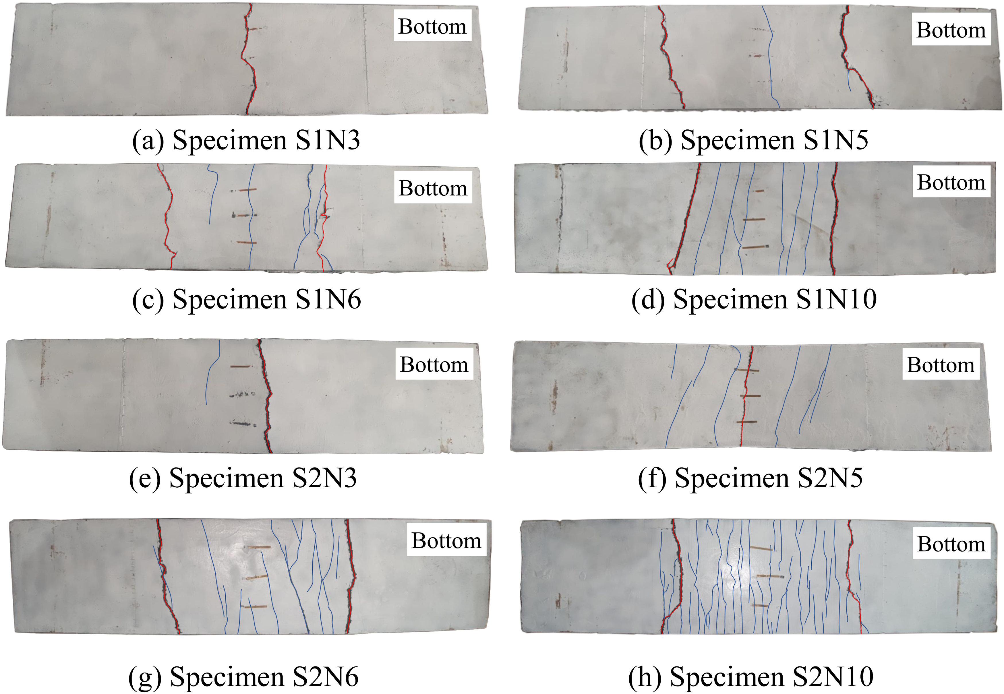
Figures 7 and 8 illustrate crack patterns of the beams and slabs after failure, with primary cracks indicated in red and secondary cracks in blue. The majority of cracks propagated vertically through the full section depth (red lines in Figure 7). The beam specimens typically developed a single dominant flexural crack, usually located at the mid-span or directly beneath loading points (red lines in Figure 7). The slab specimens, in contrast, exhibited two distinct dominant crack patterns: failure from a single crack at the mid-span [Figure 8(a), (e), (f)], or the development of two symmetrical cracks directly under the loading points [Figure 8(b)–(d), (g), (h)]. In addition to the main cracks, several secondary cracks were observed within the pure bending zone (blue lines in Figures 7 and 8). Generally, an increased reinforcement ratio resulted in a greater number of closely spaced microcracks, indicating enhanced stress redistribution and improved crack control, thereby inhibiting the formation of localised, wide cracks. Increasing steel fibre content from 1% to 2% slightly improved crack distribution, but this effect was considerably less significant than that of the reinforcement ratio. An analysis of crack width under service load is discussed further in Crack Width Development. Post-failure cracking patterns of beams. Post-failure cracking patterns of slabs.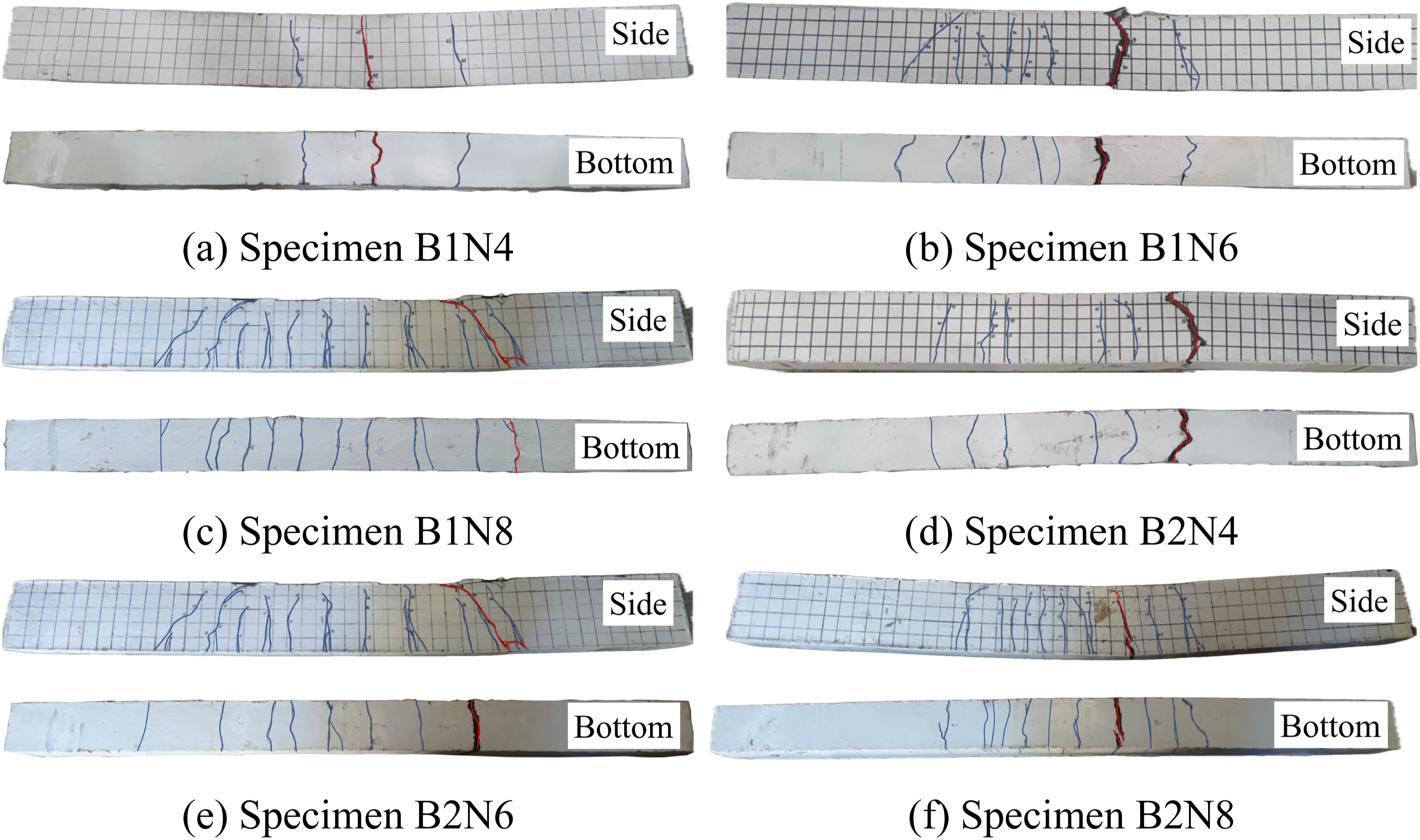
Failure mode
Summary of key test results.
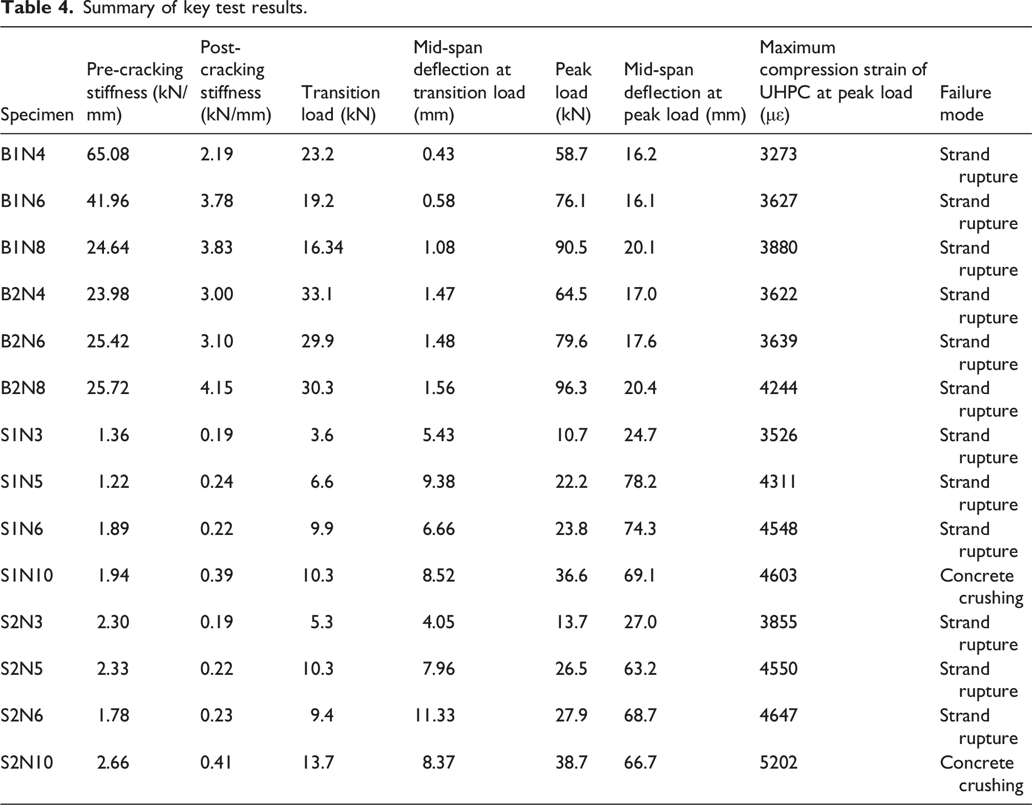
Two distinct failure modes were observed in the slab specimens. These were primarily governed by reinforcement ratio, as steel fibres mainly affect crack control rather than ultimate load capacity (Li et al., 2024; Wu et al., 2024). The specimens with the highest reinforcement ratios (i.e., S1N10 and S2N10) failed due to concrete crushing at the top compression fibre, exhibiting maximum compressive strains of 4603 με and 5202 με, respectively. The remaining slab specimens, which had lower reinforcement ratios, failed through strand rupture in a manner similar to the beam specimens.
Load-deflection behaviour
Figure 9 presents the load-deflection curves for all specimens, where deflection represents the net displacement at mid-span, and load is the sum of the two applied point loads. All specimens demonstrated bilinear behaviour, featuring a clear stiffness transition between the pre- and post-cracking stages. The secant stiffness values, defined as the ratio of peak load to corresponding deflection at each stage (Li et al., 2023), were computed and are summarised in Table 4. Load-deflection responses of tested members.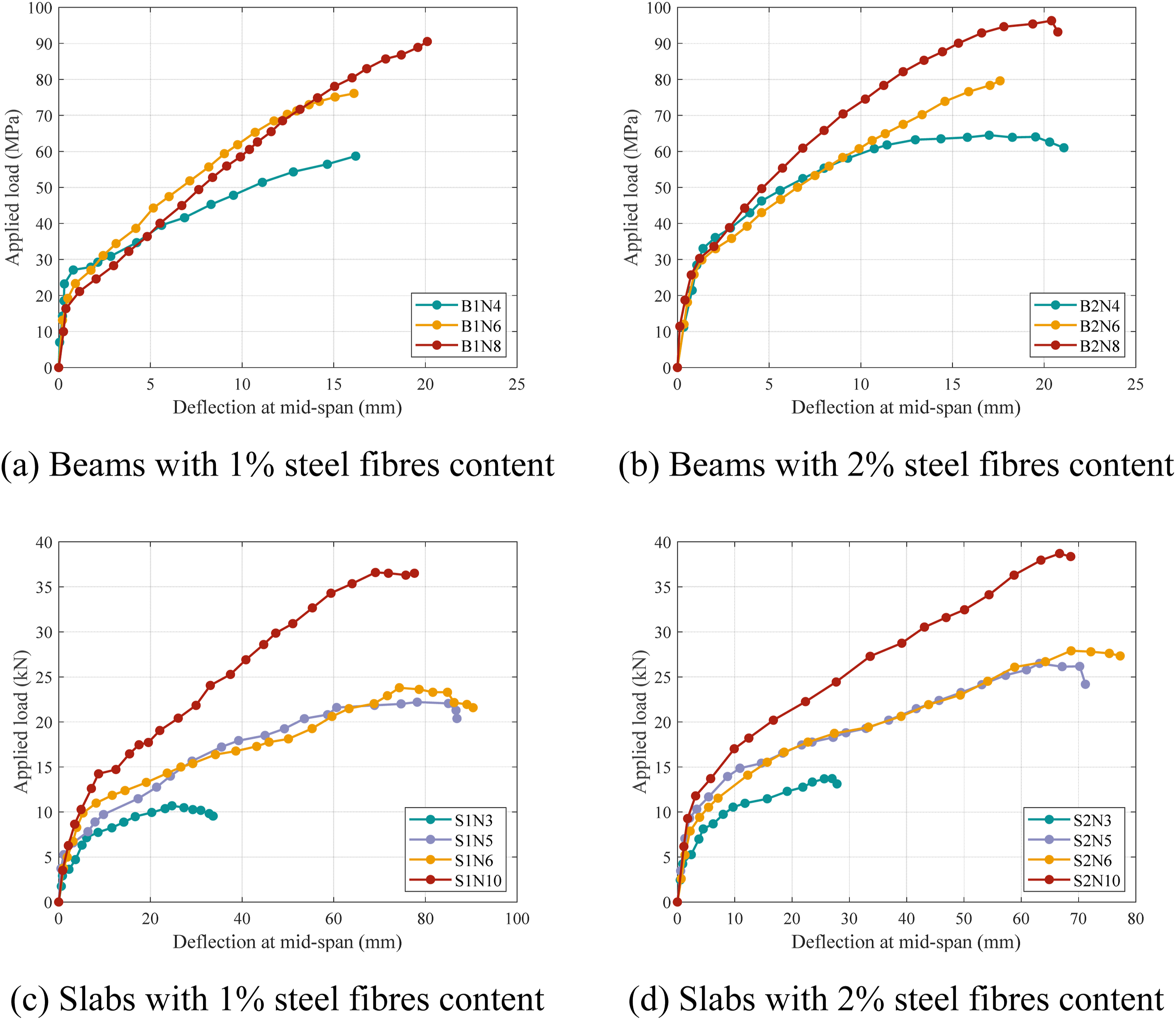
During the pre-cracking stage, all the specimens exhibited a near-linear elastic response with comparable stiffness within each member type. The average initial stiffness values were 35.1 kN/mm for the beams and 4.2 kN/mm for the slabs, indicating that pre-cracking stiffness predominantly depended on geometric characteristics and the properties of the concrete matrix, rather than on the reinforcement or steel fibre content.
Following cracking, the stiffness decreased significantly. The transition load, defined as the load at the end of the initial linear response phase, was similar across specimens with varying reinforcement ratios, indicating that the reinforcement had minimal influence at this stage. Increasing the steel fibre content significantly improved the transition load. For the beams, the transition load increased from 13.2 kN to 17.8 kN (a 34.9% increase) as steel fibre content rose from 1% to 2%; for the slabs, the increase was from 13.2 kN to 17.3 kN (a 31.4% increase). The similar improvements observed in both the beams and the slabs suggest that the effect of steel fibre content on the transition load of thin-walled UHPC members is largely independent of member size.
In the post-cracking phase, the stiffness increased with an increasing reinforcement ratio. For beams with 1% steel fibre content, the stiffness increased by 74.9% as the reinforcement ratio rose from 0.26% to 0.52%. In contrast, beams with 2% steel fibre content showed only a 38.3% stiffness increase, indicating that fibre bridging contributed more significantly to post-cracking stiffness in specimens with lower reinforcement ratios. In specimens with 1% steel fibre content, the limited availability of fibres led to reduced tensile resistance and rapid crack propagation, with the post-cracking stiffness being governed predominantly by the steel strands. Conversely, specimens with 2% steel fibre content exhibited stronger fibre bridging across cracks, which distributed tensile stresses more effectively, delayed crack opening, and thereby sustained a higher post-cracking stiffness even at relatively low reinforcement ratios. Thus, increasing reinforcement ratios yielded greater stiffness improvements in specimens with lower steel fibre content.
For slab specimens, stiffness improvements were modest (∼19.7%) when reinforcement ratio increased from 0.19% to 0.33% and 0.39%, but surged by 115.8% when further increased to 0.65%. Compared with beams, the effect of steel fibre content on the stiffness of the slabs was less pronounced. This difference may be attributed to the slenderness of the slabs, which leads to more severe sectional deformation at higher loads, resulting in fibre slippage or pull-out and consequently reducing the efficiency of the fibre bridging (Valentim, 2023).
The contribution of steel fibres to post-cracking stiffness was evident in all specimens, although variability in load-deflection behaviour was observed, especially for the beams. This variability can be attributed to the random orientation and non-uniform distribution of fibres during casting, which affects crack bridging efficiency. In thicker beam sections, an uneven fibre distribution caused by flow velocity gradients during casting may compromise uniformity, whereas the thinner sections of the slabs promote more uniform fibre dispersion and orientation (Yoo et al., 2016).
Load-carrying and deformation capacities
Figure 10(a) illustrates a near-linear correlation between the reinforcement ratio and the peak load for both beams and slabs. This linear correlation is attributed primarily to the fact that, within the range from under-reinforced to near-balanced reinforcement, the flexural strength at the critical section is predominantly governed by the reinforcement ratio, the tensile strength of the steel strands, the compressive strength of the concrete, and the internal lever arm (El-Helou and Graybeal, 2022; Zhu et al., 2025). As the mechanical properties of the steel strands and UHPC were consistent and variations in the internal lever arm were minimal (El-Helou and Graybeal, 2022; Zhu et al., 2025), the peak load exhibited an approximately linear relationship with the reinforcement ratio. Moreover, the exceptional compressive strength and superior bonding characteristics of the UHPC matrix facilitated effective stress transfer and uniform tensile stress distribution along the steel strands, which further supports the observed linear trend (Zhan et al., 2024). Relationship between reinforcement ratio and flexural capacity at the ULS.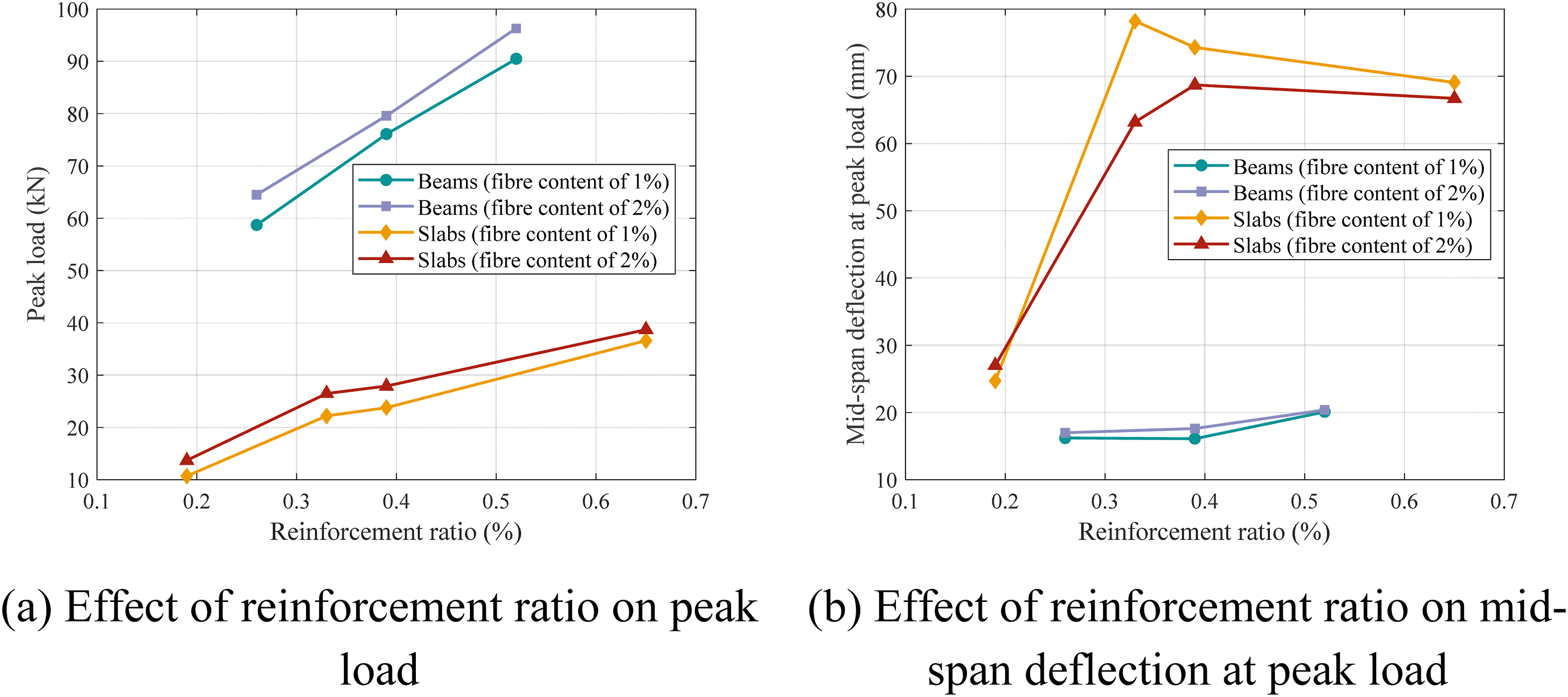
Figure 10(b) illustrates the relationship between reinforcement ratio and mid-span deflection at peak load. Although higher reinforcement ratios enhanced peak load, their contribution to deformation capacity was limited. The maximum deflections occurred at reinforcement ratios of 0.52% for beams (eight strands) and 0.39% for slabs (six strands). However, further increasing the reinforcement ratio to 0.65% in slab specimens notably decreased deformation capacity. This reduction corresponds to the transition in failure mode from strand rupture to concrete crushing. While a higher reinforcement ratio provides greater axial tensile stiffness that restrains crack opening at the SLS, it significantly increases the sectional flexural stiffness throughout the post-cracking stage. This causes a downward shift of the neutral axis, restricting the development of cross-sectional curvature before the UHPC reaches its ultimate compressive strain. Consequently, the member exhibits a stiffer overall response, and the excessive steel strands cannot fully mobilise their tensile capacity in an over-reinforced configuration. The premature concrete crushing mechanism fundamentally prevents the member from utilizing the ductility of the steel strands, leading to a profound reduction in the deformation capacity at the ULS.
The steel fibre content of UHPC significantly affected flexural performance at the ULS. Specimens with similar reinforcement ratios (e.g., S1N5 and S1N6) showed comparable behaviours, indicating that variations in UHPC properties may, in certain cases, overshadow the effects of reinforcement differences. Increasing steel fibre content from 1% to 2% improved the load-bearing capacity of beam specimens by up to 9.9%, with the greatest improvements occurring in specimens with the lowest reinforcement ratio (0.26%). Nevertheless, this enhancement did not significantly improve deformation capacity.
For slab specimens, increased steel fibre content also improved load-bearing capacity, although its effectiveness declined as reinforcement ratios increased. The improvements in load-bearing capacity decreased from 28.1% at a reinforcement ratio of 0.19% to only 5.7% at 0.65%. Furthermore, an increased steel fibre content generally resulted in a reduced deformation capacity. This effect is likely due to the relatively thin slab sections, which promotes more uniform fibre dispersion (Yoo et al., 2016). A higher steel fibre content more effectively suppresses crack initiation and propagation, resulting in higher transition loads (as indicated in Table 4) and consequently stiffer overall load-deflection responses (Figure 9). Thus, the ultimate state is achieved at lower deflections, thereby reducing the overall deformation capability.
Crack width development
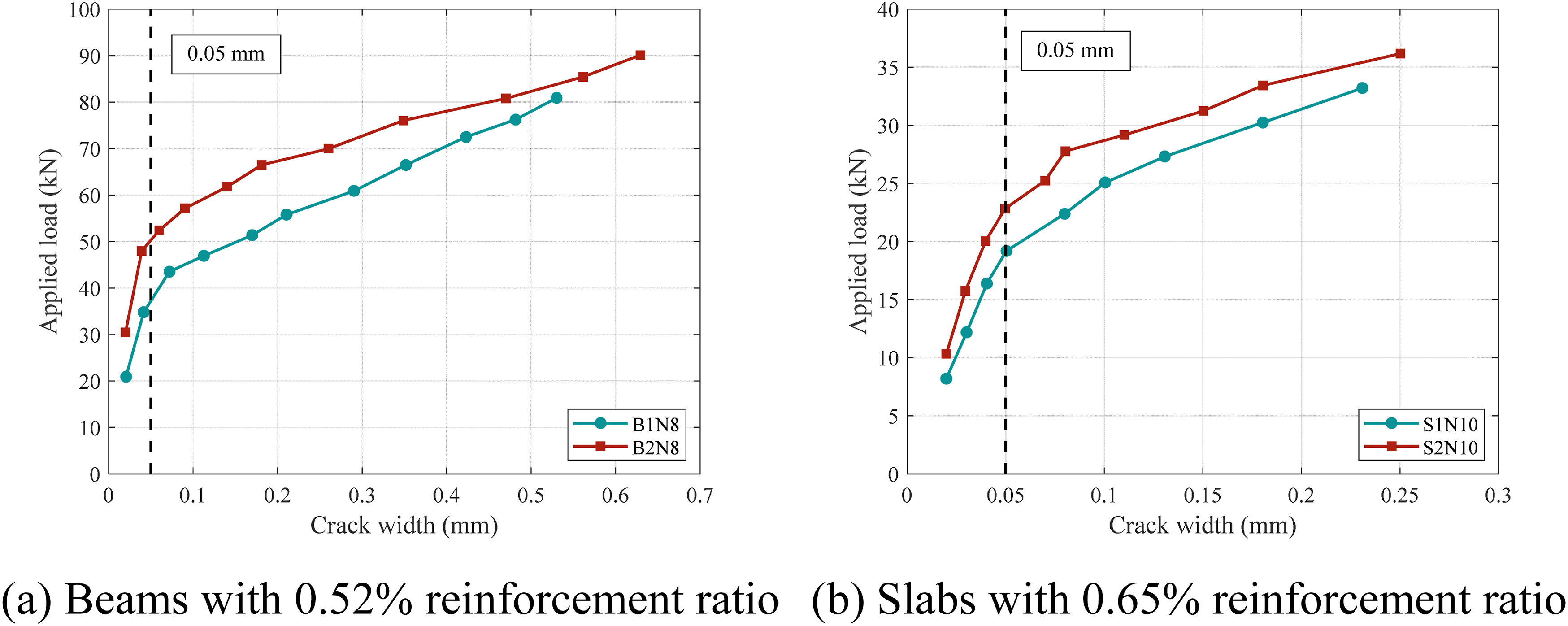
Crack width is a critical parameter for assessing structural serviceability, particularly for marine structures where durability is paramount. During testing, critical cracks, identified by their maximum width, occurred predominantly at the mid-span or beneath the loading points. To assess the effects of reinforcement ratio and steel fibre content on crack widths, Figure 11 shows the relationship between applied load and maximum crack width for specimens with 2% steel fibre content, whereas Figure 12 presents results for specimens with reinforcement ratios of 0.52% (beams) and 0.65% (slabs). For safety and to prevent equipment damage, crack widths were measured only during the serviceability stages and were not recorded near the ultimate state. Effect of reinforcement ratio on crack width development. Effect of steel fibre content on crack width development.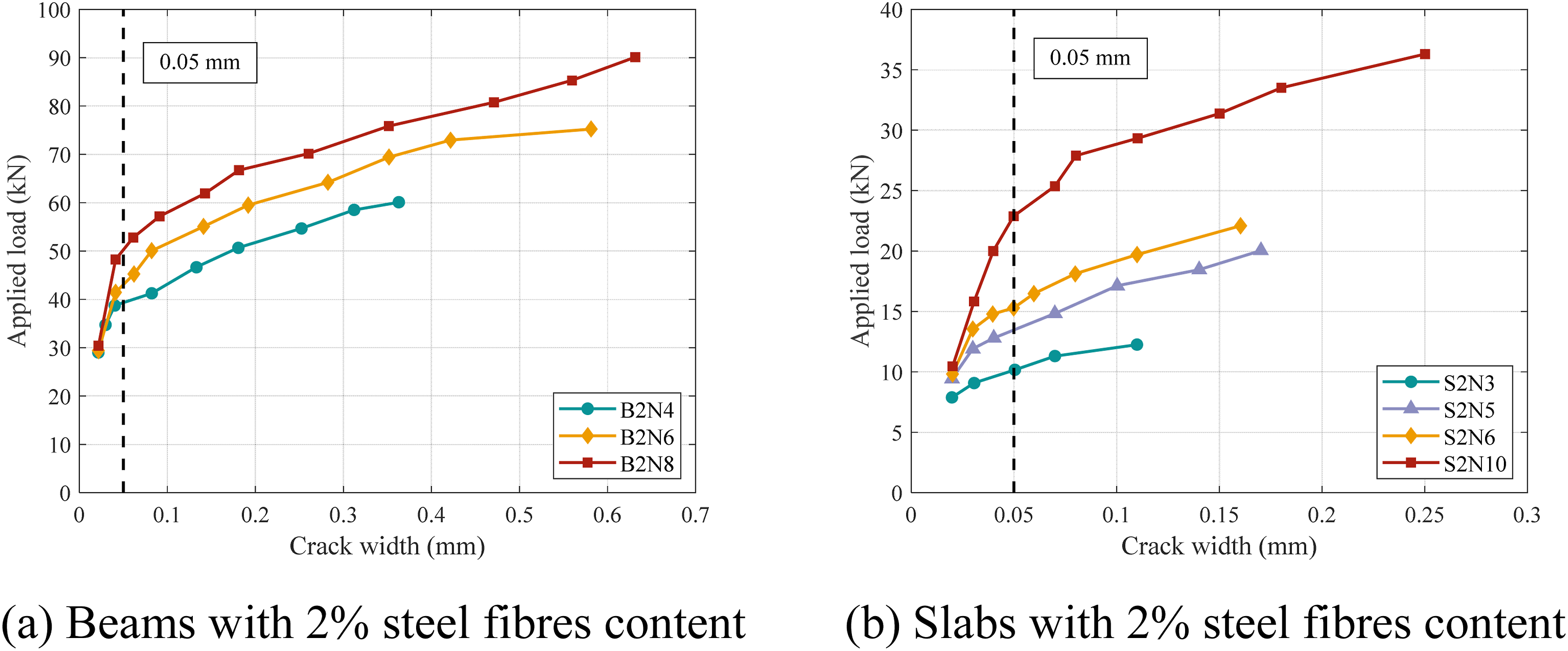
Before the formation of a dominant crack, load-crack width relationships exhibited a consistent, nearly linear trend across all specimens. A critical crack width of 0.05 mm was identified, beyond which crack growth accelerated and structural stiffness noticeably reduced (Figure 9). This critical threshold is consistent with durability limits recommended by the AFGC (2013) and ACI 239R-18 (2018), suggesting its applicability to thin-walled UHPC members reinforced with unprestressed steel strands.
As shown in Figure 11, increasing reinforcement ratios effectively reduced crack widths and slowed their progression. Figure 12 demonstrates that specimens containing 2% steel fibres content exhibited significantly narrower cracks and slower crack progression compared with those with 1% fibres at identical loads, emphasising improved crack control associated with higher steel fibre contents. This trend was consistently observed in both beams and slabs, supporting the established understanding that steel fibres enhance post-cracking performance and delay the failure of the UHPC matrix (Habel et al., 2007; Zhang et al., 2023). This improvement is attributed to the fibre bridging mechanism, which transfers tensile stresses effectively across cracks, reducing localised tensile damage and thus limiting crack width (Zhang et al., 2023).
According to GB/T 31387 (2015), the crack width limits for UHPC align with those set by GB 50010 (2015), which defines maximum permissible crack widths based on environmental exposure: 0.30 mm for dry environment (Class I), 0.20 mm for humid environment (Class II), and 0.10 mm or no visible cracks for corrosive or freeze-thaw conditions (Class III), which are pertinent to marine applications. Figure 13(a) compares corresponding service loads for each specified crack width limit (0.10, 0.20, and 0.30 mm). As measured crack widths in slab specimens remained relatively small, only the 0.10 mm limit is presented in Figure 13(b). Service loads corresponding to different specified crack width limits.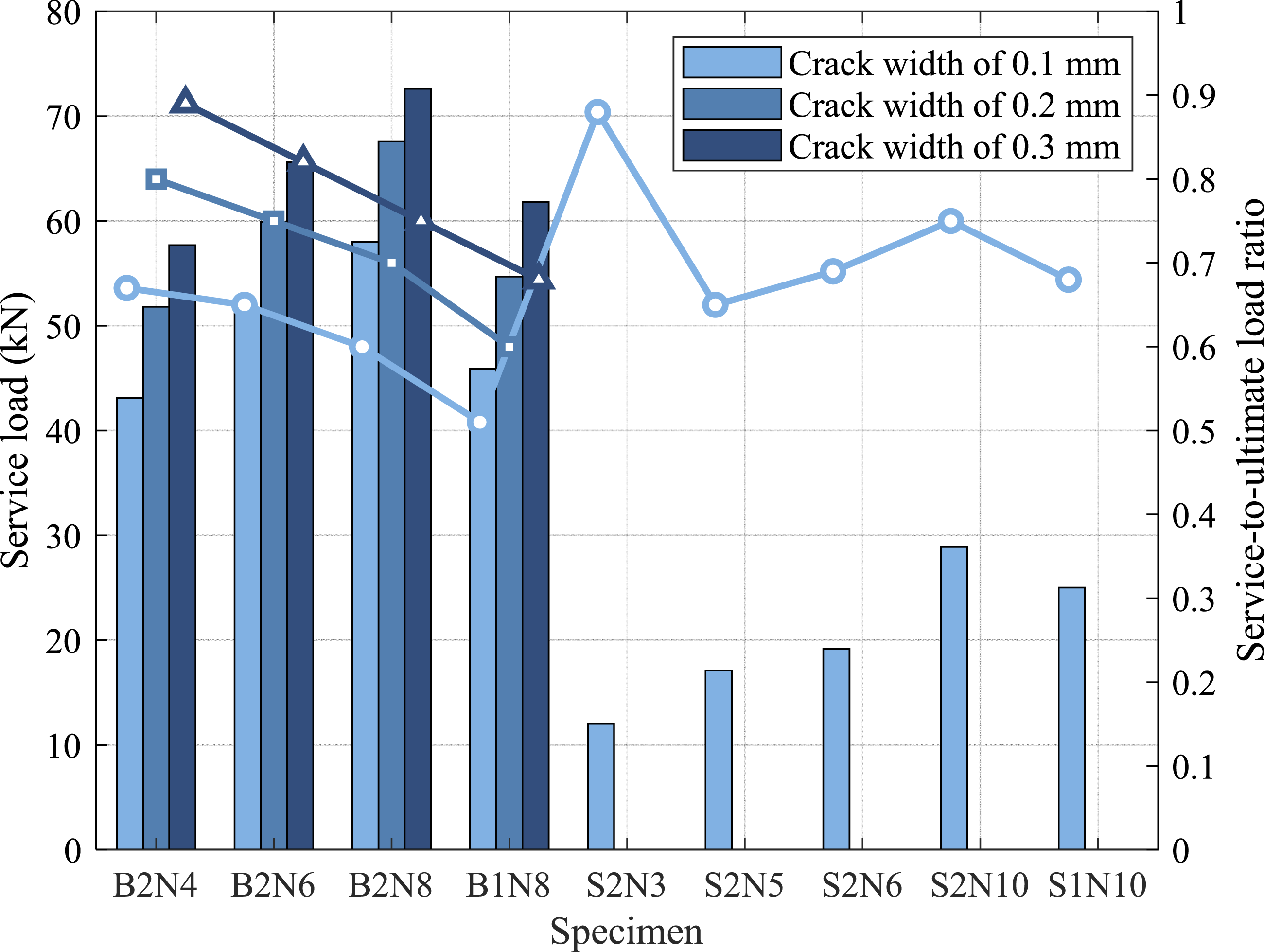
At the 0.10 mm crack limit, specimens B2N4, B2N6, and B2N8 supported service loads of 43.13 kN, 51.58 kN, and 58.00 kN. Increasing the allowable crack width to 0.20 mm resulted in an increase of 17%–20% in the service load; at 0.30 mm, the increase reached approximately 35%. A near-linear relationship between service load and reinforcement ratio was observed for both beams and slabs, irrespective of the crack width limits. However, for beam specimens, the ratio of service load to ultimate load decreased with increasing reinforcement, indicating reduced material efficiency at higher reinforcement ratios. This trend was not observed in slab specimen S2N10, which exhibited concrete crushing failure and underutilisation of the steel strands, resulting in a higher service-to-ultimate load ratio compared with specimens S2N5 and S2N6. This indicates that over-reinforced members may offer more efficient crack control at the SLS compared with under-reinforced configurations.
Moreover, specimens B1N8 and B2N4 attained nearly identical service loads across all crack width limits. This suggests that increasing the reinforcement ratio from 0.26% to 0.52% can yield benefits comparable to those from increasing the steel fibre content from 1% to 2% in the beam specimens. Specimen B1N8 had a lower ratio of service-to-ultimate load, ranging from approximately 85% to 91% of that for specimen B2N8, depending on the crack width limit considered. As the permissible crack width increased, this difference diminished. This observation reflects the reduced bridging efficiency of steel fibres at wider crack widths, particularly once the crack width exceeds 0.2–0.3 mm, which is consistent with recommendations from AFGC (2013). Overall, appropriately increasing steel fibre content significantly enhances crack control performance at the serviceability stage, particularly under strict crack width limits relevant to marine environments.
Strain development and distribution
The strain distributions along the section depth, based on the measured data, are shown in Figures 14 and 15, where the vertical axis represents the distance from the bottom surface of the section. Throughout pre- and post-cracking stages, most specimens exhibited nearly linear longitudinal strain distributions relative to the neutral axis, which validates the plane section assumption (Feng et al., 2021; Yuan et al., 2020). Mid-span sectional strain distributions in beam specimens. Mid-span sectional strain distributions in slab specimens.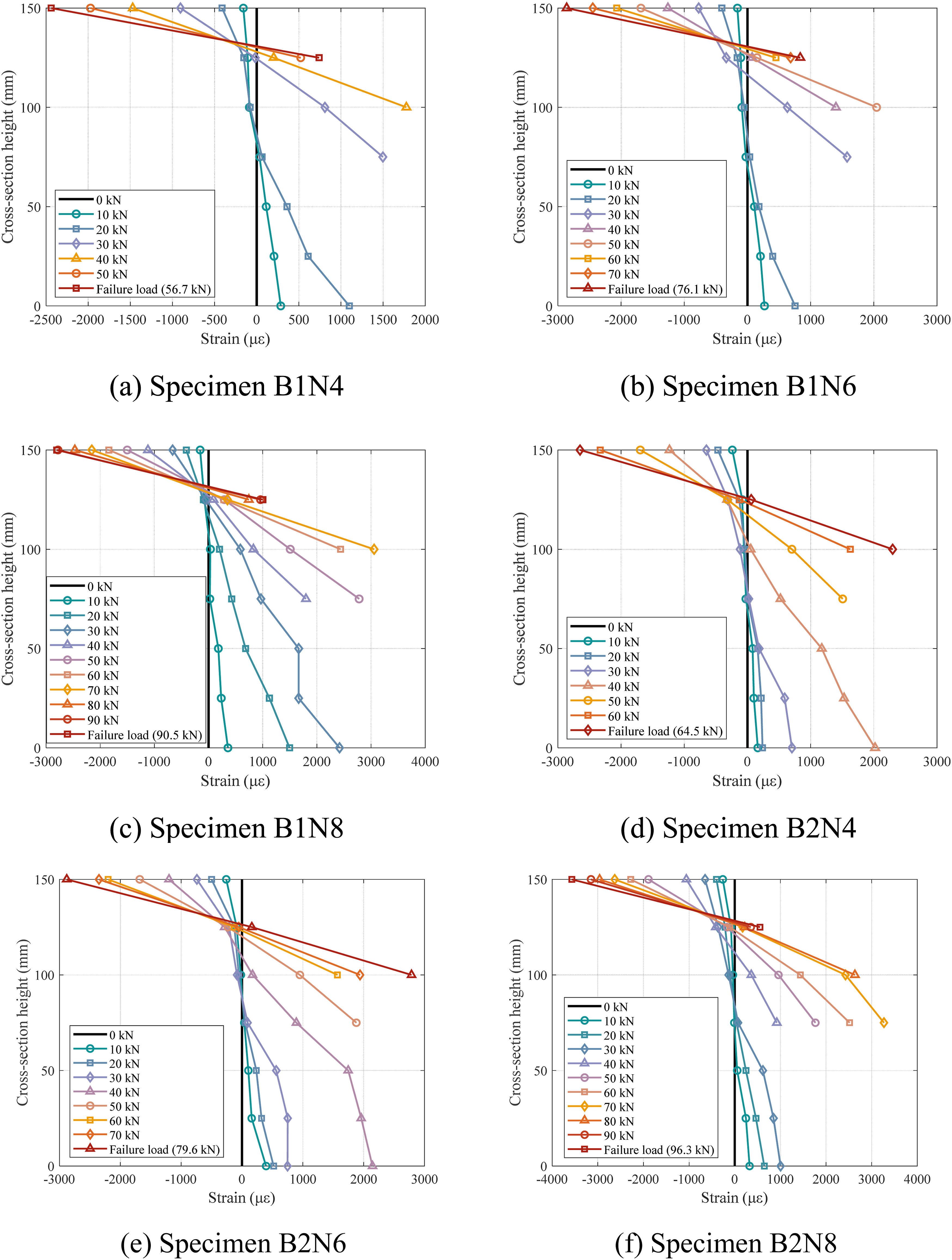
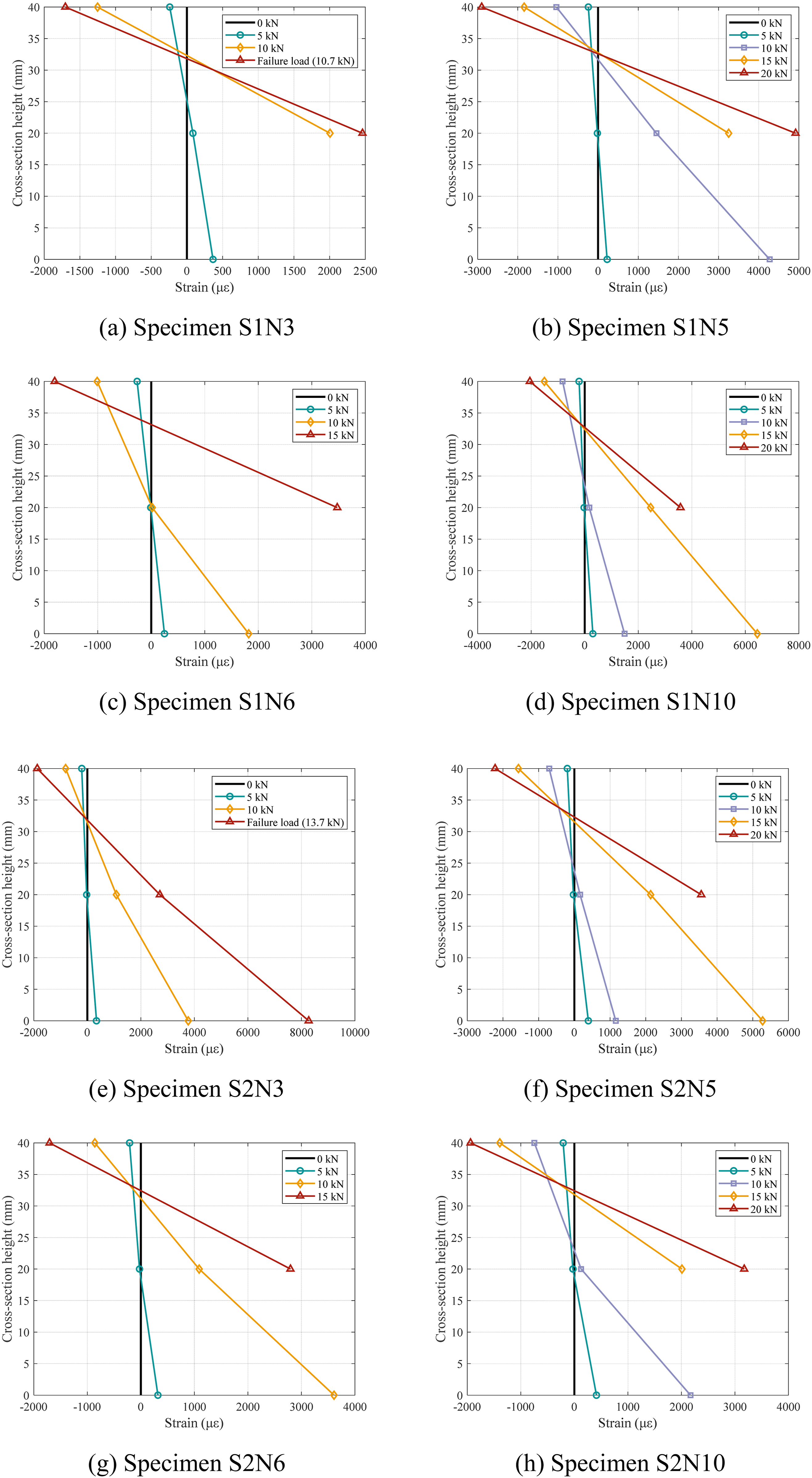
Initially, tensile and compressive strains were approximately symmetrical, which placed the neutral axis near the mid-depth of the section. Upon the initiation of cracking, the neutral axis shifted upwards, reflecting an increase in curvature (Figures 14 and 15) and a significant reduction in flexural stiffness (Table 4). A comparison at equivalent load levels reveals that higher reinforcement ratios corresponded to lower strain values, indicating improved deformation resistance. Additionally, due to the high tensile strength and ductility of UHPC containing steel fibres, a higher steel fibre content effectively suppressed the development of post-cracking tensile strain, suggesting that the fibres shared tensile loads and delayed stiffness degradation.
The maximum compressive strains measured in the UHPC are summarised in Table 4. The specimens that failed due to concrete crushing (i.e., S1N10 and S2N10) exhibited maximum compressive strains exceeding 4500 με, whereas those that failed by steel strand rupture generally showed lower compressive strain values. In general, a positive correlation was observed between the maximum compressive strain and both the reinforcement ratio and the steel fibre content. However, the reinforcement ratio was found to have a more dominant effect on the failure mode, as illustrated in Figure 10, indicating that the maximum compressive strain at failure was more sensitive to changes in reinforcement ratio than in the steel fibre content.
Prediction model
The experimental results were evaluated through comparison with numerical predictions derived from a theoretical model developed by Xia et al. (2024). This theoretical model employs an enhanced deflection method, the accuracy of which for predicting the flexural behaviour of slender UHPC members was previously validated by Wu et al. (2024).
Theoretical analysis
The theoretical analysis is based on classical Euler–Bernoulli beam theory, which assumes that plane sections remain plane after deformation and neglects shear effects. The cross-section analysis was first conducted by discretising each section into several thin layers parallel to the neutral axis. A linear strain distribution across the section depth was assumed, and the internal stresses were computed iteratively using the Newton–Raphson method, based on the material constitutive models. This procedure enabled the derivation of the moment–curvature relationships. The specific constitutive material models are detailed in Material Constitutive Models. A perfect bond between the UHPC and embedded steel strands was assumed for all cross-sections (Wu et al., 2024; Zhan et al., 2024).
At the structural member level, both the beam and the slab specimens were idealised as one-dimensional elements along their centroidal axes. Considering geometric and loading symmetry about the mid-span, only one half of each member was modelled, and the centroidal axis of this half-span was discretised into a series of straight segments.
The boundary conditions were established to replicate the experimental setup. The left end of the first segment, representing the simply supported boundary, was vertically restrained but permitted free rotation (i.e., zero bending moment). The right end of the last segment, representing the mid-span, was modelled as a sliding hinge, which permitted horizontal displacement while restraining vertical translation and rotation.
An incremental vertical displacement corresponding to the mid-span deflection was applied at the right boundary of the final segment. At each load increment, the support reactions and rotations at the left end were iteratively adjusted until both prescribed displacement and zero-rotation conditions at mid-span were satisfied simultaneously. During iterative analysis, each initially straight segment was updated into a deformed circular arc, for which the axial strain and curvature were determined from the computed bending moment and the established moment–curvature relationship. Geometric compatibility was enforced between adjacent arc segments to ensure continuity at their intersection points. Each pair of adjacent arcs was required to be tangent at their shared point, enabling sequential and stable computation of deformation across the half-span.
Material constitutive models
The uniaxial tensile and compressive stress–strain curves for the UHPC, adopted for section analyses are shown in Figure 16, with compressive stress and strain considered positive. The curves for all the specimens are presented, showing similar constitutive behaviour (as shown in the subfigure in Figure 16) irrespective of steel fibre content being 1% or 2%. Notably, the slabs exhibited superior tensile ductility compared with the beams, which reflects the effect of section depth on the effective contribution of steel fibres in UHPC (18-710, 2016; Yoo et al., 2016). Material constitutive models for UHPC adopted in the theoretical analysis.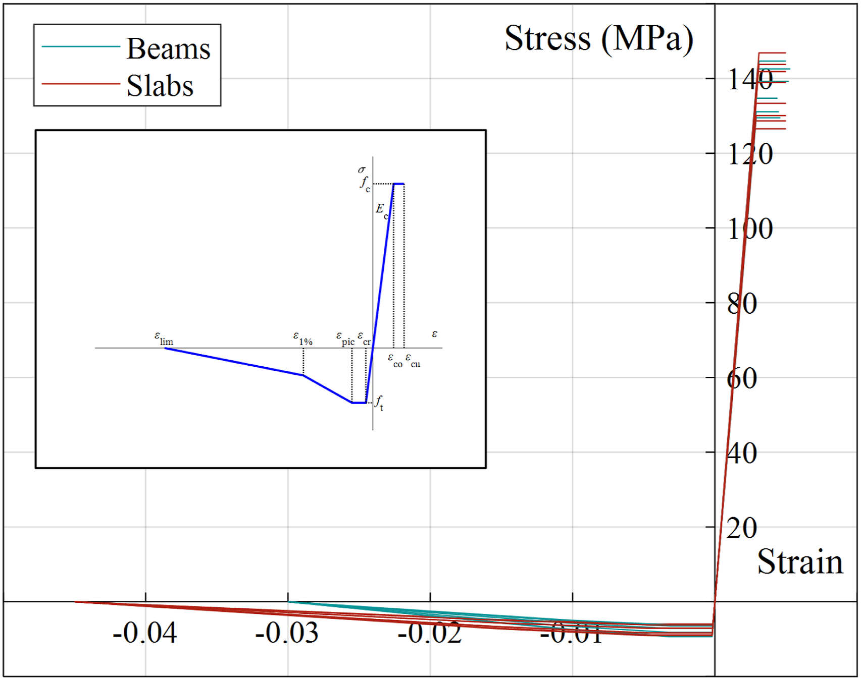
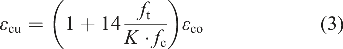
For the compressive behaviour, the constitutive model from NF P 18-710 (18-710, 2016) was applied, with a reduction factor of 1.0. The corresponding stress–strain relationship is defined by equations (1)–(3), with the concrete strength as the governing parameter.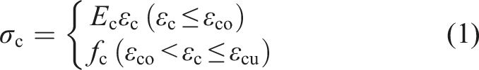

The elastic modulus (
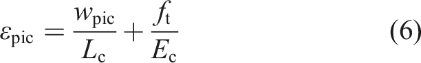
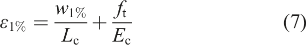
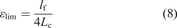
For the tensile behaviour, the multi-linear constitutive model recommended in NF P 18-710 (2016) was adopted (Figure 16). This model comprises an initial linear-elastic segment up to the tensile strength, followed by a yield plateau corresponding to matrix cracking and fibre bridging, and two subsequent descending branches representing a progressive reduction in stiffness due to fibre bridging effects, as described by equations (5)–(8).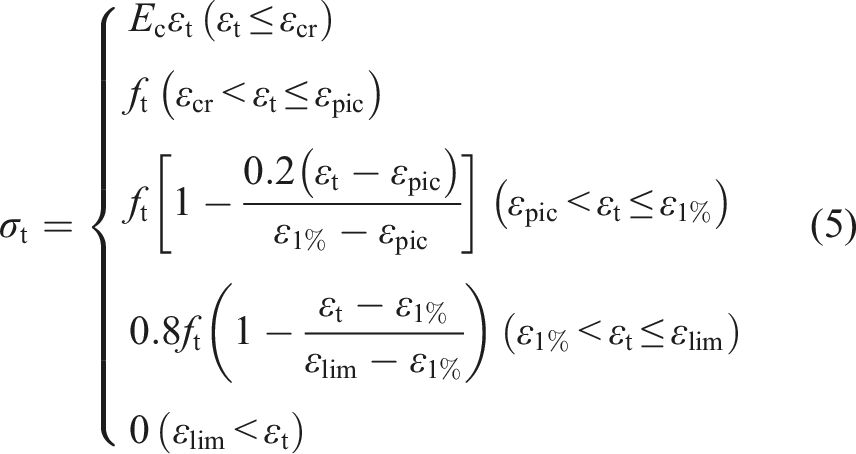
The steel strands exhibited no distinct yield plateau, which rendered traditional idealised bilinear models inappropriate (GB-50010, 2015). Therefore, a piecewise polynomial fit derived from the experimental stress–strain data (Figure 5) was employed to characterise the behaviour of the strands.
Model validation
Figures 17 and 18 compare the experimental and predicted load-deflection curves for the beams and slabs. The model accurately captured both the pre-cracking and post-cracking behaviour for all tested specimens. Model validation: comparison of predicted and experimental load-deflection curves for beam specimens. Model validation: comparison of predicted and experimental load-deflection curves for slab specimens.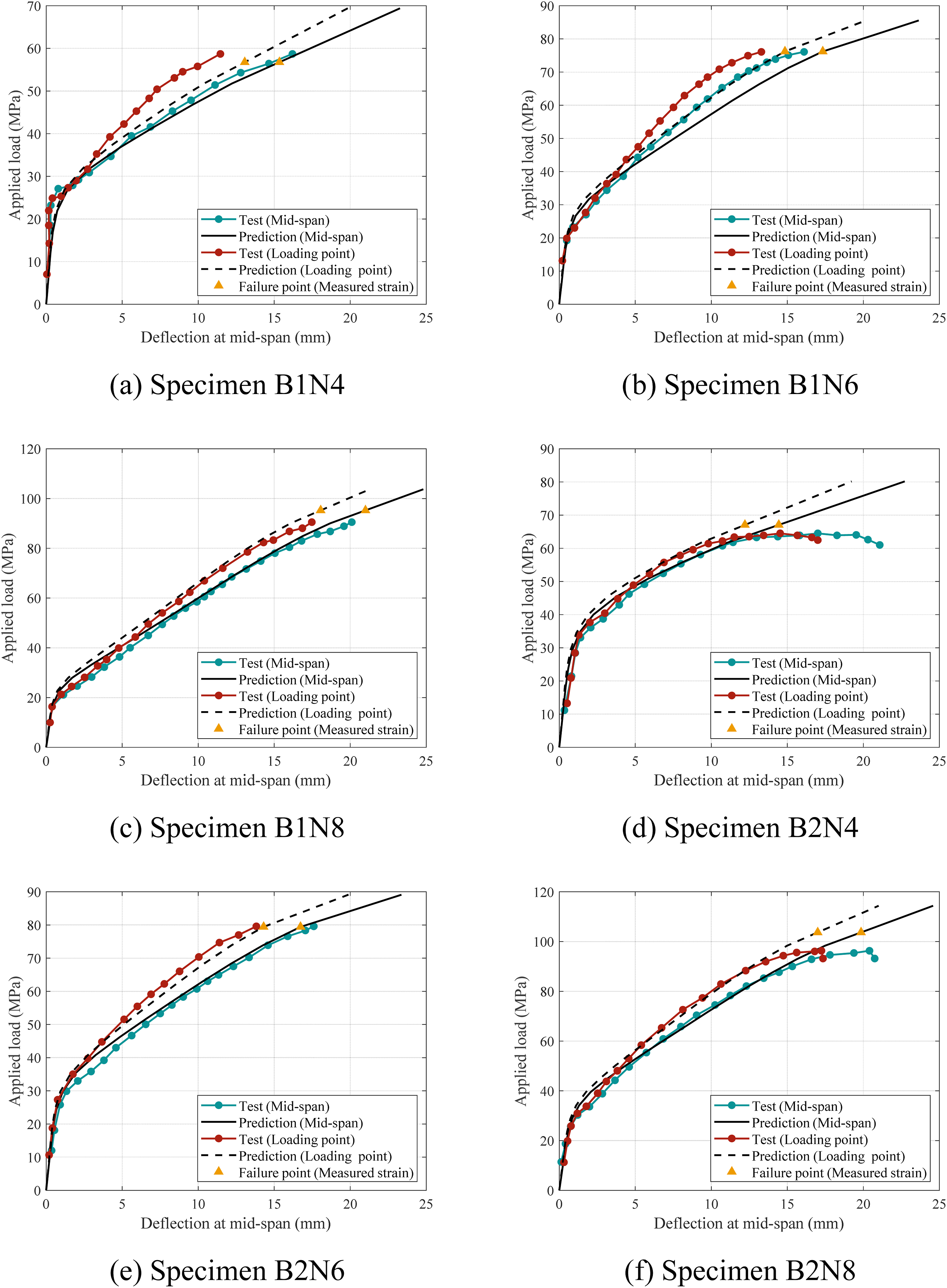
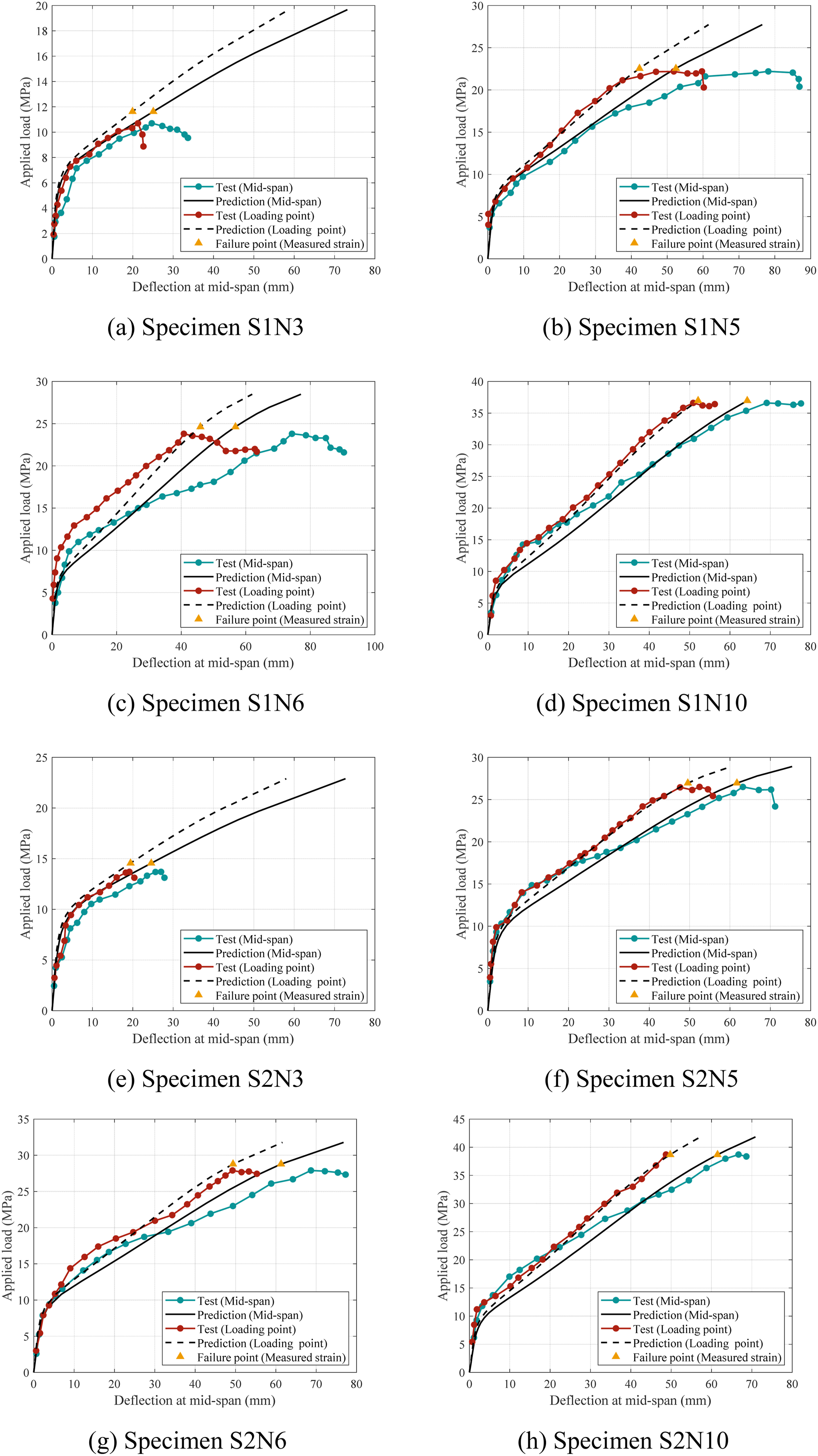
Two failure modes were defined at the endpoints of the curves based on both material models and experimental observations: tensile rupture of strands in under-reinforced members, and concrete crushing in over-reinforced members. The numerical model terminated when either: (i) tensile strain in strands reached the rupture threshold, or (ii) UHPC compressive strain exceeded the limit defined by NF P 18-710. These criteria marked the failure limit states, indicating the end of the predicted load-deflection response. Experimentally observed failure states, characterised by measured extreme compressive strains of UHPC at peak loads, were also calculated and are indicated in the figures. The predicted failure points consistently occurred later than experimental observations, especially for specimens with low reinforcement ratios. However, the ultimate states derived from experimentally measured strains provided accurate predictions, particularly with regard to the peak loads.
Figure 19 presents a comparison between experimental and predicted results for both transition loads and peak loads. For the peak loads shown in Figure 19(a), most predictions fell within an acceptable margin of error, with a maximum deviation of approximately 20%. In general, the theoretical predictions tended to slightly overestimate the experimental results. This is primarily due to idealised assumptions in the analytical models, such as perfect bonding and the neglect of local imperfections (Zhan et al., 2024). However, this trend did not apply to specimens with low reinforcement ratios (i.e., 0.19% in specimens S1N3 and S2N3), for which the peak load relied significantly on fibre bridging effects. As discussed in Load-deflection Behaviour and Load-carrying and Deformation Capacities, fibre bridging effects are highly sensitive to fibre orientation, which makes accurate numerical modelling particularly challenging. For the transition load shown in Figure 19(b), greater variability was observed, with a maximum deviation of approximately 30% and an average deviation of around 3.6%. These discrepancies primarily arose from the random and non-uniform fibre distribution within the UHPC matrix, which deviates from the homogeneity assumption in the analytical model (Feng et al., 2021; Yoo et al., 2016). Accuracy of the theoretical model in predicting key performance indicators.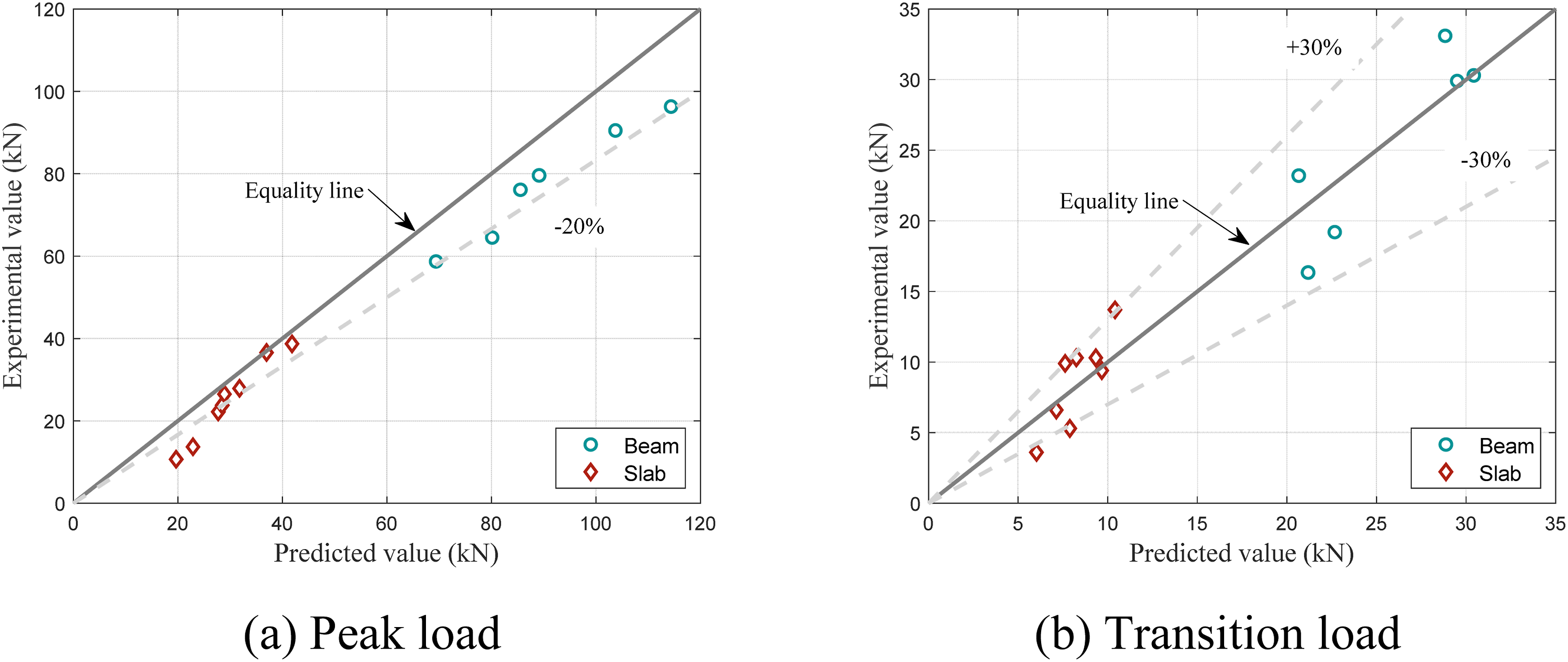
Conclusions
This study investigated the flexural performance of thin-walled UHPC members reinforced with unprestressed steel strands through four-point bending tests on six beams and eight slabs. Additionally, a deflection-based theoretical model was developed to predict the flexural response. Based on the experimental and analytical results, the following conclusions are drawn: (1) The failure mode depended primarily on the reinforcement ratio rather than the steel fibre content. Two main failure modes were observed: the tensile rupture of steel strands at lower reinforcement ratios and concrete crushing at higher ratios. (2) An increased steel fibre content markedly enhanced the transition load with negligible size-dependent effects, whereas the reinforcement ratio had a minimal effect. (3) Post-cracking stiffness was enhanced by a synergistic interaction between the steel fibre content and the reinforcement ratio: the contribution from the fibres was most pronounced in lightly reinforced members, whereas increasing the reinforcement ratio yielded greater stiffness gains in members with a lower steel fibre content. (4) A near-linear correlation was observed between the reinforcement ratio and the ultimate load capacity. However, increasing the reinforcement ratio offered limited improvement to deformation capacity and, when excessive, reduced it by altering the failure mode. (5) Both an increased steel fibre content and a higher reinforcement ratio improved crack control, which is critical for the durability of marine structures. Steel fibres were particularly effective under stringent crack width limits, while a higher reinforcement ratio also enhanced crack control despite reducing material efficiency. (6) The developed theoretical model accurately predicted the flexural behaviour. The predictions for the peak load had a maximum deviation of approximately 20%, and the average error for the transition load was about 3.6%.
Footnotes
Acknowledgments
The authors gratefully acknowledge the financial support received from the Natural Science Foundation of Zhejiang Province (Project No.: LY21E080003).
Funding
The authors disclosed receipt of the following financial support for the research, authorship, and/or publication of this article: Natural Science Foundation of Zhejiang Province (Project No.: LY21E080003).
Declaration of conflicting interests
The authors declared no potential conflicts of interest with respect to the research, authorship, and/or publication of this article.
Data Availability Statement
Some or all data, models, or code that support the findings of this study are available from the corresponding author upon reasonable request.