
Abstract
A novel Nonlinear Eddy Current Damping (NL-ECD) design method for a Triple-magnet Magnetic Suspension Dynamic Vibration Absorber (TMSDVA) is proposed, modelled, and tested. The implementation of the NL-ECD design method is completely passive and does not require an external energy supply. First, the mathematical model of the TMSDVA vibration reduction system is established. Additionally, the NL-ECD calculation model is also derived. The NL-ECD coefficient can be designed and adjusted by changing the dimensional parameters of the damping tube. Then the correctness of the NL-ECD derivation process is verified through simulations and experiments. It is found that the NL-ECD coefficient is strongly related to the position of the moving magnet. And the simulation results show the same trend as the experimental results. Next, the dynamic responses of the TMSDVA with NL-ECD are studied. Using NL-ECD can not only eliminate higher branch responses in the TMSDVA vibration reduction system, but also retain non-linear dynamics response characteristics of the system. As a result, a better vibration reduction effect of the TMSDVA is obtained. Moreover, the NL-ECD design method proposed in this paper can be either applicable to the TMSDVA or applicable to other types of magnetic DVAs using cylindrical magnets or ring magnets.
Keywords
Highlights
A novel Nonlinear Eddy Current Damping (NL-ECD) design method is proposed, modelled, and tested. The realization of the method is completely passive and does not require an external energy supply. The NL-ECD coefficient of the Triple-magnet Magnetic Suspension Dynamic Vibration Absorber (TMSDVA) can be designed and adjusted by changing the dimensional parameters of the damping tube. Using NL-ECD can both eliminate higher branch responses and retain non-linear response characteristics in the TMSDVA vibration reduction system. The NL-ECD design method can also be applicable to other types of magnetic DVAs utilizing cylindrical magnets or ring magnets.
Introduction
Dynamic Vibration Absorber (DVA), a passive vibration reduction device, was first proposed by Frahm in 1909 (Xu, 2015). DVAs have been widely used in the vibration control of engineering structures. Linear Dynamic Vibration Absorber, which is also called Tuned Mass Damper (TMD), is usually composed of a linear stiffness element, a mass block, and a damping component (Liu et al., 2007). Thanks to its large damping, TMD can have a broad vibration reduction frequency band. However, due to the high demand for the damping component, TMD usually requires more installation space. And TMD may lead to the occurrence of a significant resonance frequency offset of the vibration reduction object (Den Hartog, 1947; Ormondroyd and Den Hartog, 1928). Roberson (Roberson, 1952) indicated that introducing nonlinear stiffnesses to DVAs can also expand the vibration reduction frequency band and enhance the robustness of DVAs. And the nonlinear system will not exhibit an obvious resonance peak when the Nonlinear Dynamic Vibration Absorber (NLDVA) performs a good vibration reduction effect. There are many kinds of NLDVAs, including cubic stiffness NLDVAs (Oueini et al., 1999), piecewise stiffness NLDVAs (Pun and Liu, 2000) and tuned stiffness NLDVAs (Walsh and Lamancusa, 1992), et al. Nonlinear Energy Sink (NES) is a kind of NLDVA that can effectively transfer vibration energy from the primary structure to itself and dissipate it through its damping. NES was first proposed and named by Vakakis (Vakakis, 2001). NESs differ from other NLDVAs because of their targeted energy transfer (Zhang et al., 2019), which is fast, unidirectional, and irreversible (Guo et al., 2015). As a result, NESs have received a lot of attention from researchers in recent years. Furthermore, the related theories have gradually matured (Bab et al., 2017; Li et al., 2019; Tsiatas and Karatzia, 2020).
Besides, in the studies of NLDVAs, the researchers have also paid attention to DVAs with magnetic properties. The nonlinear stiffnesses of magnetic DVAs are generated by the interaction between the magnets (Sun et al., 2021; Zhang et al., 2017). Compared with NLDVAs constructed from non-magnetic components, magnetic DVAs greatly reduce the difficulty of obtaining nonlinear stiffness. Many types of magnetic DVAs have been proposed and studied, including those with rods and ring magnet sets (Benacchio et al., 2016; Yamakawa et al., 1977), as well as those with rectangular magnets (Chen et al., 2020). However, existing magnetic DVAs typically require numerous magnets, leading to more complex structures. Furthermore, due to this requirement, magnetic DVAs, which have high installation space requirements, are not conducive to miniaturization.
Although NLDVAs typically possess wide vibration reduction frequency bands, the strong nonlinear stiffnesses in NLDVAs can lead to complex dynamics in the vibration reduction system, resulting in behaviours such as bifurcation and chaotic motion (Chen et al., 2018; Zang and Chen, 2017). Starosvetsky et al. (Starosvetsky and Gendelman, 2009) have investigated bifurcation control of a NLDVA using nonlinear damping. This type of nonlinear damping characteristic is feasible in hydraulic dampers based on the same principle of orifice flow, with the addition of semi-active control (Golafshani and Mirdamadi, 2009). Such damping can be realized in hydraulic dampers containing several on/off orifice valves in a moving piston. These pieces of evidence mean that the realization of the nonlinear damping needs external energy supply. However, for magnetic DVAs, due to the magnetic properties of the magnets, employing Eddy Current Damping (ECD) (Liu et al., 2020b; Lu et al., 2017; Tom et al., 2016) may be a convenient and effective method for eliminating bifurcation behaviours in the system.
Eddy currents can be induced in a good non-magnetic conductor, such as aluminium, because of a moving permanent magnetic source (e.g., a permanent magnet) in the vicinity of the conductor (Bae et al., 2009; Kriezis et al., 1992). The interaction between the induced magnetic field resulting from eddy currents and the external magnetic field generates a braking force, referred to as the ECD force
Based on the aforementioned background, a novel Nonlinear Eddy Current Damping (NL-ECD) design method for a Triple-magnet Magnetic Suspension Dynamic Vibration Absorber (TMSDVA) (Chen et al., 2023a, 2023b, 2023c, 2023d) is proposed, modelled, and tested in this work.
The paper is organized as follows: In Section 2, the structure of the TMSDVA is introduced first. Then the mathematical model of the TMSDVA vibration reduction system and the calculation model of the NL-ECD design method are established. In Section 3, simulations and experiments are conducted to verify the correctness of the derivation process described in Section 2.2. In Section 4, the dynamic responses of the TMSDVA with NL-ECD are analysed to determine how NL-ECD affects the vibration reduction performance of the TMSDVA. Section 5 concludes the paper.
Structure and Mathematical Model
Triple-Magnet Magnetic Suspension Dynamic Vibration Absorber (TMSDVA)
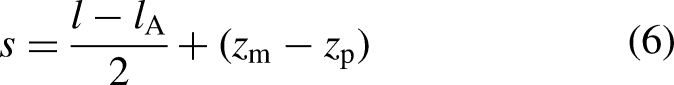
Figure 1(a) shows the schematic diagram of the TMSDVA. The TMSDVA is composed of three cylindrical permanent magnets A, B, C, and a non-magnetic conductive metal tube (damping tube) D1. Both the magnets B and C share the same specifications, which are fixed with the damping tube D1. The position of the magnet B and the magnet C is symmetrical about the centre of the damping tube D1. The magnet A repels not only magnet B, but also magnet C (the magnetic pole arrangements are shown in Figure 1(a)). When the magnet A moves relative to the damping tube D1, eddy currents can be generated on the surface of the tube, which provides linear ECD for the TMSDVA. The ECD coefficient of the TMSDVA can be designed and adjusted by changing the dimensional parameters of the damping tube D1. E is a non-magnetic insulating mass block (such as a rubber block, etc.) attached to the magnet A. The mass block E and magnet A are collectively referred to as a suspension oscillator. The mass of the mass block E can be changed to adjust the overall mass of the suspension oscillator while keeping magnet A unchanged. This facilitates the optimisation of the vibration reduction effect of the TMSDVA. l is the distance between the two fixed magnets B and C (from the upper surface of magnet B to the lower surface of magnet C). s is the distance between the magnet B and the suspension oscillator (from the upper surface of magnet B to the lower surface of the suspension oscillator). When the suspension oscillator is excited to move, s changes accordingly. The material of the tube D1 in this paper is selected as aluminium, and the inner surface of tube D1 is smoothed.
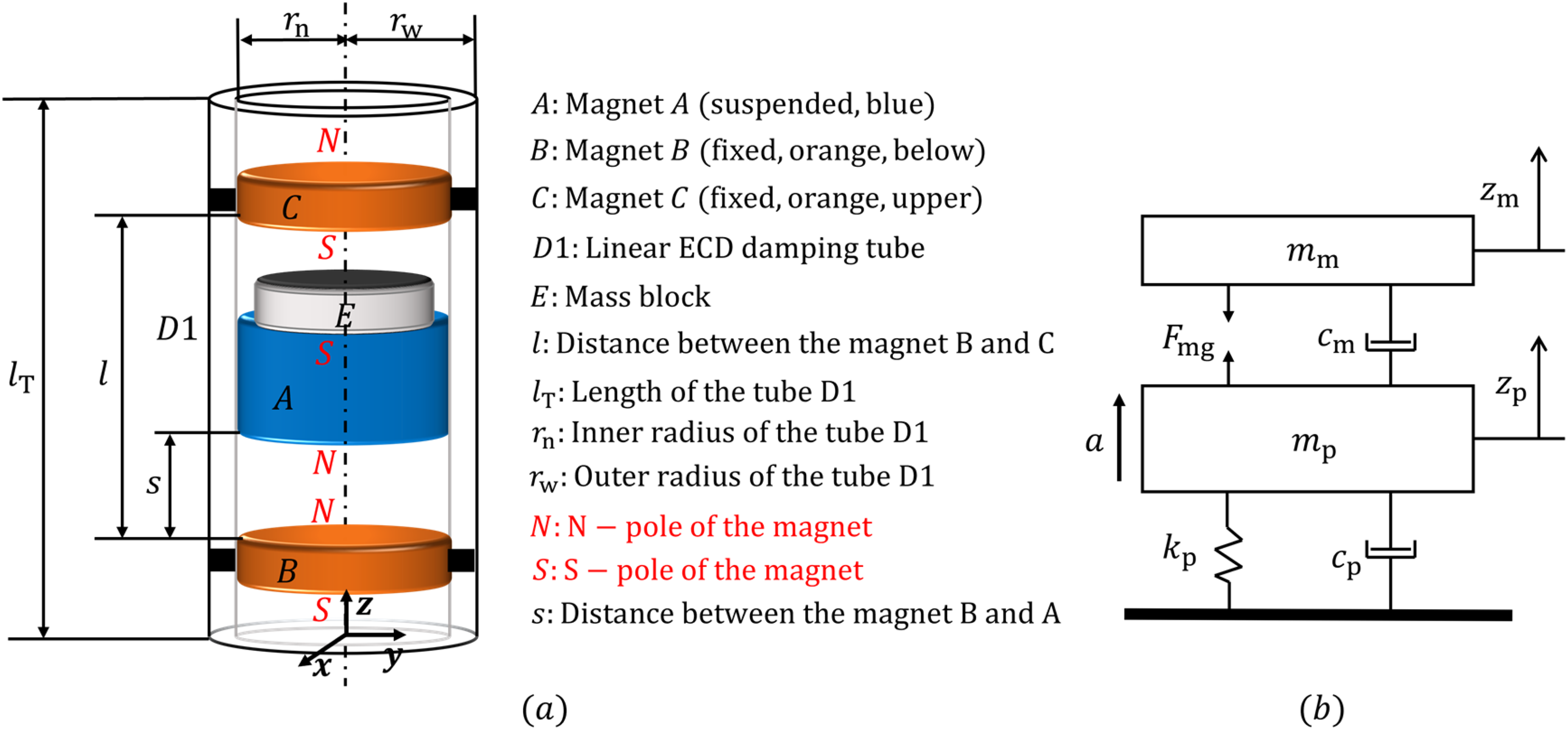
(a) Schematic diagram of the TMSDVA. (b) Equivalent dynamics model of the system with the TMSDVA.
The TMSDVA reported in Figure 1(a) is attached to a vibration reduction object (the primary structure). The equivalent dynamics model of the system is depicted in Figure 1(b). According to Newton's second law, the dynamic equations can be established as:

It is worth noting that the two fixed magnets and tube D1 cannot move relative to the primary structure. Thus,


Nonlinear Eddy Current Damping
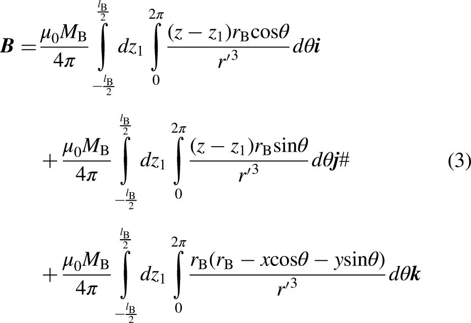
A theoretical model of ECD based on electromagnetic eddy current theory has been proposed in Ref. (Bae et al., 2009). To reduce the computational complexity, the authors approximated the radial magnetic induction of the cylindrical permanent magnet as a constant, which made the results inaccurate. Therefore, based on Faraday's law of electromagnetic induction, the NL-ECD calculation model considering the non-uniformly distributed radial magnetic induction of the permanent magnet is established in this section.
To establish the NL-ECD calculation model, a linear ECD calculation model must be established first. Figure 2 shows the schematic diagram of the linear ECD equivalent calculation model. It is assumed that the eddy current moves only along the conductor plane perpendicular to the axis of the damping tube D1. The magnet A can only move inside tube D1. In other words, the length of the damping tube should be larger than the height of magnet A. Besides, because of the unpredictable tilts of magnet A inside the damping tube, the tilts of magnet A are not considered in our calculation model. A Cartesian coordinate system (
Schematic diagram of the linear ECD equivalent calculation model.
From Eq. (3), the value of
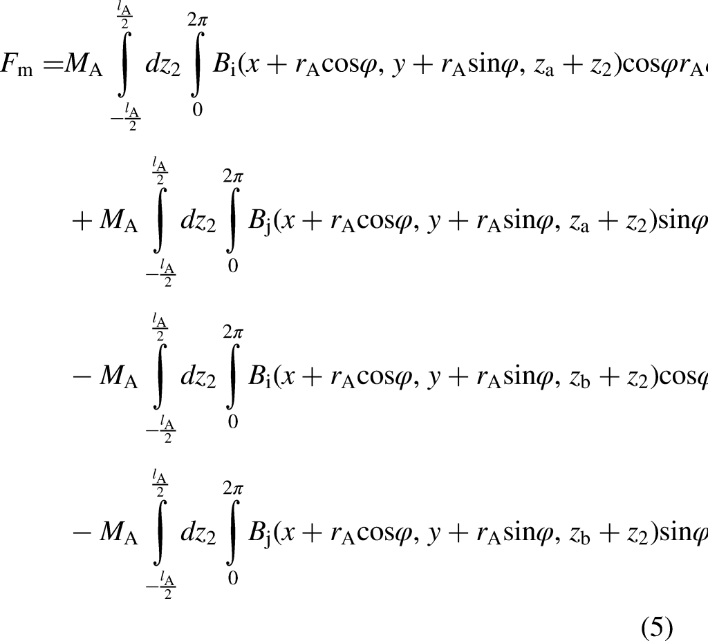
As shown in Figure 2, magnet A moves along the z -axis. We assume that there is a closed loop (grey circle in the top view) in a micro-segment


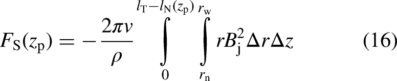
The equation of the S-pole force acting on magnet A has the same form as that of the N-pole force. However, the length of the damping tube subjected to the S-pole force of magnet A is equal to


Schematic diagram of the NL-ECD equivalent calculation model.
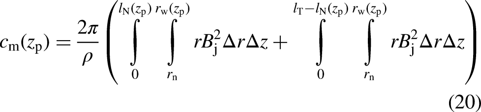
From the figure, when magnet A is at different positions inside the damping tube D2, the corresponding thickness of the tube D2 is different. The outer radius
Simulation and Experimental Verification
In this section, simulations and experiments are carried out to verify the correctness of the NL-ECD calculation model. First, the magnetic induction of the magnet A should be measured through experiments. And the experimental data need to be compared with simulation magnetic induction results to find the actual magnetization of magnet A. The height and radius of magnet A are 29.5 mm and 14.75 mm, respectively. Figure 4 shows the magnetization measurement system. The Gaussmeter was used to measure the magnetic induction of magnet A along the

Magnetization measurement system.
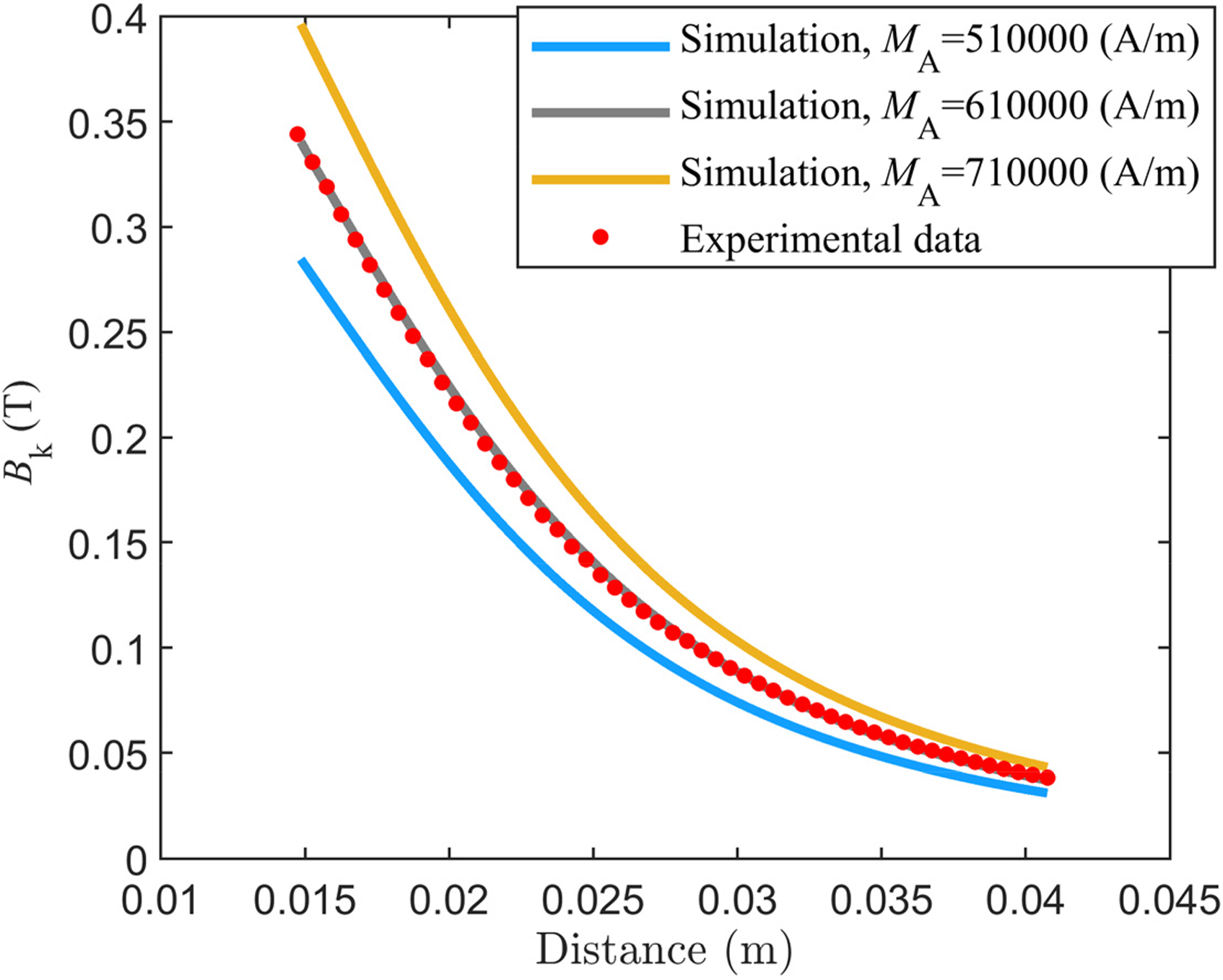
Magnetic induction of magnet A along the z -axis.
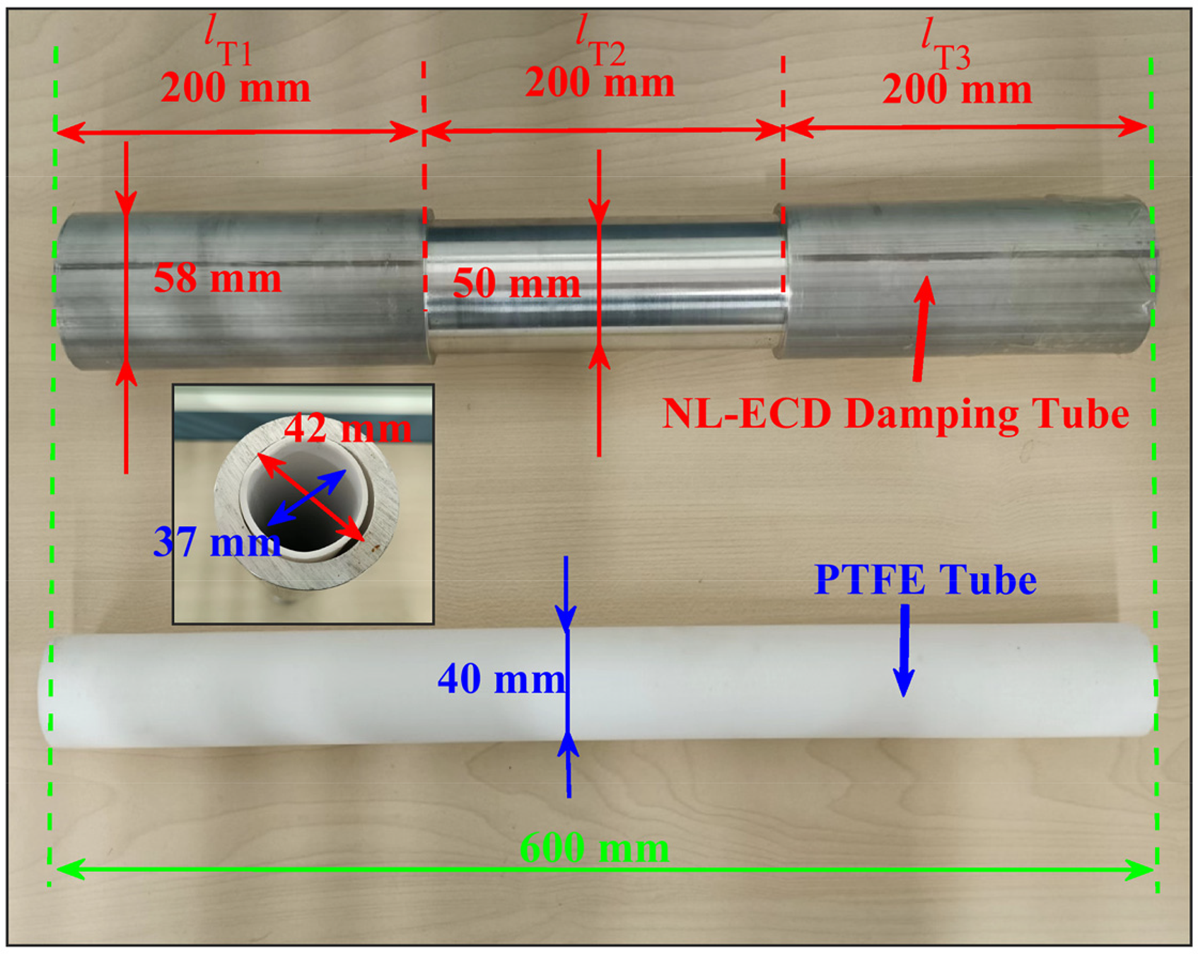
Figure 6 shows the physical map of the NL-ECD damping tube. The inner diameter of the damping tube is 42 mm. The total length of the damping tube is 600 mm. All three segments (
Physical map of the NL-ECD damping tube.
The parameters of magnet A and NL-ECD damping tube are substituted into Eq. (20). Based on the above parameters and the direction of the magnet velocity v, it can be calculated that

Simulation results of NL-ECD coefficients when magnet A is at different positions inside the damping tube.
Because of the structural features of the TMSDVA displayed in Figure 1(a), the movement of magnet A cannot exceed the two fixed magnets. It can also be said that magnet A usually moves near the centre of the damping tube. Hence, magnet A is mainly affected by the NL-ECD coefficients near the centre of the damping tube, such as the NL-ECD coefficients in the interval of [−0.15 m, −0.45 m]. Therefore, the NL-ECD coefficients shown in the interval are the focus of further study.
Since eddy currents can only be generated when magnet A and the damping tube move relatively, it is difficult to obtain the NL-ECD coefficients through direct experimental measurements. Therefore, we choose to indirectly verify the correctness of the NL-ECD force calculation model in Section 2.2 by measuring the motion state of magnet A under the joint action of gravity and the NL-ECD force. Figure 8 depicts the NL-ECD coefficient measurement system. The NL-ECD damping tube is first fixed vertically using a gripper. Then magnet A is placed vertically at the top of the damping tube so that magnet A can fall freely in the tube. An acceleration sensor was attached to magnet A to measure the falling acceleration of magnet A. Finally, the acceleration data can be input into a computer through a signal acquisition device. The sampling frequency of the signal acquisition device is 1.652 kHz.
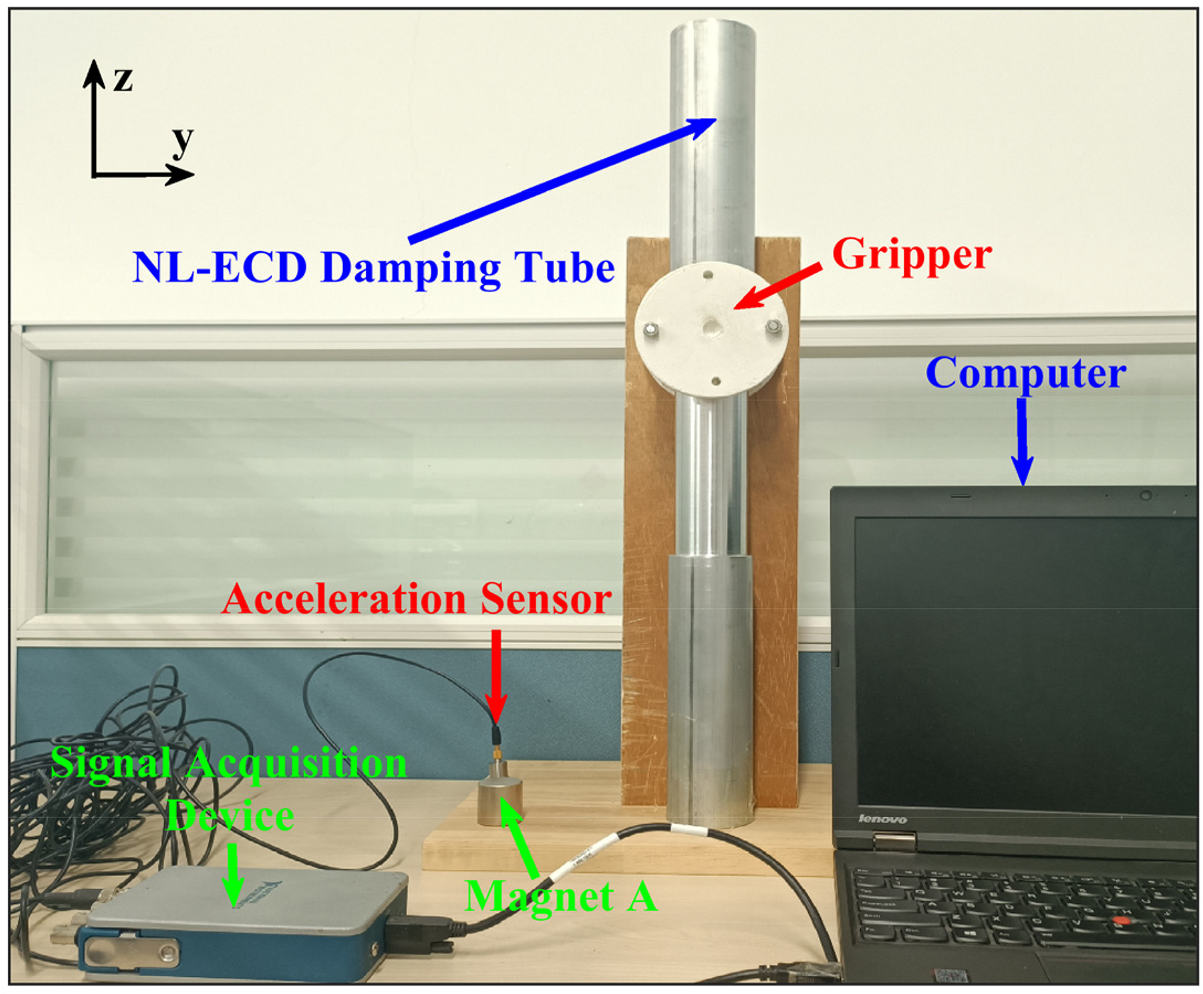
NL-ECD coefficient measurement system.
The dynamic equation for the motion of magnet A in the damping tube can be written as:

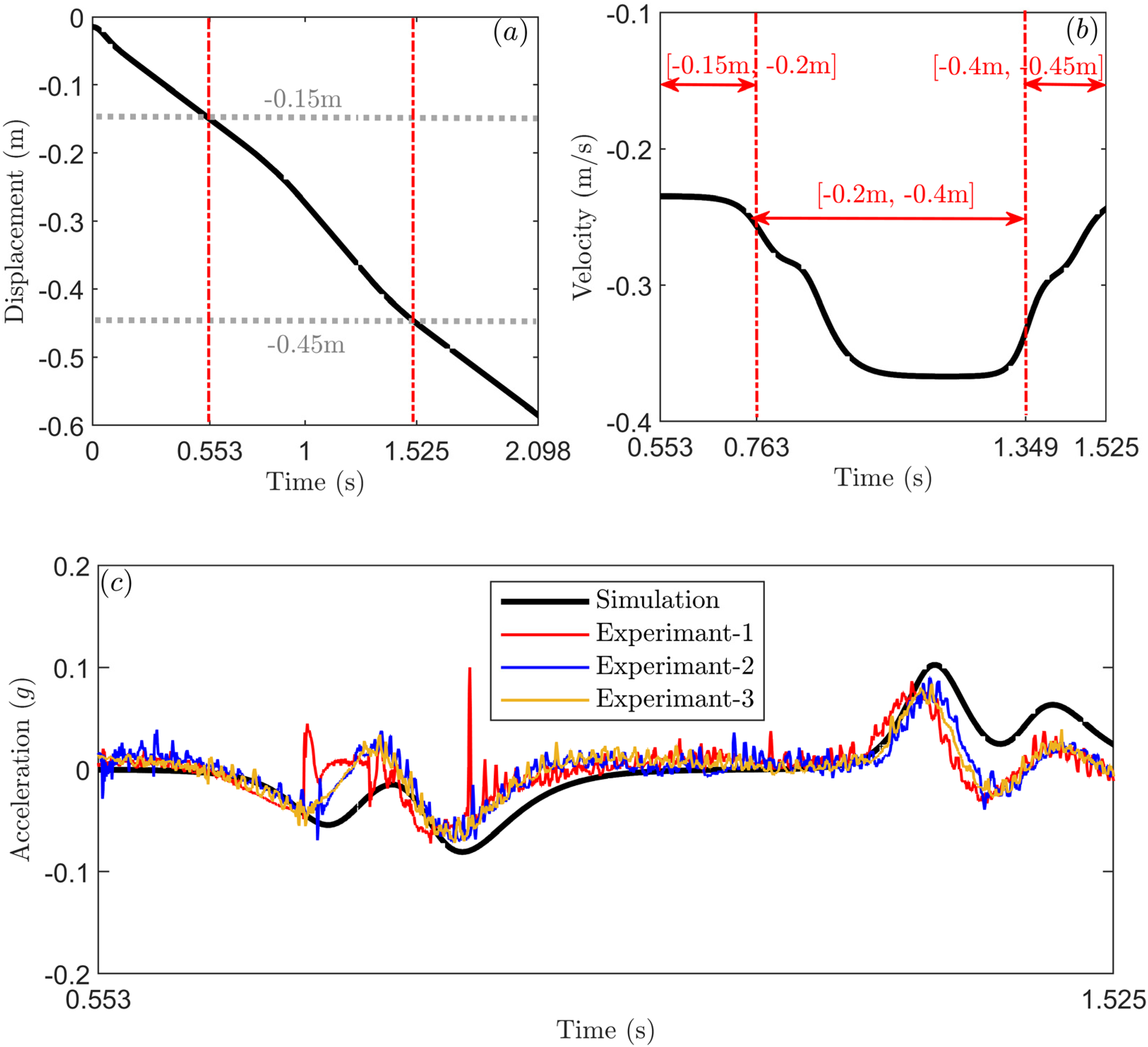
(a) Simulation results of the displacement of magnet A. (b) Simulation results of the velocity of magnet A in the time range of [0.553 s, 1.525 s]. (c) Simulation and experimental results of the acceleration of magnet A in the time range of [0.553 s, 1.525 s]. All black lines in this figure correspond to simulation results of Eq. (21). Colour lines in Figure 9(c) correspond to experimental measured acceleration of magnet A.
The simulation results of the velocity
There are still some errors between the simulation results and the experimental results. The reasons for the errors are as follows:
Firstly, the end of the acceleration sensor is connected to the signal acquisition device by a long special wire for the sensor. As magnet A falls inside the damping tube, the mass of the wire acting on magnet A is increased, resulting in the mass
Secondly, in order to allow magnet A to fall freely, the inner diameter of the PTFE tube is larger than the diameter of magnet A. As a result, magnet A may have small tilts during its fall and may result in random slight collision between magnet A and the tube wall. However, these unpredictable tilts of magnet A are not considered in our calculation model.
Thirdly, although the surface of magnet A is very smooth and the friction coefficient of the PTFE tube is very small, the friction between magnet A and the PTFE tube wall is still unavoidable during the experiment. At the same time, the friction between the wire and the wall of the PTFE tube could also affect the experimental results.
Besides, in the actual situation, the distribution of eddy currents on the surface of the damping tube is non-uniform. The assumption of “eddy currents move only along the conductor plane perpendicular to the axis of the damping tube” in the model derivation process may also be a reason causing some errors.
Dynamic Responses of the TMSDVA with NL-ECD
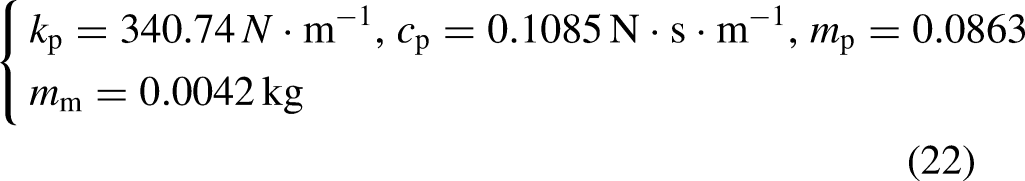
In this part, dynamic responses of the TMSDVA with NL-ECD are analysed to see how NL-ECD affects the vibration reduction performance of the TMSDVA. The parameters of the magnets in the TMSDVA are shown in Table 1 of Appendix B. The magnet distance l is 46 mm. The parameters of the TMSDVA vibration reduction system are shown as follows:
Parameters of Magnets A, B, and C in Section 4.
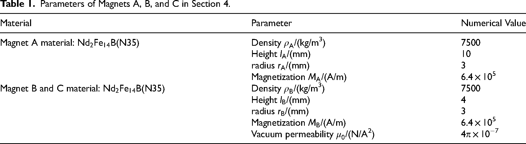
Figure 10(a) shows the magnetic suspension force
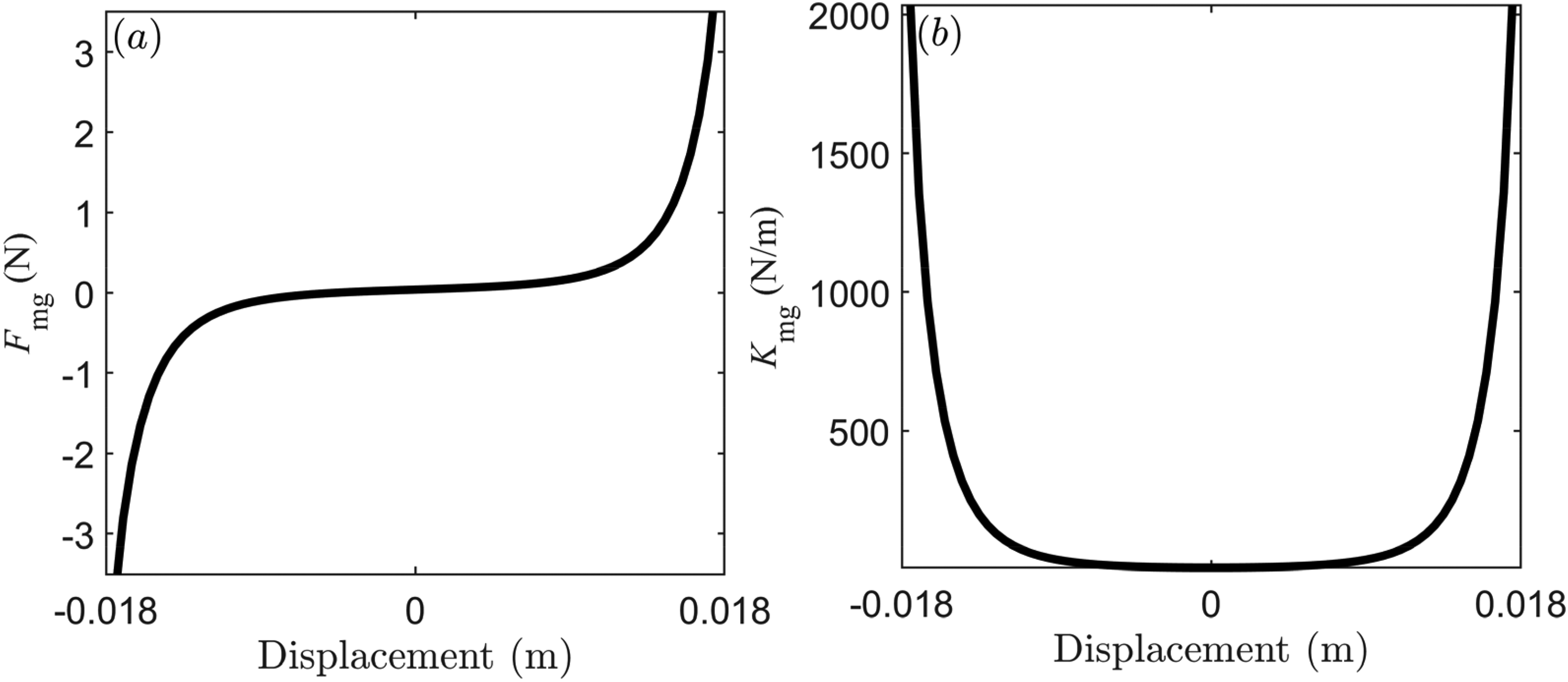
Diagram of (a) the nonlinear magnetic suspension force
Because the magnet distance of the TMSDVA is 46 mm and the height of magnet A is 10 mm, the movement range of magnet A is [-18 mm, 18 mm]. For the TMSDVA shown in Figure 1(a), the inner radius of the linear ECD damping tube D1 is 4 mm, and the outer radius is 5 mm. The length of the damping tube is 60 mm. According to Eq. (19), the ECD coefficient of the TMSDVA in the magnet movement range is always kept constant. In other words, the TMSDVA has linear damping under this parameter condition. After calculation, the value of the linear ECD coefficient
Figure 11(a) depicts the amplitude-frequency response curve of the TMSDVA vibration reduction system when the linear ECD coefficient is about 0.08 Ns/m. From the figure, a higher branch response occurs in the vibration reduction system. The vibration peak value of the primary structure without TMSDVA is approximately 26.3 mm. Due to the large vibration peak value 18.7 mm of the higher branch response in the vibration reduction system, the vibration amplitude of the primary structure is reduced by only 28.90%. In addition to the larger vibration peak of the higher branch response, another smaller vibration peak appears at the frequency of 10.1 Hz. Figure 11(b) plots the time-domain waveform of the system at the frequency of 10.1 Hz. The envelopes of the time-domain waveform shown in Figure 11(b) undergo obvious modulation, which illustrates that modulated responses appear in the vibration reduction system. The peak value of the time-domain waveform is about 4.7 mm.
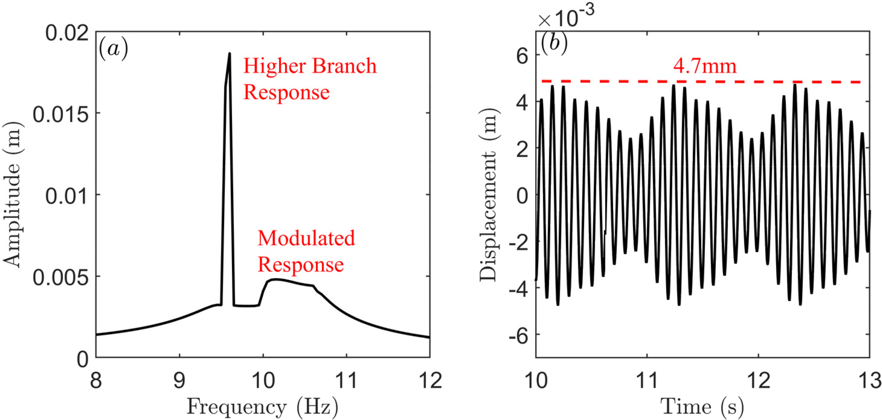
The root-mean-square value of the acceleration amplitude is 0.15 g. The damping of the TMSDVA is linear, and the ECD coefficient is about 0.08 Ns/m. (a) The amplitude-frequency response curve of the TMSDVA vibration reduction system. (b) The time-domain waveform of the TMSDVA vibration reduction system at the frequency of 10.1 Hz.
According to Ref. (Starosvetsky and Gendelman, 2009), increasing the damping coefficient of the TMSDVA is an effective way to eliminate higher branch responses of the system. Hence, we increase the outer radius of the linear ECD damping tube D1 to 7 mm and keep the inner radius unchanged. The linear ECD coefficient is increased to 0.15 Ns/m from 0.08 Ns/m. It should be noted that, to investigate the effect of damping variation on the vibration reduction effect of the TMSDVA, we ignore the variation in the mass of the damping tube. Figure 12(a) shows the amplitude-frequency response curve of the TMSDVA vibration reduction system when the linear ECD coefficient is 0.15 Ns/m. From the figure, no higher branch response occurs in the vibration reduction system anymore. The peak vibration of the response curve appears at the frequency of 9.8 Hz. Figure 12(b) displays the time-domain waveform of the system at the frequency of 9.8 Hz, which illustrates that the system undergoes steady periodic motion. It demonstrates that there is also no modulated response occurring in the vibration reduction system. In this case, the TMSDVA performs like a TMD (Lu et al., 2017). The peak value of the time-domain waveform is about 5.6 mm, which is significantly larger than that shown in Figure 11(b). The vibration amplitude of the primary structure is reduced by 78.71% under these conditions.
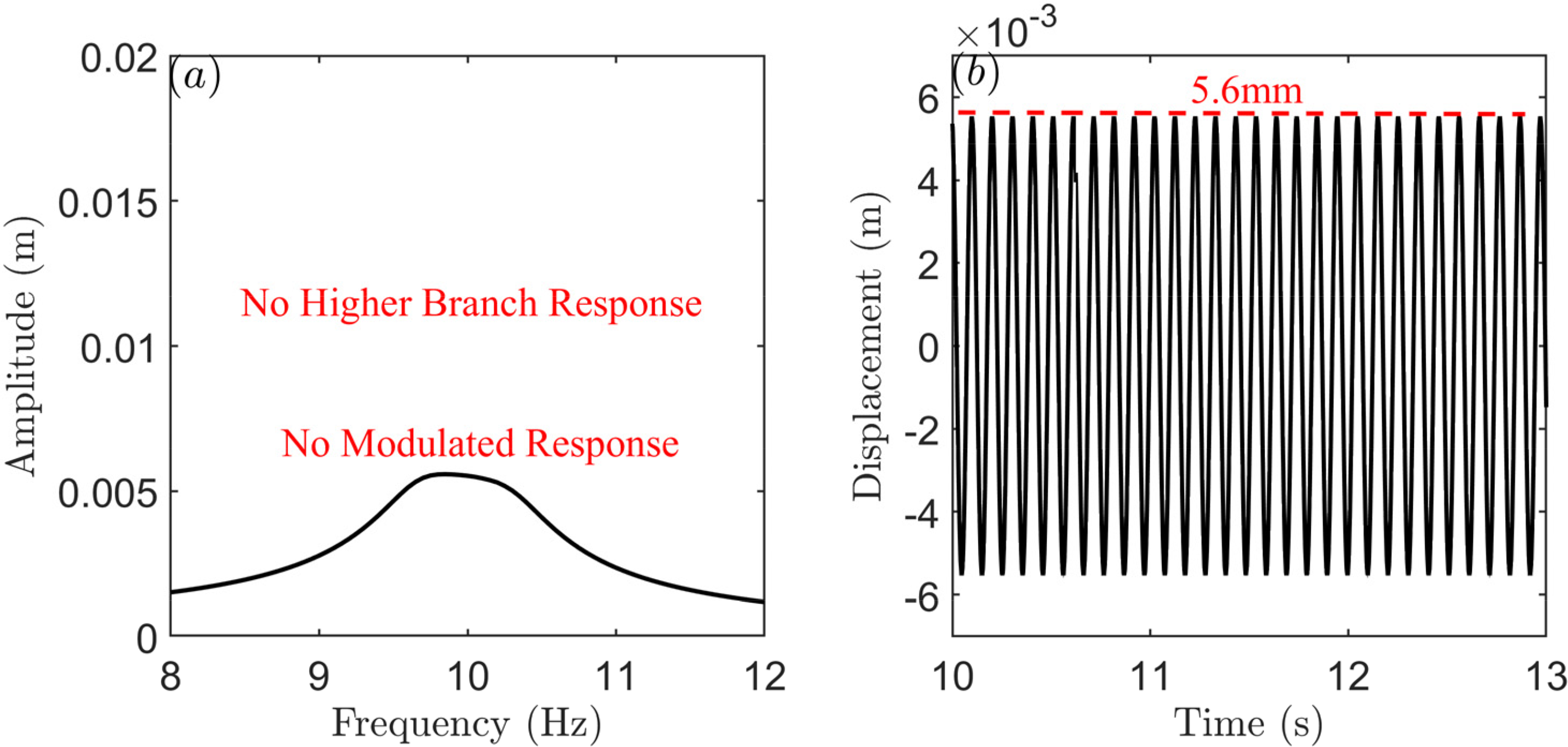
The root-mean-square value of the acceleration amplitude is 0.15 g. The damping of the TMSDVA is linear, and the ECD coefficient is about 0.15 Ns/m. (a) The amplitude-frequency response curve of the TMSDVA vibration reduction system. (b) The time-domain waveform of the TMSDVA vibration reduction system at the frequency of 9.8 Hz.
Although increasing the linear ECD coefficient can eliminate higher branch responses in the vibration reduction system, the modulated responses in the system cannot be retained. According to Ref. (Starosvetsky and Gendelman, 2009), the vibration reduction effect of the TMSDVA can be further improved using NL-ECD instead of linear ECD. Figure 13 shows the schematic diagram of the TMSDVA with NL-ECD. The inner radius of the NL-ECD damping tube D2 is still 4 mm. All three segments (
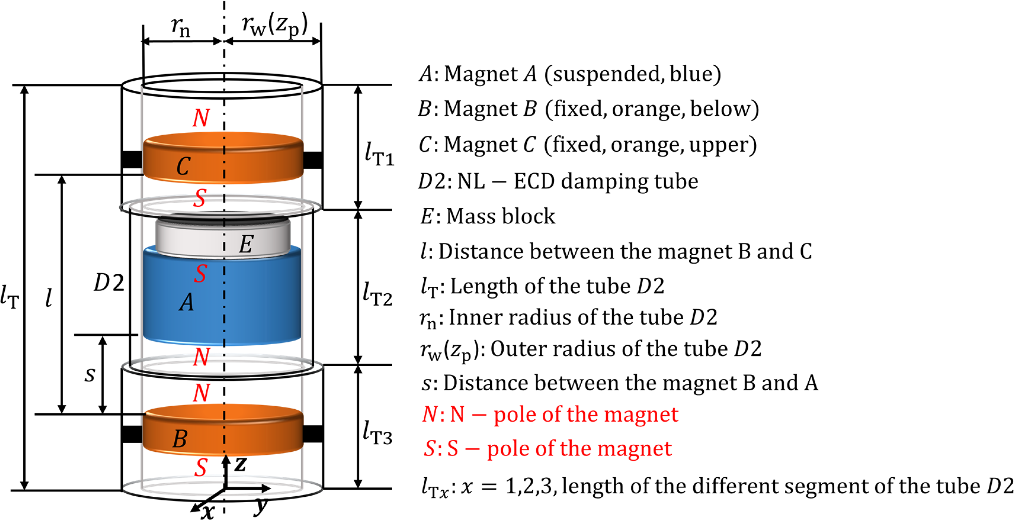
Schematic diagram of the TMSDVA with NL-ECD.
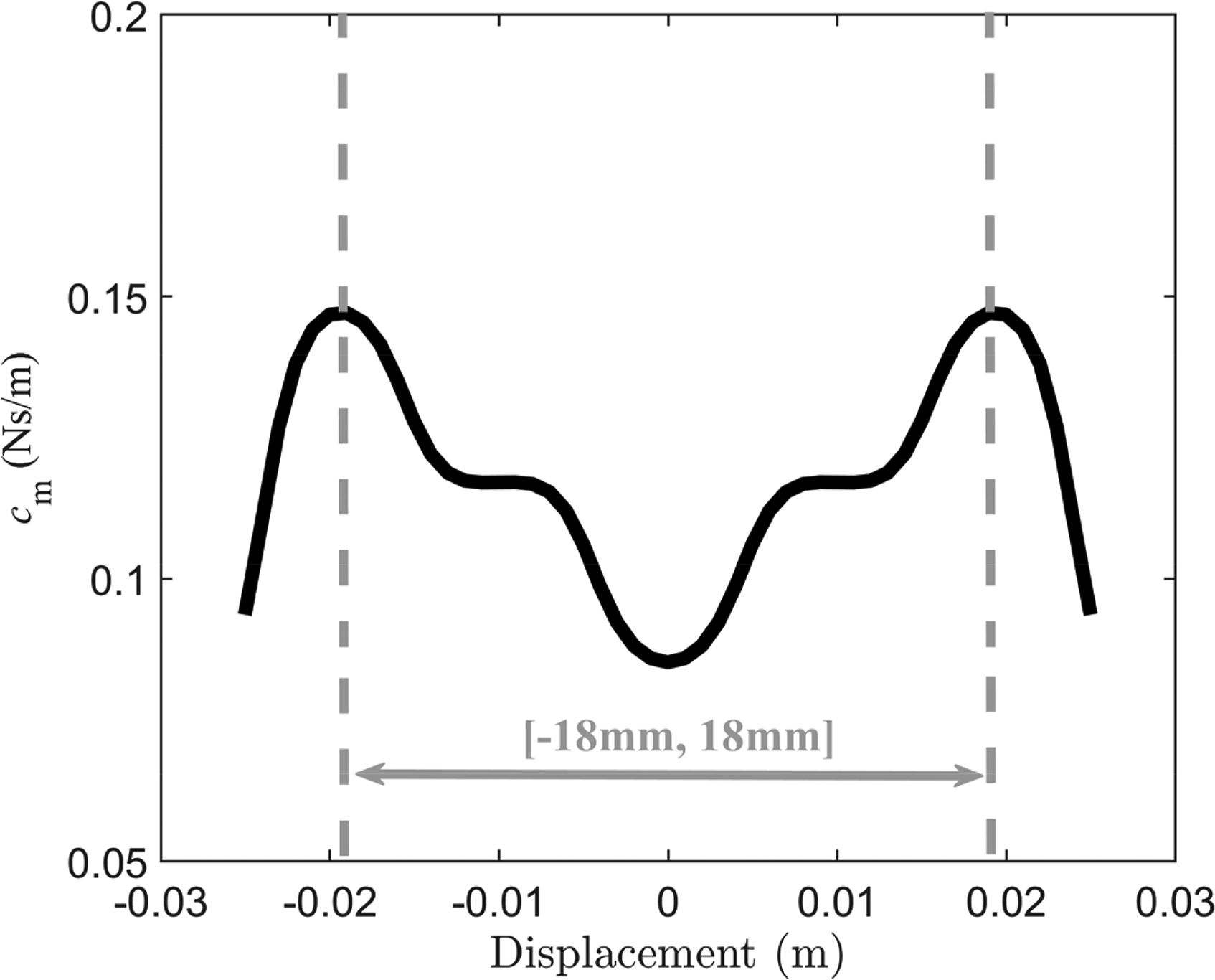
ECD coefficient curve of the TMSDVA.
Figure 15(a) shows the amplitude-frequency response curve of the primary structure with the TMSDVA using NL-ECD. From Figure 15(a), no higher branch response occurs in the vibration reduction system. The peak vibration of the response curve appears at the frequency of 10.25 Hz. Figure 15(b) displays the time-domain waveform of the system at the frequency of 10.25 Hz, which illustrates that the envelopes of the time-domain waveform still undergo modulation in this case. The peak value of the time domain waveform is about 4.7 mm, which is equal to that shown in Figure 11(b). The vibration amplitude of the primary structure is reduced by 82.13%. Therefore, the vibration reduction effect of the TMSDVA with NL-ECD is better than that of the TMSDVA with linear ECD.

The root-mean-square value of the acceleration amplitude is 0.15 g. The NL-ECD coefficients of the TMSDVA are shown in Figure 14. (a) The amplitude-frequency response curve of the TMSDVA vibration reduction system. (b) The time-domain waveform of the TMSDVA vibration reduction system at the frequency of 10.25 Hz.
The above phenomena demonstrate that using NL-ECD can not only eliminate higher branch responses in the TMSDVA vibration reduction system, but also retain the non-linear dynamics response characteristics of the system, leading to a better vibration reduction effect of the TMSDVA.
Conclusion
In this work, a novel Nonlinear Eddy Current Damping (NL-ECD) design method for a Triple-magnet Magnetic Suspension Dynamic Vibration Absorber (TMSDVA) is proposed, modelled, and tested. The NL-ECD coefficient can be designed and adjusted by changing the dimensional parameters of the damping tube. The realization of this method is completely passive and does not require an external energy supply.
From the analysis, the NL-ECD coefficient is strongly related to the position of the moving magnet. Using NL-ECD can not only eliminate higher branch responses in the TMSDVA vibration reduction system, but also retain the non-linear dynamics response characteristics of the system, leading to a better vibration reduction effect of the TMSDVA.
Moreover, the NL-ECD design method proposed in this paper can be applicable to either the TMSDVA or to other types of magnetic DVAs using cylindrical magnets or ring magnets (e.g., the magnetic DVAs in Refs. Benacchio et al., 2016, Yamakawa et al., 1977).
Footnotes
Author Contributions
Funding
The authors disclosed receipt of the following financial support for the research, authorship, and/or publication of this article: This work is supported by the National Natural Science Foundation of China (Grant No. 52275122 and 12132010).
Declaration of Conflicting Interests
The authors declared the following potential conflicts of interest with respect to the research, authorship, and/or publication of this article: We declare that we have no financial and personal relationships with other people or organizations that can inappropriately influence our work, there is no professional or other personal interest of any nature or kind in any product, service and/or company that could be construed as influencing the position presented in, or the review of, the manuscript entitled, “A Novel Nonlinear Eddy Current Damping Design Method for a Triple-magnet Magnetic Suspension Dynamic Vibration Absorber”.
Data Availability
The data that support the findings of this study are available from the corresponding author upon reasonable request.
Appendix A
The detailed derivation of Eqs. (3) to (6) is given below. According to Refs. (Sun et al., 2021; Zhang et al., 2017), for axially magnetised cylindrical permanent magnets, the surface equivalent magnetising current is distributed in a circular shape around the magnetisation axis of the magnet. We take the centre of the circular current loop as the origin and establish a coordinate system as shown in Figure A-1. Then the following relations can be obtained: