
Abstract
A novel Triple-magnet Magnetic Dynamic Vibration Absorber (TMDVA) with Eddy Current Damping (ECD) and Coulomb damping is proposed in this paper. A multi-storey structure is selected as the vibration reduction object. First, the equivalent dynamics model of the TMDVA multi-storey structure vibration reduction system is established. Then the nonlinear magnetic force model is built according to the magnetizing current theory. Next, an ECD accurate calculation model is developed and derived based on Faraday’s law of electromagnetic induction. Because of the model, the ECD coefficient can be designed and adjusted arbitrarily. The full text indicates that adjusting the ECD coefficient properly can not only improve the vibration reduction effect of the TMDVA, but also reduce the sensitivity of the vibration reduction effect to the excitation amplitude as well as enhance the broadband vibration reduction performance and the robustness of the TMDVA. With its simple structure, the TMDVA is easy to be implemented and miniaturized. And the low frequency vibration reduction effect of the TMDVA is better than other existing magnetic dynamic vibration absorbers. Taken together, the TMDVA has potential application value in passive vibration reduction of engineering structures.
Keywords
Highlights
A novel Triple-magnet Magnetic Dynamic Vibration Absorber (TMDVA) with Eddy Current Damping (ECD) and Coulomb damping is proposed in this paper. A more accurate ECD calculation model is derived and established, and the ECD coefficient can be designed and adjusted arbitrarily. Adjusting the ECD coefficient can improve the vibration reduction effect and broaden the tunable frequency range of the TMDVA, and decrease the sensitivity of the vibration reduction effect to the excitation amplitude. The low frequency vibration reduction effect of the TMDVA is better than that of other existing magnetic dynamic vibration absorbers.
Introduction
Structural vibration is ubiquitous in various fields such as aerospace, mechanical and civil engineering. John Milne first proposed the concept of vibration control in the early 19th century [1], and then Yao [2] introduced it into civil engineering in 1972 to study the vibration control of civil structures. In general, from the perspective of energy input, vibration control methods can be divided into three categories: active control, semi-active control and passive control. Heidari et al. [3] have designed and modeled a new active squeeze film damper. And they have also achieved the active vibration control of the rotor-bearing system by a virtual dynamic absorber [4]. And the vibration reduction performance of the absorber is excellent. Active and semi-active control requires external energy input, while passive control does not. Dynamic Vibration Absorber (DVA), a passive vibration reduction device, was first proposed by Frahm in 1909 [5]. DVAs have been widely used in the vibration control of engineering structures. Linear Dynamic Vibration Absorber (LDVA) is also called Tuned Mass Damper (TMD). When the natural frequency of the TMD is approximately equal to the vibration frequency of the primary structure, the TMD can provide the primary structure with a force that is opposite to the excitation force and can dissipate vibration energy through its damping [6,7]. The TMD classical design theory proposed by Den Hartog [8] and Ormondroyd [9] has been widely used in the parameter optimization of TMDs. The H∞ and H2 optimization procedures [10] can also be used to optimize the parameters of the system. Brzeski et al. [11,12] have proposed a novel TMD and studied the damping properties of the proposed TMD for a single-degree-of-freedom simple harmonic forced oscillator. Both the simulation and experimental results have demonstrated that the TMD exhibits a good vibration reduction effect. Liu et al. [13] have established a three-dimensional finite element model with higher reliability after having studied the vibration control performance of an eddy current TMD. It is well known that the vibration reduction effect of TMDs is influenced by the excitation frequency, not the excitation amplitude. When the excitation frequency changes, the vibration reduction effect of TMDs may decrease rapidly. Hence, TMDs have obvious limitations in structural broadband vibration reduction.
With the development of the DVA research, more and more researchers begin to focus on the Nonlinear Dynamic Vibration Absorber (NLDVA). Roberson [14] has indicated that introducing nonlinear stiffness to DVAs can expand the vibration reduction frequency band and enhance the robustness of DVAs. There are many kinds of NLDVAs, such as cubic stiffness NLDVAs [15], piecewise stiffness NLDVAs [16] and tuned stiffness NLDVAs [17], et al. Nonlinear Energy Sink (NES) is a kind of NLDVA that can make the vibration energy targeted transferred to itself from the primary structure and dissipated by the damping. NES has been first proposed and named by Vakakis [18]. NESs distinguish from other NLDVAs because of Targeted Energy Transfer (TET) [19,20], which is fast, unidirectional and irreversible. However, in practical applications, the fabrication process of most NESs is complicated, and it is difficult to achieve accurate nonlinear stiffnesses [21,22], which limits the engineering applications of NESs.
In the studies of NLDVAs, the researchers have also paid attention to the DVA with magnetic properties. The nonlinear stiffness of the magnetic DVA is generated by the interaction between magnets [23,24]. Compared with NLDVAs constructed from non-magnetic components, magnetic DVAs greatly reduce the difficulty of obtaining nonlinear stiffness. Moreover, because there is no contact between magnets, magnetic DVAs are not prone to stiffness degradation; therefore, they enjoy stronger stability and longer service life. Kosuke et al. [25] have proposed an auto-tuned magnetic DVA, which can suppress the higher modal vibrations of the primary structure. And an optimal self-correcting control method that suppresses both fundamental and higher-order modal vibrations has been proposed. Dong et al. [26] have proposed a magnetic NLDVA with negative stiffness. And then they have put forward an iterative algorithm to perform parameter optimization. Wang et al. [27] have proposed a magnetic DVA and conducted theoretical and experimental studies on the properties and performance of the TMD. It has been demonstrated that the magnetic DVA can effectively suppress the low-frequency vibrations of primary structures. Benacchio and Lo Feudo et al. [28,29] have designed a magnetic DVA with tunable stiffnesses using some ring magnet sets and applied it to vibration control of a multi-storey structure. Chen et al. [30] have used some rectangular magnets to design a bistable magnetic DVA suitable for vibration control of a multi-storey structure. Overall, the existing magnetic DVAs usually need a lot of magnets, which makes the structures of the magnetic DVAs complicated. Meanwhile, because of that, the magnetic DVAs, with high installation space requirements, are not conducive to miniaturization. It is difficult for the existing magnetic DVAs to be applied to the vibration reduction of small-sized structures. Recently, research on magnetorheological (MR) gels has also been widely developed. Jang and Kim et al. [31,32] have proposed a novel tunable vibration absorber based on MR gels. Theoretical modeling and experimental validation have been carried out. This vibration absorber requires less input energy and is easy to install. Both simulation and experimental results demonstrate that the tunable frequency range of this vibration absorber can reach 51.6 Hz–71.9 Hz, which is better than that of the traditional TMDs. Therefore, the application of MR gels may be a new research direction in the research field of magnetic DVAs.
Based on the above background, a novel Triple-magnet Magnetic Dynamic Vibration Absorber (TMDVA) with Eddy Current Damping (ECD) [33,34] and Coulomb damping is proposed in this paper. The TMDVA is mainly composed of triple cylindrical permanent magnets and a non-magnetic conductive metal tube (damping tube). The ECD coefficient of the TMDVA can be designed and adjusted arbitrarily by adjusting the dimensional parameters of the damping tube. The TMDVA vibration reduction method does not require external energy input. Due to that, the TMDVA can be installed directly on the primary structure and effectively reduce the vibration of the primary structure. The TMDVA with ECD (EF-TMDVA in this paper) has a wide tunable frequency range. Furthermore, in its tunable frequency range, the vibration reduction effect of the EF-TMDVA will not be affected by the excitation amplitude (input energy) of the system. And the vibration reduction effect of the EF-TMDVA can reach more than 80%. The TMDVA not only can achieve nonlinear vibration reduction, but also can realize linear vibration reduction with the combined effect of the ECD and magnetic quasi-linear stiffness. The TMDVA can be applied to the vibration reduction of structures with horizontal vibration characteristics such as beams, rods and multi-storey structures. With its simple structure, the TMDVA is easy to be implemented and miniaturized. And the low frequency vibration reduction effect is better than other existing magnetic dynamic vibration absorbers.
The paper is organized as follows. In Section 2, a multi-storey structure is selected as the vibration reduction object. And the equivalent dynamics model of the TMDVA multi-storey structure vibration reduction system is established. Based on that, we analyze the characteristics of the nonlinear magnetic force and the ECD. In Section 3, the dynamics equations are solved by using the Runge–Kutta method to analyze the dynamics responses of the TMDVA system with different ECD coefficients. Then the simulation results are verified experimentally in Section 4. In Section 5, the effect of ECD on the tunable frequency range of the TMDVA is discussed. And the advantages and limitations of the TMDVA are also analyzed compared with other DVAs. Section 6 is the conclusion.
Theoretical model
Triple-magnet magnetic dynamic vibration absorber (TMDVA)
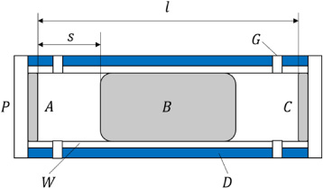
Figure 1 shows the schematic diagram of the TMDVA. A–C are cylindrical permanent magnets. Both the A and C are fixed magnets. The magnet B repels not only the magnet A, but also the magnet C. Accordingly, the magnet B can move along the horizontal direction in the TMDVA. D is a non-magnetic conductive metal tube. For descriptive convenience, we named it damping tube. When the magnet B moves relative to the damping tube D, eddy currents are generated on the surface of the tube, which provides ECD for the TMDVA. The ECD coefficient of the TMDVA can be designed and adjusted arbitrarily by changing the dimensional parameters of the damping tube D. If the magnet B is in direct contact with the damping tube D, the magnet B will be subject to a large friction force. It will not only affect the movement of the magnet B, but also cause the wear of the magnet B and the damping tube D, which will seriously reduce the service life of the TMDVA. Therefore, it is necessary to attach a polytetrafluoroethylene (PTFE) tube W inside the wall of the tube D. The friction coefficient of the PTFE tube is very small, which greatly reduces the wear caused by direct contact between the magnet B and the damping tube D. When the TMDVA is equipped with both the damping tube D and the PTFE tube W, the vibration energy can be dissipated by ECD and Coulomb damping at the same time. Hence, the TMDVA is a dynamic vibration absorber with hybrid damping. In this paper, the Coulomb damping coefficient, which is assumed as a constant value, is not discussed. And the focus of this paper is the influence of the ECD on the vibration reduction effect of the TMDVA.
l in Fig. 1 is the distance between the two fixed magnets. s is the distance between the magnet B and the magnet A. When the magnet B is excited to move, s changes accordingly. P is a magnet base to facilitate fixing the magnet A or C to the tube D and the tube W. G is an air hole to keep the internal air pressure of the TMDVA in line with the external air pressure.
Schematic diagram of the TMDVA.
Figure 2(a) reports the physical map of the multi-storey structure. H is a fixed base that can be fixed to the vibrator in experiments. The vibration direction of the multi-storey structure is along the x-direction. Figure 2(b) displays the schematic diagram of the TMDVA multi-storey structure vibration reduction system. Q is the gripper fixed to the second floor. The TMDVA can be fixed on the second floor of the multi-storey structure through the gripper. l z is the length of the supporting beams. And l z of the first floor is the same as that of the second floor.
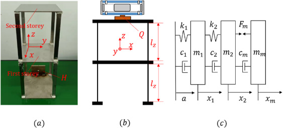
(a) Physical map of the multi-storey structure. (b) Schematic diagram of the TMDVA multi-storey structure vibration reduction system. (c) Equivalent dynamics model of the TMDVA multi-storey structure vibration reduction system.
Figure 2(c) depicts the equivalent dynamics model of the vibration reduction system. According to Newton’s second law, the dynamics equations can be written as:
In Eq. (1), k
1, c
1 and m
1 are the equivalent stiffness coefficient, the equivalent damping coefficient and the equivalent mass of the first floor of the multi-storey structure, respectively. a is the excitation acceleration. F
m
is the nonlinear magnetic force. m
m
is the mass of the magnet B. c
m
is the ECD coefficient of the TMDVA. x
1, x
2 and x
m
are the displacement of the first floor, the second floor and the magnet B relative to the base, respectively. k
2 and c
2 are the equivalent stiffness coefficient and the equivalent damping coefficient of the second floor of the multi-storey structure, respectively. Because the TMDVA is attached to the second floor of the multi-storey structure, m
2 should be calculated as:
In formula (2), m s is the equivalent mass of the second floor of the multi-storey structure. m Q is the mass of the gripper Q. m f is the mass of the fixed magnets A and C. m PTFE is the mass of the PTFE tube W. m ECD is the mass of the damping tube D. And m b is the mass of the magnet base P. For the multi-storey structure without TMDVA, m 2 is equal to (m s + m Q ).
The friction force between the magnet B and the PTFE tube is not considered in Eq. (1). In addition, when the multi-storey structure is vibrating, its gravity will also affect its horizontal vibration. And the greater the bending of the supporting beams is, the greater the effect of the multi-storey structure’s gravity is. Therefore, we modify Eq. (1) based on the friction and deflection calculation equations. And the modified dynamics model is given by:
In Eq. (3), E is the Young’s Modulus of the supporting beams. I
1 and I
2 are the equivalent moments of inertia of the first-floor supporting beams and the second-floor supporting beams, respectively. g is the gravitational acceleration and its value is 9.8 m/s2. μ is the friction coefficient.
The calculation model of the nonlinear magnetic force F
m
is established based on the equivalent magnetizing current theory [23,24]. The magnetic induction
In Eq. (5), r = ((x − r
A
cosθ)2 + (y − r
A
sinθ)2 − (z − z
1)2)1∕2. l
A
and r
A
are the height and radius of the magnet A, respectively. μ0 is the vacuum magnetic permeability. M
A
is the magnetization of the magnet A. The magnetic induction of the magnet C is the same as that of the magnet A. Let
The nonlinear magnetic force F
m
on the multi-storey structure can be expressed as:
The energy of the multi-storey structure vibration reduction system can be calculated by the following formulas:
In formulas (9)–(20), T, V and C represent the kinetic energy, the potential energy and the energy dissipated by the damping, respectively. Formulas (9)–(11) correspond to the energy of the first floor of the multi-storey structure, and formulas (12)–(14) that of the second floor of the multi-storey structure. Formulas (15)–(18) correspond to the energy of the TMDVA. Formulas (19) and (20) are the potential energy of the system caused by the bending of the supporting beams.
According to the law of energy conservation, the total energy W
t
of the system can be calculated as:
Then we let
Here in formula (22), E DISS , % represents the percentage of the total energy dissipated in the TMDVA. The larger the E DISS , % is, the more energy dissipated in the TMDVA is.
Table 1 presents the parameters of the magnets. According to Table 1 and Eq. (7), Fig. 3 displays the nonlinear magnetic force F m . The magnet distance l is 100 mm. The figure demonstrates that approximately within the interval [−12 mm, 12 mm], the variation of the stiffness is very small. Hence, as an approximation, we consider that the force F m has a quasi-linear stiffness feature. When the displacement is out of the interval, the slope of the nonlinear magnetic force changes significantly, showing obvious nonlinear characteristics.
Parameters of the magnets in the TMDVA
Parameters of the magnets in the TMDVA
In order to further understand the characteristics of the nonlinear magnetic force, the polynomial fitting formula of the force F
m
(RMSE is approximately 1.68%), can be expressed as:
When the displacement of the magnet B is small, the linear force 27.86 × (x m − x c ) in formula ((23)) plays a key role. This means the variation of the slope is very small. After calculation, the slope of the nonlinear magnetic force in the interval [−12 mm, 12 mm] is approximately equal to the linear term coefficient 27.86 N/m in formula ((23)). The displacement of the magnet B is affected by both the ECD coefficient and the excitation amplitude. The ECD is viscous and it can dissipate the motion energy of the magnet B. Therefore, when the ECD coefficient is large, the vibration energy in the TMDVA will be dissipated fast through the large ECD. Due to that, the displacement of the magnet B becomes very small. The motion range of the magnet B is in the quasi-linear interval of the magnetic force. The vibration reduction system will not be affected by the nonlinear factors of the magnetic force. Hence, the response of the system is linear. On the contrary, when the ECD coefficient is small, the vibration energy in the TMDVA cannot be dissipated fast. Therefore, the displacement range of the magnet B will become very large when the excitation amplitude is larger than a certain value. The vibration reduction system will be strongly affected by the nonlinear stiffness of the magnetic force. And the dynamic response of the system is nonlinear. This feature of the TMDVA will be discussed in detail in Section 5 in conjunction with the simulation and experimental results.

Nonlinear magnetic force.
Because of the structural features of the TMDVA, the damping of the TMDVA is a kind of cylindrical magnetic ECD. The dampers with ECD have been widely used in the vibration control of engineering equipment, but there is still a lack of reliable and practical theoretical ECD calculation models to guide engineering design. Reference [34] has proposed a theoretical model of ECD based on the electromagnetic eddy current theory. But in order to reduce the computational complexity, the authors approximated the radial magnetic induction of the permanent magnet as a constant, which made the results inaccurate. In this section, based on Faraday’s law of electromagnetic induction, we re-derived a more accurate calculation formula for the ECD coefficient, which is different from that of Ref. [34]. The derivation of the formula is easier to be understood for readers.
Figure 4 shows the equivalent calculation model of the ECD. We equate the damping tube to a coil with the same material so that the direction of the induced current can only be along the wire, i.e., the plane of the eddy current motion is perpendicular to the z-direction. When the magnet B moves along the direction of the z-axis, the direction of the induced current is shown in the direction of i in Fig. 4.

Equivalent calculation model of the eddy current damping (ECD).
Accordingly, the induction electromotive force ΔE in the Δz section can be expressed as:
v is the movement velocity of the magnet B. L is the equivalent perimeter of the damping tube, and the formula can be written as:
r is the median diameter of the damping tube. r
n
and r
w
are the inner radius and the outer radius of the damping tube, respectively. The formula of the equivalent resistance R
Δz
of the damping tube is given by:
In formula (27), 𝜌 is the resistivity of the damping tube. Take an aluminum tube as an example, the resistivity of the aluminum tube is 2.85 × 10⁻⁸ Ω/m. Then the current Δi in the Δz section is:
And the force of the N pole of the magnet B on the Δz section of the damping tube is:
Then the N-pole force of the magnet B on the entire damping tube can be expressed as:
The equation of the S-pole force of the magnet B on the entire damping tube is the same as that of the N-pole force. Therefore, the entire damping force on the damping tube is:
Formula (31) shows that F
c
is proportional to v, which indicates that the ECD damping force is a kind of linear viscous damping force. Because of that, the ECD damping coefficient c
m
can be obtained as:
We divide the interval [r
n
, r
w
] into small intervals of equal length with (r
w
− r
n
)∕p. The values in the interval are r
n,0(r
n
), r
n,1, r
n,2, …, r
n, p−2, r
n, p−1, r
n, p
(r
w
). Substituting those values into formula (33), we get B
i,0…B
i, p
. The root mean square value B
iRMS
of B
i
can be calculated by formula (34):
Finally, the calculation formula of the ECD coefficient is given by:
The ECD coefficient can be adjusted by changing the parameters of the damping tube. The parameters of the magnet B are the same as those in Table 1. The material of the damping tube is aluminum. The length l t of the tube is 1000 mm. Figure 5(a) indicates that, when the inner radius r n is kept constant, as the thickness Δr of the damping tube increases, the ECD coefficient c m increases monotonically. But the slope of the c m −Δr curve decreases gradually, which is affected by the distribution characteristics of the magnetic induction intensity B i [23,24]. Similarly, as shown in Fig. 5(a), when the thickness of the damping tube is kept constant, changing the inner radius of the damping tube can also affect the ECD coefficient. The smaller the inner radius is, the larger the ECD coefficient is.
According to formula (35), the ECD coefficient can also be influenced by the length of the damping tube. The thickness and the inner radius of the damping tube are kept at 1 mm and 26 mm, respectively. Figure 5(b) demonstrates that the ECD coefficient first increased and then gradually moved towards a constant value as the length of the damping tube increased, which is influenced by the distribution characteristics of the magnetic induction intensity B i as well. The farther the distance from the magnet B is, the weaker the magnetic induction intensity produced by the magnet B is. Therefore, increasing the length of the damping tube cannot affect the ECD coefficient when the length of the damping tube is larger than a certain value.
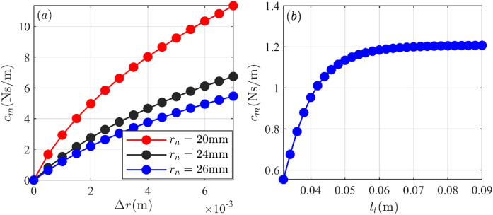
(a) Change of the ECD coefficient influenced by the thickness and the inner radius of the damping tube. (b) Change of the ECD coefficient influenced by the length of the damping tube.
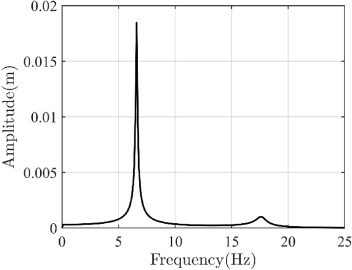
Table 2 shows the parameters of the multi-storey structure vibration reduction system. The amplitude frequency response curve of the second floor of the multi-storey structure without TMDVA is depicted in Fig. 6. And the sinusoidal excitation amplitude is 0.1 g. The first resonance frequency of the structure is 6.6 Hz, and the second resonance frequency is 17.6 Hz. The vibration amplitude of the structure at the frequency of 6.6 Hz is much larger than that at the frequency of 17.6 Hz. Therefore, our study focuses on the vibration reduction effect of the TMDVA at the first resonance frequency of the multi-storey structure.
Let the peak value of the amplitude frequency curve of the multi-storey structure without the TMDVA be max(AF
MS
), and the peak value of the amplitude frequency curve of the multi-storey structure with the TMDVA be max(AF
MS−TMDV A
). We introduce an index RE, % to evaluate the vibration reduction effect of the TMDVA:
The larger the RE, % is, the better the vibration reduction effect of the TMDVA is.
Parameters of multi-storey structure vibration reduction system
Amplitude frequency response curve of the second floor of the multi-storey structure without TMDVA.
When the TMDVA has different ECD coefficients, the influence of the excitation amplitude on the vibration reduction effect of the TMDVA is reported in Fig. 7. The figure illustrates that the vibration reduction effect of the TMDVA has a strong sensitivity to the excitation amplitude when the ECD coefficient is small. That is, the vibration reduction effect of the TMDVA varies obviously with the excitation amplitude. However, when c m is larger than 0.5 Ns/m, all the vibration reduction effects of the TMDVA can reach more than 80% and are hardly affected by the excitation amplitude. It is found that adjusting the ECD coefficient properly is necessary, which can not only improve the vibration reduction effect of the TMDVA, but also reduce the sensitivity of the TMDVA vibration reduction effect to the excitation amplitude.
Based on the above results, two TMDVAs with ECD coefficients of 0 Ns/m and 1.21 Ns/m respectively are selected for analysis. When c m = 0 Ns/m, the TMDVA can only dissipate energy through the friction (Coulomb) damping. For the sake of description, we named it F-TMDVA. When c m = 1.21 Ns/m, the TMDVA can dissipate energy through the friction (Coulomb) damping and the ECD, and we named it EF-TMDVA. The PTFE tube and the damping tube are both 100 mm long. The inner radius and the outer radius of the PTFE tube are 21 mm and 25 mm, respectively. The inner radius and the outer radius of the damping tube are 26 mm and 28 mm, respectively. According to the formula (2), m 2 = 0.2755 Kg is for the F-TMDVA multi-storey structure vibration reduction system, and m 2 = 0.2993 Kg is for the EF-TMDVA vibration reduction system.
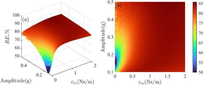
When the TMDVA has different ECD coefficients, the influence of the excitation amplitude on the vibration reduction effect of the TMDVA. (a) Three dimensional map. (b) Cloud map.
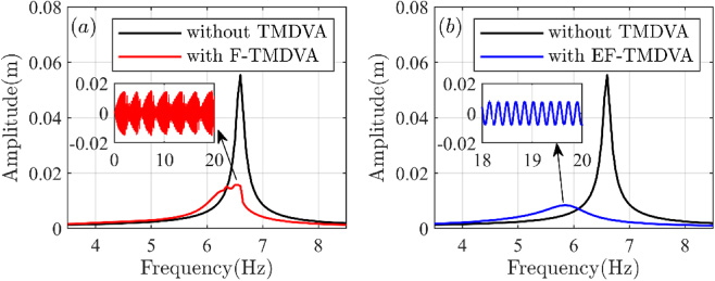
Figure 8 depicts the amplitude frequency response curves of the multi-storey structure vibration reduction system when the excitation amplitude is 0.1 g. Figure 8(a) illustrates that the resonance frequency f F of the multi-storey structure with the F-TMDVA is 6.35 Hz. And the displacement peak is 9.04 mm. Figure 8(b) demonstrates that the resonance frequency f EF of the multi-storey structure with the EF-TMDVA is 5.7 Hz. And the displacement peak is 3.11 mm. The displacement peak of the multi-storey structure without TMDVA is 18.46 mm. Based on the results, the vibration reduction effect of the F-TMDVA and the EF-TMDVA is 51.03% and 83.15%, respectively. Therefore, the vibration reduction effect of the EF-TMDVA is better than that of the F-TMDVA.
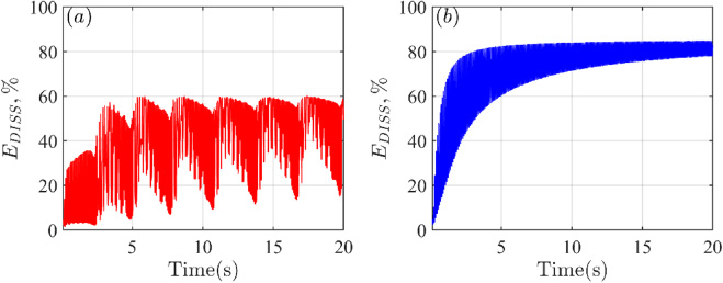
From Fig. 8, both the two systems perform periodic sinusoidal motion. Figure 9 reports the percentage of the total energy dissipated in the TMDVA. Figure 9(a) demonstrates that the E DISS , % of the F-TMDVA is approximately 50.95% when the system reaches the steady state. Figure 9(b) indicates that the E DISS , % of the EF-TMDVA is approximately 82.95% when the system reaches the steady state. Compared with the F-TMDVA, the EF-TMDVA can dissipate more vibration energy through its large damping, which makes the vibration reduction effect of the EF-TMDVA significantly better than that of the F-TMDVA.
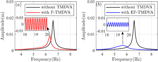
Amplitude frequency response curves of the multi-storey structure vibration reduction system when the excitation amplitude is 0.1 g. (a) F-TMDVA. (b)EF-TMDVA.
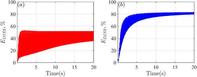
The percentage of the total energy dissipated in the TMDVA when the excitation amplitude is 0.1 g. (a) F-TMDVA, f F = 6.35 Hz. (b) EF-TMDVA, f EF = 5.7 Hz.
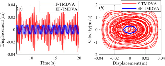
Figure 10 depicts the motion state of the magnet B in the TMDVA. The figure presents that the magnet B in the F-TMDVA performs periodic sinusoidal motion. The displacement amplitude of the magnet B in the F-TMDVA is approximately 11.2 mm. And the figure shows that the magnet B in the EF-TMDVA also performs periodic sinusoidal motion. And the displacement amplitude of the magnet B in the EF-TMDVA is about 2.3 mm, which is much smaller than that of the magnet B in the F-TMDVA. From Fig. 9(b) we can conjecture that the smaller displacement and velocity of the magnet B in the EF-TMDVA is because the large damping results in the faster decay of the response. As soon as vibration energy is transferred to the EF-TMDVA, it is almost immediately dissipated by the large damping.
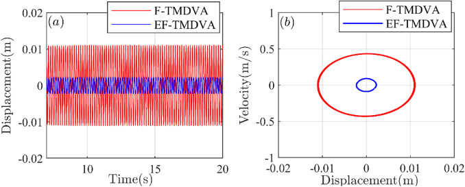
Time-domain waveforms (a) and phase diagrams (b) of the magnet B when the excitation amplitude is 0.1 g.
We increase the excitation amplitude to 0.3 g. Figure 11 displays the amplitude frequency response curves of the multi-storey structure vibration reduction system. Figure 11(a) demonstrates that the F-TMDVA vibration reduction system exhibits Strongly Modulated Response (SMR) [19] region in the 6.2 Hz–6.6 Hz. And the displacement peak is 15.1 mm, which appears at the frequency f F = 6.6 Hz. Figure 11(b) indicates that the resonance frequency f EF of the multi-storey structure with the EF-TMDVA is still 5.7 Hz. And the displacement peak is 8.4 mm. From Fig. 11, the displacement peak of the multi-structure without TMDVA is about 55.3 mm. Hence, the vibration reduction effect of the F-TMDVA and the EF-TMDVA is 72.69% and 84.81%, respectively. The vibration reduction effect of the EF-TMDVA is still better than that of the F-TMDVA. However, compared with the situation when the excitation amplitude is 0.1 g, the vibration reduction effect of the F-TMDVA is obviously increased as the excitation amplitude increases, but the vibration reduction effect of the EF-TMDVA is not.
Amplitude frequency response curves of the multi-storey structure vibration reduction system when the excitation amplitude is 0.3 g. (a) F-TMDVA. (b) EF-TMDVA.
Figure 11(a) also presents that the nonlinear beat phenomenon occurs in the F-TMDVA system, which provides further evidence for the SMR. From Fig. 11(b), the system with the EF-TMDVA still performs periodic sinusoidal motion. Figure 12 reports the percentage of the total energy dissipated in the TMDVA. Figure 12(a) illustrates that the E DISS , % of the F-TMDVA is approximately 60.05% when the system reaches the steady state, which is much larger than that when the excitation amplitude is 0.1 g. Because of that, the vibration reduction effect of the F-TMDVA is obviously increased as the excitation amplitude increases. Figure 12(b) indicates that the E DISS , % of the EF-TMDVA is approximately 84.37% when the system reaches the steady state, which is not obviously changed compared with Fig. 9(b). And the vibration reduction effect of the EF-TMDVA is almost constant because of that.
The percentage of the total energy dissipated in the TMDVA when the excitation amplitude is 0.3 g. (a) F-TMDVA, f F = 6.6 Hz. (b) EF-TMDVA, f EF = 5.7 Hz.
Figure 13 shows the motion state of the magnet B in the TMDVA when the excitation amplitude is 0.3 g. The figure illustrates that the magnet B in the F-TMDVA exhibits nonlinear beat phenomenon. The displacement amplitude of the magnet B is about 34.3 mm. And the figure also demonstrates that the magnet B in the EF-TMDVA still performs periodic sinusoidal motion. The displacement amplitude of the magnet B is approximately 7.8 mm, which is still much smaller than that of the magnet B in the F-TMDVA because of the large damping.
Time-domain waveforms (a) and phase diagrams (b) of the magnet B when the excitation amplitude is 0.3 g.
Eddy current damping (ECD) measurement experiment
A long enough aluminum tube is placed vertically. Then the magnet is placed vertically from the top of the tube so that the magnet can fall freely in the tube. The magnet can undergo uniform motion inside the aluminum tube under the effect of gravity together with the ECD force. Based on the length of the aluminum tube and the movement time of the magnet, the movement velocity v of the magnet can be calculated approximately. Then the ECD coefficient can be given by:
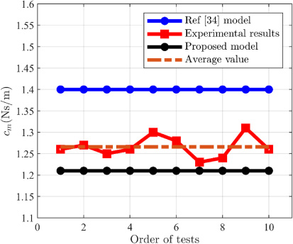
In formula (37), m m is the mass of the magnet. The parameters of the magnet are the same as those of the magnet B depicted in Table 1. The inner radius, outer radius and length of the aluminum tube are 26 mm, 28 mm and 1000 mm, respectively. The ECD measurement experiments were repeated 10 times. Figure 14 shows experimental results and simulation results of the ECD coefficients. The calculated ECD coefficient based on the proposed model in this paper is about 1.21 Ns/m. The calculated coefficient based on the model in Ref. [34] is 1.41 Ns/m. And the average value of the experimental results is 1.26 Ns/m. The errors of the two models are 3.97% and 11.90%, respectively, which indicates that the ECD model proposed in this paper is more accurate than the model in Ref. [34].
Experimental results and simulation results of the ECD coefficients.
For the model proposed in this paper, the simulation result is slightly smaller than the experimental result. One of the reasons for the error is that the motion velocity of the magnet in the aluminum tube is not always uniform. In the initial stage, the magnet needs to undergo a period of accelerated motion. Only when the velocity of the magnet reaches a certain value, can the ECD force is equal to the magnet’s gravity. At this time, the magnet can begin to move at a uniform velocity. Another reason is the friction between the magnet and the aluminum tube. Given all that, the calculated velocity value v is smaller than the true velocity of the magnet in experiments, which leads to the error between the simulation result and the experimental result.
Figure 15 displays the experimental dynamic response measurement system. The excitation signal generated by the signal generator is input into the vibrator through the power amplifier, and the vibrator excites the TMDVA multi-storey structure vibration reduction system. The acceleration sensor 1 is used for acquiring the excitation acceleration a. The acceleration sensor 2 is used for acquiring the acceleration response a 2 of the second floor of the multi-storey structure. Then all the above data can be input into the computer through the signal acquisition device. The experimental parameters of the multi-storey structure are shown in Table 3.
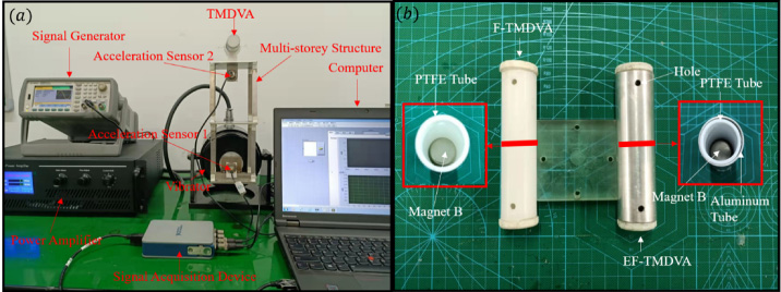
(a) Experimental dynamic response measurement system. (b) TMDVA in experiment.
Experimental parameters of the multi-storey structure
Figure 15(b) depicts the experimental structures of the F-TMDVA and the EF-TMDVA. The parameters of the TMDVAs are the same as those in the simulation. Figure 16 depicts the experimental amplitude frequency response curves of the multi-storey structure vibration reduction system when the excitation amplitude is 0.1 g. From the figure, the resonance frequency of the multi-storey structure without TMDVA is 6.7 Hz, and the acceleration response peak is 3.28 g. Figure 16(a) presents that the resonance frequency f F of the multi-storey structure with the F-TMDVA is 6.4 Hz. And the acceleration response peak is 1.52 g. Figure 16(b) illustrates that the resonance frequency f EF of the multi-storey structure with the EF-TMDVA is 6 Hz. And the acceleration response peak is 0.53 g. The vibration reduction effect of the F-TMDVA and the EF-TMDVA are 53.7% and 83.8%, respectively. The vibration reduction effect of the EF-TMDVA is better than that of the F-TMDVA. Figure 16 also indicates that the systems all perform periodic sinusoidal motion approximately.
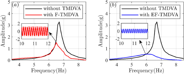
Experimental amplitude frequency response curves of the multi-storey structure vibration reduction system when the excitation amplitude is 0.1 g. (a) F-TMDVA. (b) EF-TMDVA.
Figure 17 shows the experimental amplitude frequency response curves of the multi-storey structure vibration reduction system when the excitation amplitude is 0.3 g. From the figure, the acceleration response peak of the multi-storey structure without TMDVA is 10.12 g. Figure 17(a) illustrates that the F-TMDVA vibration reduction system exhibits SMR in 6.4 Hz–7.2 Hz. And the acceleration response peak is 2.37 g, which appears at the frequency f F = 6.8 Hz. The vibration reduction effect of the F-TMDVA is 72.69%. Figure 17(b) demonstrates that the resonance frequency f EF of the multi-storey structure with the EF-TMDVA is still 6 Hz. And the acceleration response peak is 1.61 g. The vibration reduction effect of the EF-TMDVA is 84.81%. The vibration reduction effect of the EF-TMDVA is still better than that of the F-TMDVA. Taken together, both the experimental results and the simulation results show the same trend, which verifies the correctness of the theoretical analysis in Section 3.

Experimental amplitude frequency response curves of the multi-storey structure vibration reduction system when the excitation amplitude is 0.3 g. (a) F-TMDVA. (b) EF-TMDVA.
From the experimental and simulation results, we find when the excitation amplitude is increased to 0.3 g, the response of the F-TMDVA vibration reduction system exhibits nonlinear dynamics characteristics. The reason is found through the comparison of the displacement of the magnet B and the characteristics of nonlinear magnetic force. When the excitation amplitude is 0.1 g, the movement range of the magnet B in the F-TMDVA is [−11.2 mm, 11.2 mm]. Given the characteristics of the magnetic force, the magnetic force can be approximated as a quasi-linear force in this interval, as depicted in Fig. 18(a). Hence, the F-TMDVA vibration reduction system performs periodic sinusoidal motion approximately when the excitation amplitude is 0.1 g. However, the movement range of the magnet B in the F-TMDVA is [−34.3 mm, 34.3 mm] when the excitation amplitude is increased to 0.3 g. As shown in Fig. 18(a), the movement range of the magnet B covers almost the entire nonlinear magnetic force curve. Due to that, the response of the F-TMDVA vibration reduction system exhibits multi-frequency nonlinear dynamics characteristics (nonlinear beat phenomenon) under the condition.
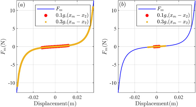
Comparison of the displacement of the magnet B (x m − x 2) and the nonlinear magnetic force F m . (a) F-TMDVA. (b) EF-TMDVA.
From Fig. 18(b), the movement range of the magnet B in the EF-TMDVA is always located in the quasi-linear interval of the magnetic force for both excitation amplitudes 0.1 g and 0.3 g, so that the system performs periodic sinusoidal motion all the time. As soon as energy is transferred to the EF-TMDVA, it is almost immediately dissipated by the large damping, which leads to small kinetic and potential energy of the magnet B. The system can hardly be affected by the nonlinear characteristics of the magnetic force F
m
. From another perspective, the ECD is essentially a linear viscous damping. When the ECD coefficient
In order to analyze the effect of the ECD on the tunable frequency range of the TMDVA, we change the stiffness of the multi-storey structure and keep the other parameters unchanged so that the multi-storey structure can have different natural frequencies. Figure 19 demonstrates that the TMDVA can reduce the vibration of the multi-storey structures with different natural frequencies. From Fig. 19, the tunable frequency range of the F-TMDVA is about 3.14 Hz–11.72 Hz, and the tunable frequency range of the EF-TMDVA is 3.14 Hz–33.11 Hz. In the Ref. [31], the tunable frequency range of the MR tunable vibration absorber is about 51.6 Hz–71.9 Hz, which is larger than the tunable frequency range of the F-TMDVA and smaller than that of the EF-TMDVA. However, the tunable frequency of the MR tunable vibration absorber is higher than that of the TMDVA.
It is worth noting that, the TMDVA is a kind of passive dynamic vibration absorber, which does not need external energy input. Due to that, the TMDVA can be installed directly on the primary structure and effectively reduce the vibration of the primary structure. However, in our study, the vibration reduction performance of the F-TMDVA strongly depends on the excitation amplitude (input energy) of the system. It is the drawback of NLDVAs. That is, the NLDVA can suppress the vibration of the primary structure only when the input energy reaches a certain threshold [19]. This leads to the limitation of the F-TMDVA in engineering applications. In contrast, the vibration reduction effect of the EF-TMDVA can reach more than 80% in the EF-TMDVA’s tunable frequency band of 3.14 Hz–33.11 Hz, even when the input energy is small (e.g., the excitation amplitude is 0.1 g). Therefore, compared with the F-TMDVA, the EF-TMDVA is easier to be applied in engineering.
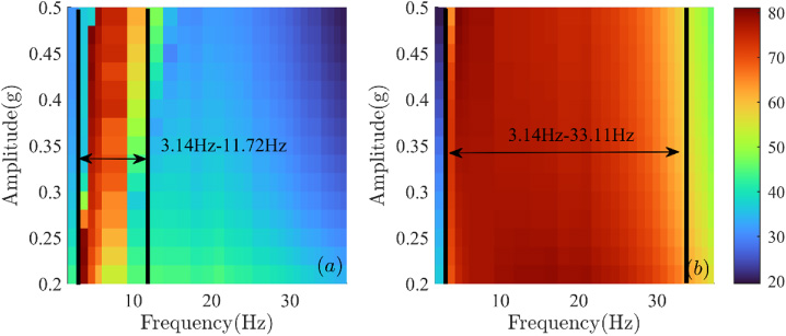
When the natural frequency of the multi-storey structure changes, the vibration reduction effect of the TMDVA under different excitation amplitude. (a) F-TMDVA. (b) EF-TMDVA.
Both the F-TMDVA and the EF-TMDVA can achieve broadband vibration reduction effectively, but the mechanism of their broadband vibration reduction is different. Because of the nonlinear stiffness of the magnetic force, the F-TMDVA can form a lot of nonlinear resonance conditions with different primary structures. Hence, the F-TMDVA can be engaged in resonance capture with multi-storey structures with different natural frequencies, so that the broadband vibration reduction of the F-TMDVA is achieved. Also, due to the nonlinear stiffness, the broadband vibration reduction effect of the F-TMDVA has a strong dependence on the excitation amplitude. In contrast, the movement range of the magnet B in EF-TMDVA is always located in the quasi-linear interval of the magnetic force, resulting in a single resonance condition. Thus, the broadband vibration reduction performance of the EF-TMDVA is achieved by large damping. Taken together, adjusting the ECD coefficient properly can improve not only the overall vibration reduction performance of the TMDVA, but also its robustness.
The TMDVA proposed in this paper is compared with other DVAs through Table 4 (the vibration reduction effect is not reported in the Refs [29,30]). From the structural perspective, compared with other DVAs, the TMDVA has the simplest structure and is easy to fabricate, which is conducive to the miniaturization of the absorber. From the perspective of vibration reduction characteristics, the TMDVA can achieve both linear (with a large ECD coefficient) and nonlinear (with a small ECD coefficient) vibration reduction for the primary structure. Other DVAs can only achieve linear or nonlinear vibration reduction. From the perspective of the vibration reduction performance, the vibration reduction effect of the TMDVA is better than that of other DVAs.
Comparison of the TMDVA with other DVAs
It can be found that the TMDVA vibration reduction method has the following advantages:
Compared to the active and semi-active control methods, the TMDVA vibration reduction method does not need external energy input. Due to that, the TMDVA can be installed directly on the primary structure and effectively reduce the vibration of the primary structure. The structure of the TMDVA is very simple. It is easy to be implemented and miniaturized. TMDVA is a kind of dynamic vibration absorber that contains both ECD and Coulomb damping. The ECD coefficient of the TMDVA can be adjusted arbitrarily based on the accurate ECD calculation model derived in this paper. The EF-TMDVA has a wide tunable frequency range. Furthermore, in its tunable frequency range, the vibration reduction effect of the EF-TMDVA will not be affected by the excitation amplitude (input energy) of the system. And the vibration reduction effect of the EF-TMDVA can reach more than 80%. The TMDVA not only can achieve nonlinear vibration reduction, but also can realize linear vibration reduction with the combined effect of the ECD and magnetic quasi-linear stiffness. The TMDVA can be applied to the vibration reduction of structures with horizontal vibration characteristics such as beams, rods and multi-storey structures. And the tunable frequency range of the TMDVA makes the absorber exhibit good performance for low frequency vibration control.
Of course, there are some limitations of the TMDVA:
Since the TMDVA is a magnetic DVA, it is not suitable in strong magnetic environments and high temperature environments. These environments may cause the TMDVA to lose its vibration reduction effect. At the same time, the magnetic properties of the TMDVA may have some bad effect on the normal operation of electronic components. the vibration reduction effect of the TMDVA in medium and high frequency vibration reduction needs to be improved. The tunable frequency band of the F-TMDVA is narrow, of which the vibration reduction effect also needs to be further improved.
These issues need to be addressed in subsequent studies.
In this paper, a novel Triple-magnet Magnetic Dynamic Vibration Absorber (TMDVA) with Eddy Current Damping (ECD) and Coulomb damping is proposed. The TMDVA is composed of triple cylindrical permanent magnets, a damping tube and a PTFE tube. With its simple structure, it is easy to be implemented and miniaturized. Based on the ECD calculation model proposed in this paper, the ECD coefficient can be designed and adjusted arbitrarily. The full text demonstrates that adjusting the ECD coefficient properly can not only improve the vibration reduction effect of the TMDVA, but also reduce the sensitivity of the vibration reduction effect to the excitation amplitude as well as enhance the broadband vibration reduction performance and robustness of the TMDVA. Taken together, the TMDVA has potential application value in passive vibration reduction of engineering structures.
Footnotes
Competing interests
We declare that we have no financial and personal relationships with other people or organizations that can inappropriately influence our work, there is no professional or other personal interest of any nature or kind in any product, service and/or company that could be construed as influencing the position presented in, or the review of, the manuscript entitled, “Design and Modeling of a novel Triple-magnet Magnetic Dynamic Vibration Absorber”.
Data availability
The data that support the findings of this study are available from the corresponding author upon reasonable request.
Funding
This work is supported by the National Natural Science Foundation of China (grant no. 52275122) and the National Natural Science Foundation of China (grant no. 12132010).
Author contributions
All authors contributed to the study conception and design. Material preparation, data collection and analysis were performed by Xiaoyu Chen and Yonggang Leng. The experimental structures were made and prepared by Xiaoyu Chen. Fei Sun, Xukun Su, Shuailing Sun and Junjie Xu revised and polished the English writing of the manuscript. All authors read and approved the final manuscript.