
Abstract
In inductors excited by the inverter using gallium nitride power devices, the ringing phenomenon, which occurs due to the multi-resonances during the short rise and fall time, increases noise and loss. To clarify the mechanism of the multi-resonances, the high frequency (HF) behaviors of a ring core inductor in frequency domain are measured and simulated by using the 2D electromagnetic field finite element analysis taking account of the stray capacitance. It is shown that the multi-resonances can be simulated, and the simulated results are in good agreement with the measured ones. To explain this phenomenon, a distributed-element circuit model including the stray capacitance of the ring core inductor is proposed based on the simulated results, it is shown that the proposed circuit model can represent the HF behaviors of the ring core inductor well.
Keywords
Introduction
Recently to make power electronics equipment more compact and higher efficiency, the carrier frequency is increasing by applying the gallium nitride (GaN) – Field Effect Transistor, etc. 1 In inductors excited by the inverter using GaN power devices, the ringing phenomenon,2,3 which is the oscillation in the waveform of current occurs due to the multi-resonances during the short rise and fall time of input voltage, and it increases the noise and iron loss. The resonances are simulated by the equivalent circuits4,5 and the electromagnetic field finite element analysis (FEA) 5 taking account of the stray capacitance. However, the mechanism of multi-resonances seems not to be clear well.
In this paper, to clarify the physical mechanism of the multi-resonances, first, the high frequency (HF) characteristics of the input admittance
Measurement
Measurement model
The measurement model of the ring core inductor, in which a winding is wound around a plastic casing outside the ring core, is shown in Figure 1. The core is a magnetic solid one (JIS: SUS430) and the height hc of 35.35 mm is set to be much longer than the width wc of 2.46 mm so that 2D FEA can be applied. The winding has 254 turns of copper wire with the diameter ϕw of 1 mm and the total length lw of the wire is 24.26 m.

Measurement model, (a) whole view, (b) sectional view.
Measured result
The frequency characteristics of the input admittance
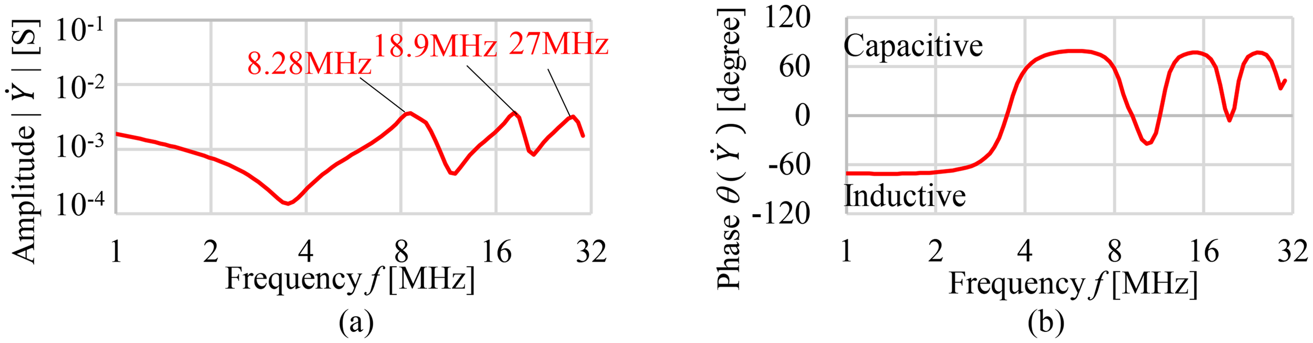
Input admittance
Electromagnetic field analysis
Analysis method
The electromagnetic field is analyzed by using the


Analysis model and conditions
In the analysis, the measurement model of the ring core inductor shown in Figure 1 is simplified into the 2D finite element (FE) model shown in Figure 3.
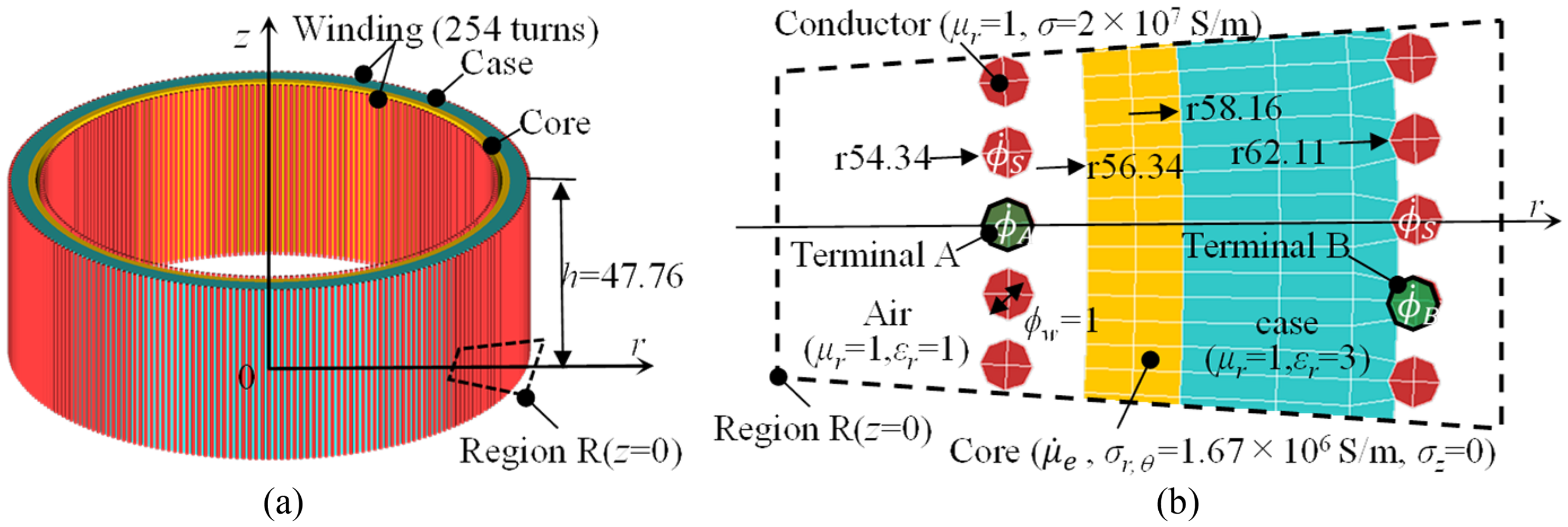
Simplified 2D FE model of ring core inductor, (a) full model, (b) enlarged view of region R.
The winding is simplified as the straight conductive bars, which are connected into a winding by using the numerical connection of nodes on the boundary. The voltage
The magnetic characteristics of iron core are assumed to be linear and the eddy current in the iron core is considered by the relative effective permeability
Results and discussion
Admittance
First, the admittance
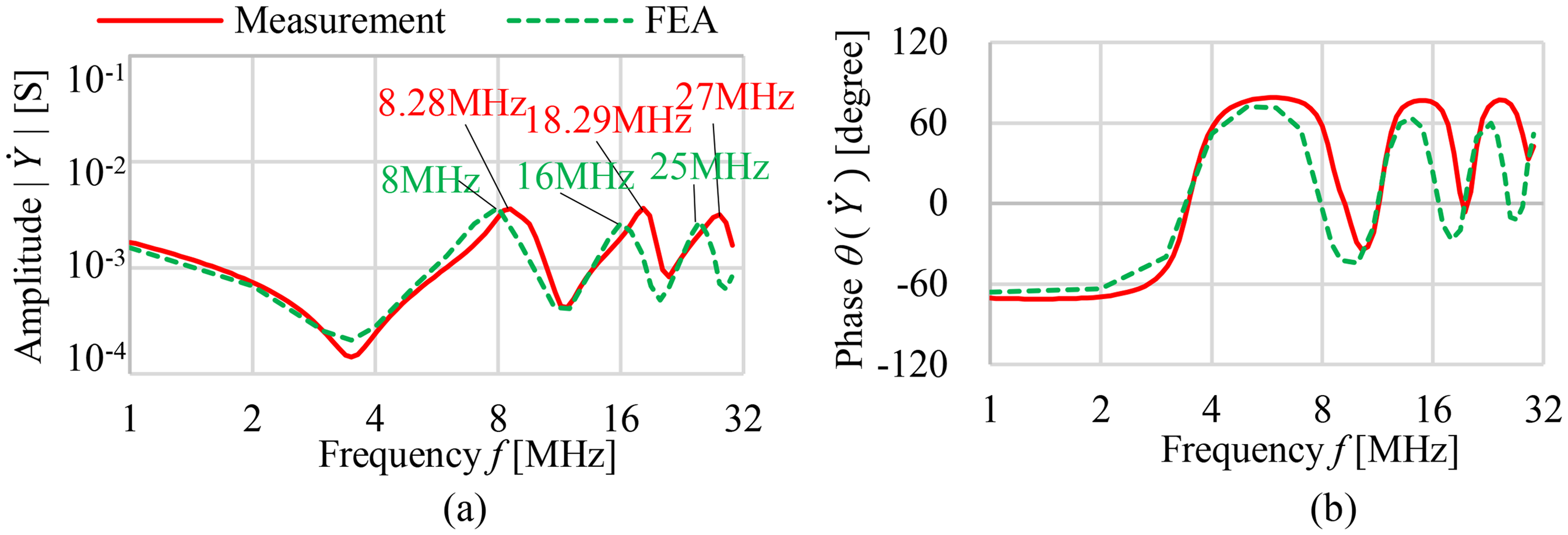
Input admittance Y of the ring core inductor (measurement and FEA), (a) amplitude, (b) phase.
Distributions of displacement current and electric scalar potential
Next, to investigate the mechanism of the resonance phenomenon in the ring core inductor, the distributions of displacement current and voltage are shown in Figure 5. In Figure 5(a), the displacement currents between the wires and core and between each turn of the wires can be observed, which lead to the stray capacitance of the winding. In Figure 5(b), from the distribution of the absolute value of the electric scalar potential ϕ at the wire and core versus azimuth θ at the resonant frequencies, the standing waves can be observed and ϕ becomes lager than the input source at terminal A of the winding.
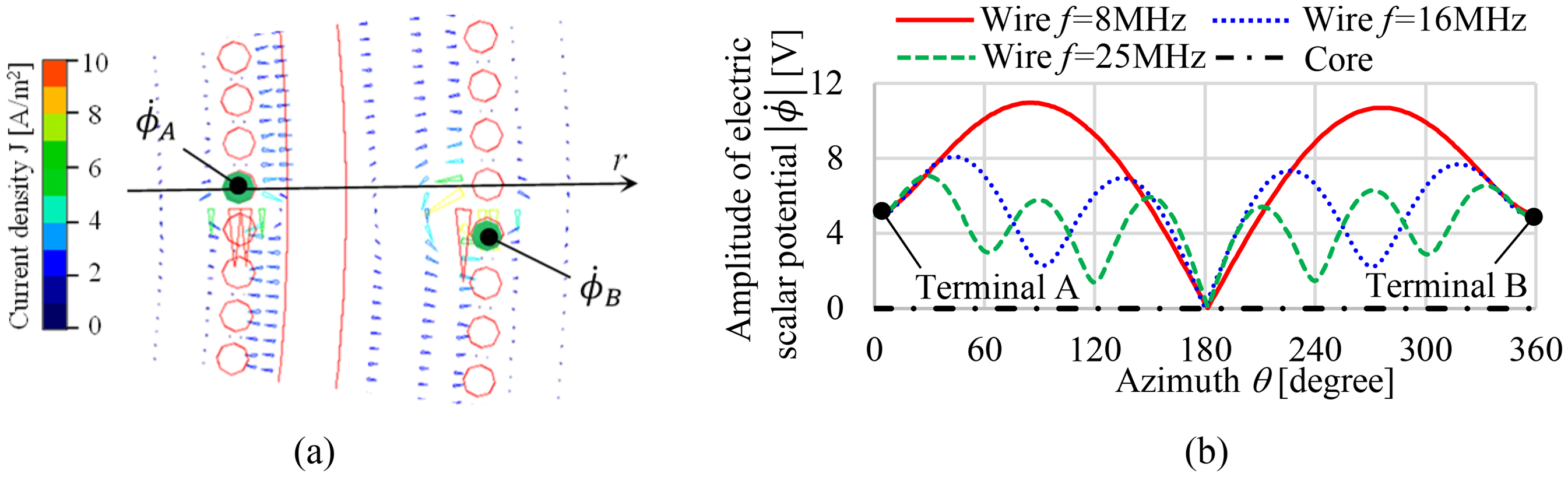
Distribution of displacement current density and voltage, (a) displacement current outside the wire and core at region R (f = 8 MHz), (b) voltage of the wire and core.
The wavelength of the electromagnetic wave (f = 8 MHz) is from 21.65 m to 37.50 m with different velocity in air (εr = 1, μr = 1, cair = 3.00 × 10⁸m/s) and plastic case (εr = 3, μr = 1, cair = 1.73 × 10⁸m/s), and the length of the wire is 24.26 m, which is in this range. Therefore, the multi-resonance phenomenon can be explained by the wave propagation process and self-resonance explained by the distributed-element circuit of the transmission line, besides, the distributed-element circuit analysis is performed to verify this explanation in the Section 4.
Distributed-element circuit analysis
Circuit model
To explain the multi-resonances of the ring core inductor from the perspective of circuit analysis, the distributed-element circuit shown in Figure 6 is proposed based on the electromagnetic field analysis and the transmission line theory.
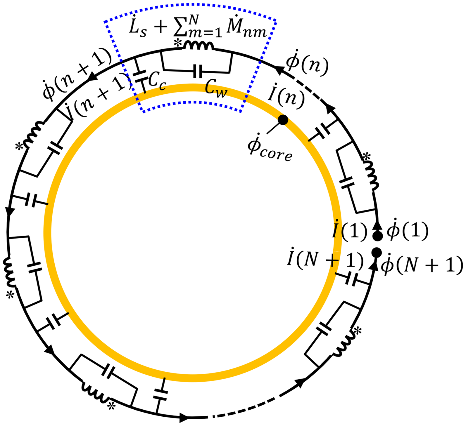
Distributed-element circuit of ring core inductor.
Circuit analysis method
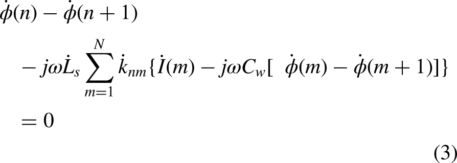
The basic circuit equations of the distributed-element circuit shown in Figure 6 are as follows:

Results and discussion
The circuit parameters can be obtained using the analysis model shown in Figure 3. The stray capacitances Cw, Cc are calculated by using the electrostatic field analysis. The calculated values are Cw = 3.15 pF/turn, Cc = 1.1 pF/turn. The self-inductance
The frequency characteristics of
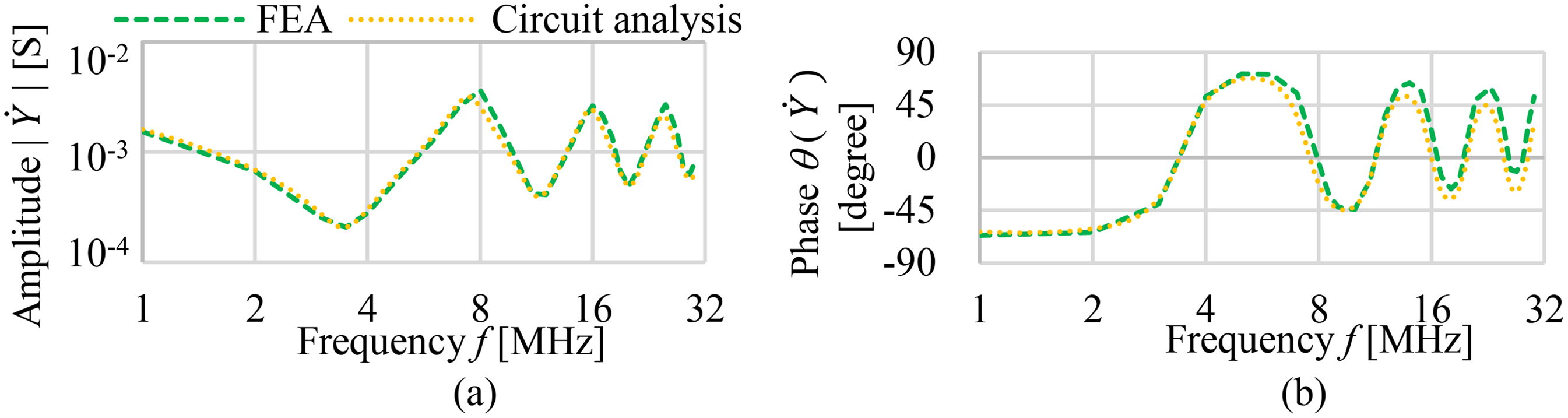
Input admittance Y of the ring core inductor (FEA and circuit analysis), (a) amplitude, (b) phase.
Conclusion
The frequency characteristics of the ring core inductor at HF are analyzed by using the 2D electromagnetic field analysis taking account of the displacement current. The simulated input admittance
In the future research, the FEA taking account of the nonlinearities or frequency characteristics of the material constants of the iron core and plastic case should be carried out. Moreover, the method to remove the ringing phenomenon in inductors will be investigated using the electromagnetic field analysis and the circuit analysis proposed in this paper.
Footnotes
Acknowledgements
This work was partly supported by JSPS KAKENHI Grant Number JP23K03820.
Funding
The authors received no financial support for the research, authorship, and/or publication of this article.
Declaration of conflicting interests
The authors declared no potential conflicts of interest with respect to the research, authorship, and/or publication of this article.