
Abstract
Lightly saturated induction machines can improve material utilization. However, the magnetic saturation effect and its axial variation due to skew may lead to high noise levels. In order to improve the calculation accuracy of the magnetic noise, this study proposes an analytical model of the magnetic saturation, which newly introduces the permeance difference to quantify the axial variation. Using the harmonic analysis, the magnetic flux density and electromagnetic force are extracted via Fast Fourier Transform (FFT). The saturation magnetic flux density is nearly sinusoidal at different axial positions of the skewed rotor. The influence of skewed angle on saturation harmonics is discussed based on comparison between two kinds of skewed-rotor motors. Compared with the single-skewed rotor, the dual-skewed rotor with inverted structure hinders the rapid change of saturation harmonics. The validity of saturation model with axial variation is verified through the coupled simulations and noise experiments. The proportion of saturation harmonic is raised with significantly reduced slot harmonics by the dual-skewed rotor. Compared with the regular skewing design, the optimized skewed distance of 0.9 slot pitch achieves the lower noise level in dual-skewed rotor induction machine.
Introduction
The noise in induction machines has been continuously studied with the increasing demands on the motor performance. The acoustic noise is generally divided into four types, i.e., the magnetic noise, mechanical noise, aerodynamic noise, and electronic noise, according to the source of the noise. 1 In some literatures, the electronic noise caused by the nonlinearity of the power supply is classified into the magnetic noise.2–4 Among these types of noise, the source of the magnetic noise is the electromagnetic force generated by the air-gap magnetic field.5,6 There are several factors that will lead to the introduction of the harmonic magnetic field in induction machines. Considering the saturation of iron core, the introduced harmonics might modify the electromagnetic force spectrum and further create new harmful resonances. 7 Thus, the accurate magnetic field calculation considering the saturation effect is crucial to suppress the magnetic noise during the design stage.
The methods to calculate the magnetic field in the induction machines could be roughly classified into the analytical and the numerical methods. Compared with the time-consuming numerical method, such as finite-element method (FEM), it is flexible to obtain closed-form solutions with the analytical field solutions in the form of Fourier series.8,9 Many efforts to incorporate the magnetic saturation into the induction machine models have been reported, as summarized in. 10 However, most of the efforts are devoted to analyze the effects of the fundamental component. The saturation effect is firstly modeled by introducing a function of variable air-gap length with saturation level taken into consideration. 11 Base on this classical analytical model, the saturation effect is characterized with two saturation factors. The dominant third saturation harmonic is included in the air-gap magnetic field model. 12 To accelerate the calculation speed of the dynamic analysis, the subdomain technique is applied to predict the saturation level in induction machines. 13 The above saturation models could well suit for the specific applications. However, the analytical models of saturation effect are mostly established based on the assumption of straight-slot rotor. The influence of the skewed rotor on the saturation effect is normally ignored, which may lower the calculation accuracy of the magnetic noise.
The rotor skewing is actually a traditional and widely-used technique aiming to reduce the magnetic noise in induction machines. The optimal skewing of the single skewed rotor is around one stator slot pitch.1,14 With the appropriate skewing design, the odd slot harmonic magnetic field may be eliminated. Besides, many innovative designs of the rotor structure have been proposed to reduce magnetic noise.15–18 The structure of rotor core notching is constructed to reduce the rotor permeance harmonics. In addition, the number of equivalent rotor slot is increased. These improvements help to reduce the vibration and acoustic noise. 15 Utilizing the phase shift effect, the asymmetrical straight rotor is designed to eliminate the slot harmonics caused by the slot opening, and reduce the resulting noise component. 16 The slot harmonics account for the largest proportion of the harmonic components. In order to further suppress the rotor slot harmonics, the single skewed rotor is developed into several novel rotors with the multi-segment structure17 1.8 Among them, the rotor with the two-segment skewing is relatively convenient to manufacture. Compared to normal skewed rotor, this dual skewed rotor has the enhanced capability to reduce the vibration and acoustic noise. 19 Moreover, the dual skewed rotor could offset the axial forces and suppress the torque ripples, and evidently reducing the even-order harmonic magnetic field. 20 However, proportion of the saturation harmonics may increase due to the reduction of slot harmonics. In this case, extra attention needs to be paid to the saturation harmonics when establishing the analytical model of the magnetic field. And without considering the axial variation of the saturation harmonics, the calculation accuracy of the magnetic noise would be further reduced.
Aiming to reduce the magnetic noise in induction machine with the dual skewed rotor, this paper explores the effect of the magnetic saturation and its axial variation on the magnetic noise. The working principle of the dual skewed rotor is firstly discussed to reveal how it achieves the decrease of the slot harmonic EMFs. Then, the axial variation of the magnetic saturation is modeled incorporating the phase difference in the equivalent air-gap permeance. The radial electromagnetic forces, as the dominant cause of magnetic noise, are calculated and classified according to the harmonic generation source. By utilizing the two-dimensional (2D) FEM, the saturation radial forces are calculated to verify the proposed modeling of the axial variation due to skew. At last, both the simulation and experiment verification are carried out on two kinds of motors with different skewed angles to verify the theoretical results.
Axial variation of magnetic saturation due to skew
Basic structure of dual skewed rotor
The structure of dual skewed rotor is developed from the traditional single skewed rotor, as shown in Figure 1. Along the orientation of the shaft, the dual skewed rotor contains two single skewed rotors assembled with inverse directions to offset the axial forces. 20 The corresponding skewed distances are bsk1 and bsk2, respectively. And the corresponding axial lengths are l1 and l2, respectively. The two single skewed rotors are axially connected by an intermediate ring of negligible length. Along the circumference direction, the two single skewed rotors stagger with each other by a stagger distance bst. In order to simplify the production process, the design of the dual skewed rotor usually adopts the symmetrical structure. In other words, the two single skewed rotors are of the same skewed distance and axial length, i.e., bsk1 = bsk2 = bsk and l1 = l2 = l/2. l is the axial length of the rotor. The stagger distance is equal to the half of the rotor slot pitch, which is expressed as bst = t2/2.
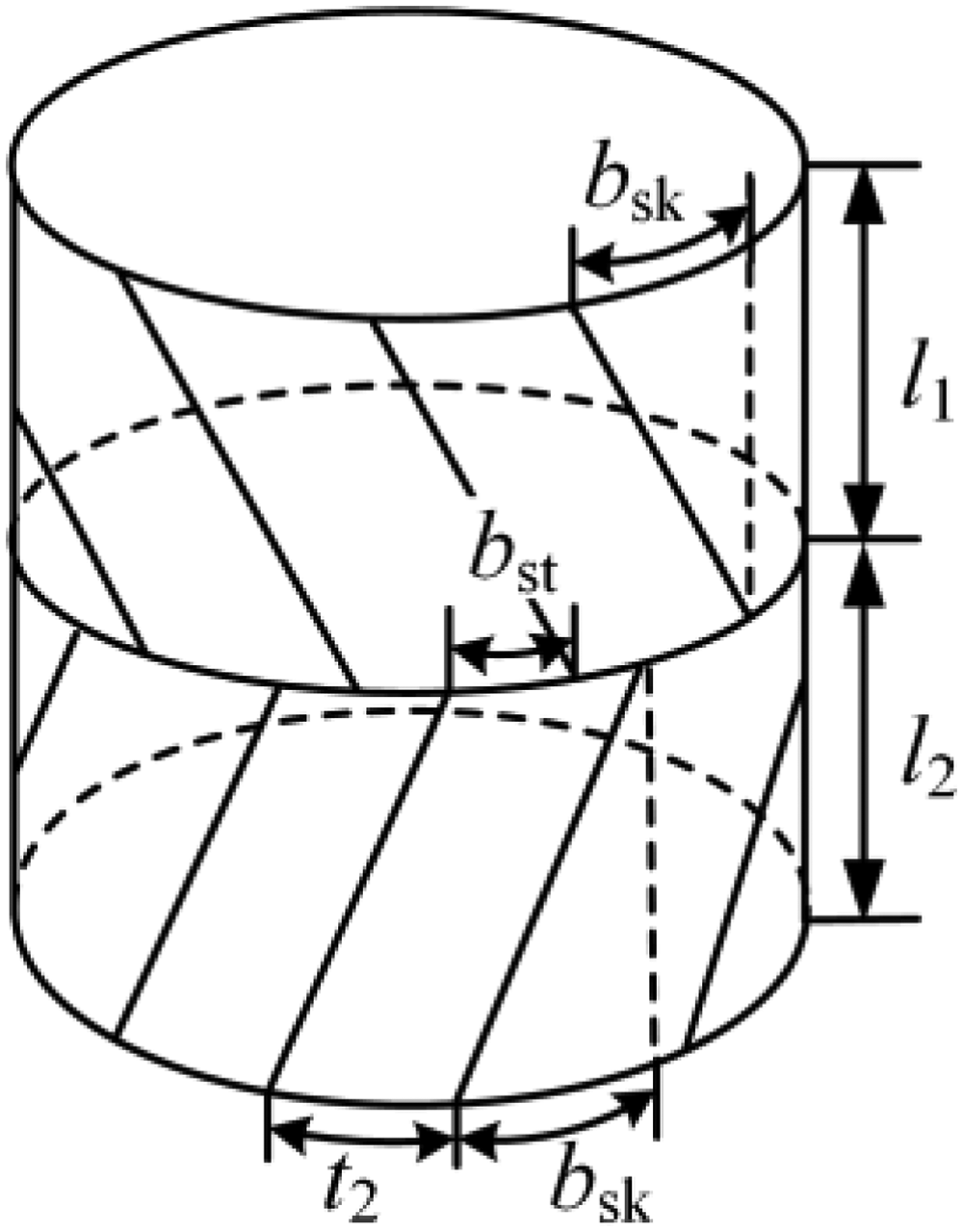
Schematic diagram of the dual skewed rotor.
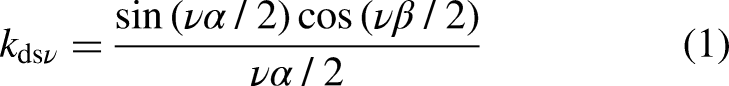
The induction effect of skewed rotor bar on the stator field is weaker compared to the case of straight bar. The skewing factor is derived to describe such weakening effect in calculations. Similarly, in the case of dual skewed rotor, the double skewing factor kdsν could be defined as
20
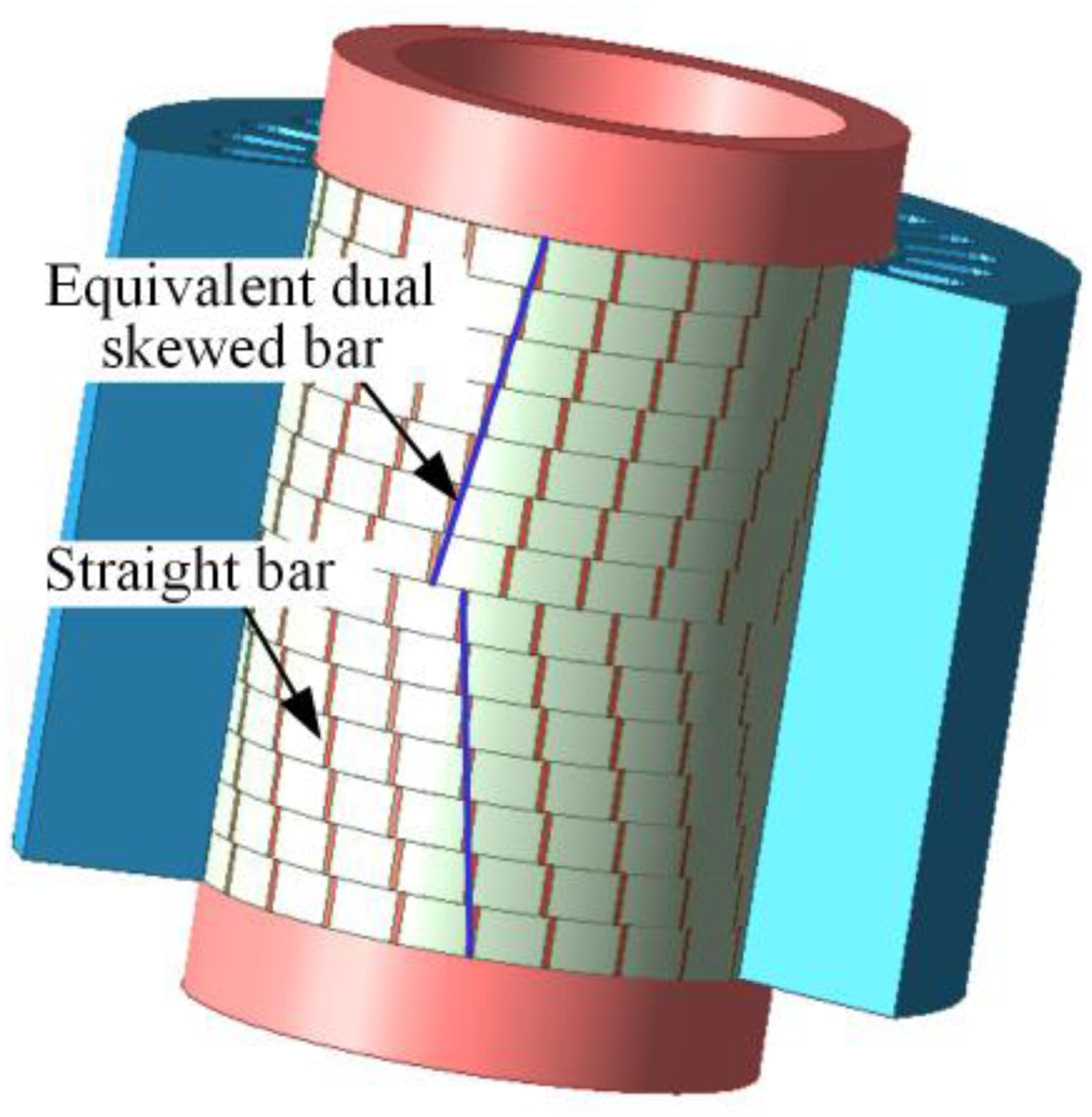
Structurally, the dual skewed rotor could be regarded as a combination of skewed rotor and staggered rotor. For such a composite rotor, there exist both the skewing effect and the stagger effect to weaken the slot harmonic EMFs, as shown in Figure 2. In the case of skewing effect, the skewed distance is the wavelength of the first-order slot harmonic magnetic field 2τν1. The relationship between the wavelengths of the first- and second-order slot harmonics is approximately expressed as τν1 = 2τν2. The harmonic EMFs
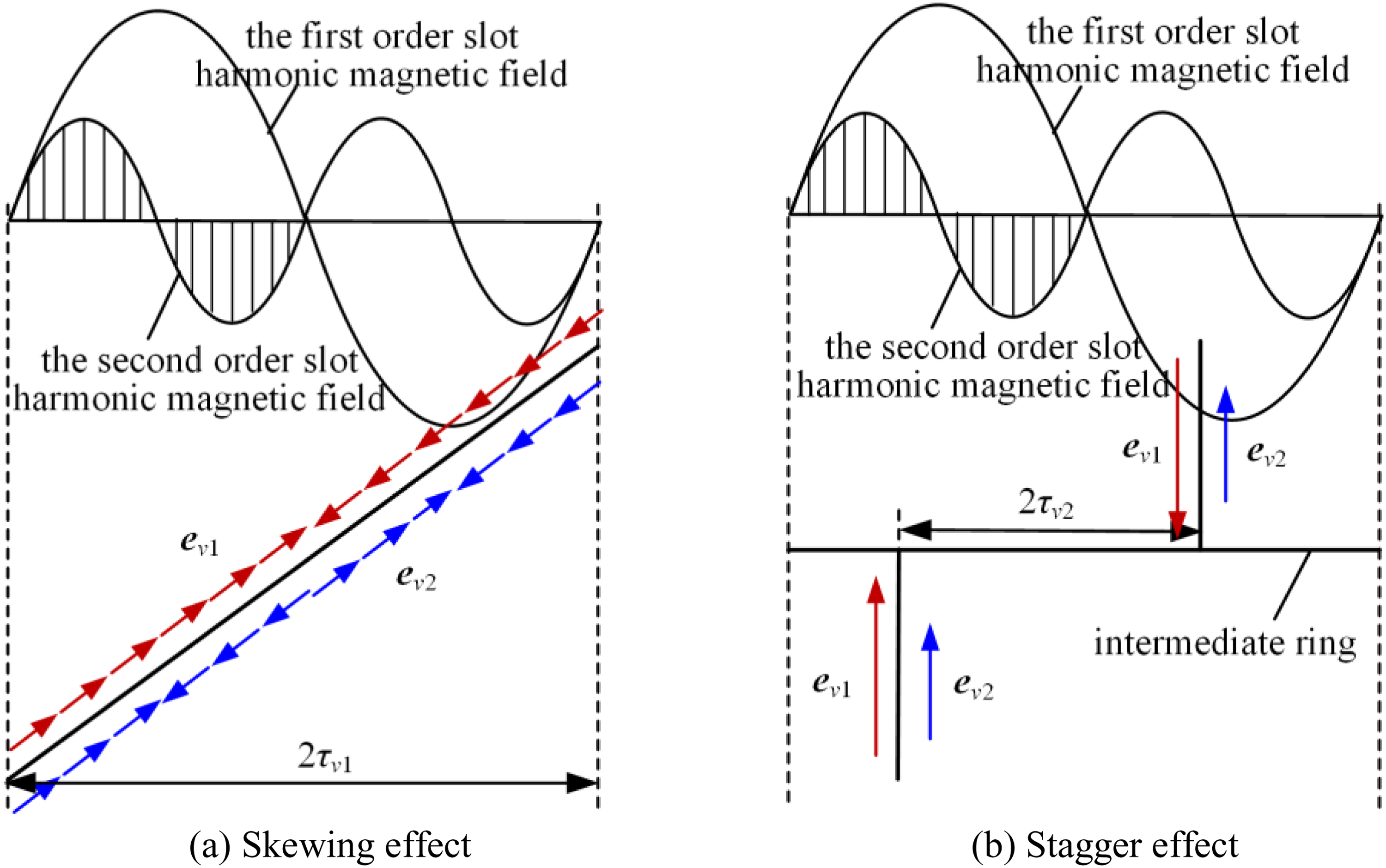
Skewing and stagger effect of dual skewed rotor to weaken the slot harmonic EMFs.
Saturation harmonic permeance
The nonlinear magnetizing curve of the ferromagnetic material is the intrinsic cause of the saturation effect in electrical machines. The regional saturation effect results in the permeability difference of the iron. To keep the assumption of constant and infinite iron permeability, the equivalent air-gap length based on a function of saturation level is applied to consider the saturation effect,
11
as given by

The inverse function of the air-gap length could be converted into the permeance function, while the sinusoidal feature is assumed to be unaltered. The modified air-gap permeance considering the saturation effect is obtained as


Λ0=µ0/g0 is the constant air-gap permeance, Λʹ0 is the equivalent air-gap permeance considering the saturation effect. µ0 is the air permeability. Λ k sa=µ0/gksa is the saturation harmonic permeance.
When the stator and rotor sides are both slotted, the compound permeance coefficient is the product of the two permeability coefficients. By ignoring the cross-multiplied components, the harmonic permeance only considering the slotting effect is simplified as

ω1 is the angular frequency of power supply, s is the slip, Λ k s and Λ k r are the amplitudes of stator and rotor harmonic permeances, Zs and Zr are the numbers of stator and rotor slots, ks and kr are the stator and rotor permeance harmonic orders, respectively.
As for the motor with skewed poles or slots, both the relative position of stator and rotor, as well as the saturation permeance, vary axially on the coordinate z. Taking the dual skewed rotor as an example, the axially varied saturation permeance due to the skew could be expressed as
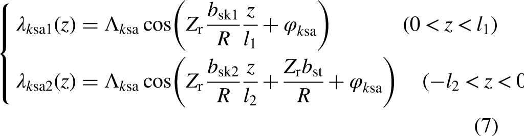
The saturation harmonic permeances essentially result from the deformation of magnetic field waveform due to the permeability difference. Thus, the permeance amplitude indirectly depends on the relative position of stator and rotor teeth. Considering the inclined rotor bars, this relative position varies both with time as quantified by (3), and with axial coordinate as quantified by (7).
Air-gap harmonic magnetic flux density
The air-gap MMF caused by discretization of winding could be divided into the fundamental and harmonic components. The amplitude of the latter is very small and thus neglected in this section. Assuming that the initial phase is zero, the fundamental MMF could be expressed as

The air-gap magnetic flux is produced by the interaction between the fundamental MMF and the air-gap permeances. By substituting the air-gap permeance in (3), two kinds of magnetic field are generated. The fundamental-frequency magnetic flux density could be expressed as

The other high-frequency magnetic flux density could be considered as the saturation harmonic magnetic flux density, which is simplified as

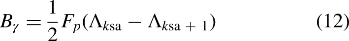
γ is the saturation harmonic order, which is expressed as γ=1 + 2ksa.
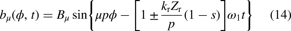
Considering the slotting effect, the slot harmonic components are generated by interaction between the fundamental MMF and the slot harmonic permeances in (5). The stator and rotor slot harmonic flux densities are expressed respectively as

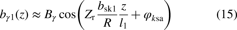
In the case of straight poles or slots, the amplitude of the rotating magnetic field modeled with (9)-(14) remain constant at different axial positions. However, in the case of skewed rotor, these harmonic components vary along the axial coordinate. Mathematically, the phase angle of the magnetic flux density is equal to that of the corresponding harmonic permeance. Considering the axial variation in (7), the saturation flux density in the range of 0 < z < l1 is modified as
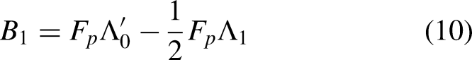
The saturation flux density of the other half rotor can be similarly deduced. Thus, the average flux density of the entire rotor is obtained by utilizing integral equation. In the case of symmetrical dual skewed rotor, the average saturation flux density is simplified as
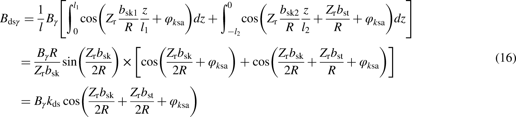
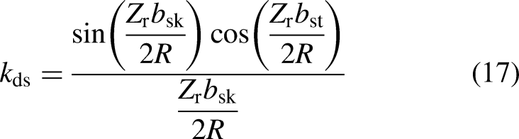
In the case of dual-skewed rotor, the varied saturation permeance directly lowers the average saturation flux density. The saturation dual-skewing factor kds is derived to quantify the reduction of its amplitude. It is found out that, the saturation flux density is only related to the initial phase when bsk and bst are equal to zero. On the other hand, the varied saturation permeance indirectly change the equivalent air-gap permeance. The fundamental magnetic density is also affected by the skewing parameters to a certain extent. The amplitude change of the flux density is partially caused by the change of corresponding permeance component.
Radial electromagnetic forces
The magnetic flux passing across the air gap produces a series of electromagnetic force component on the stator core. Among them, the radial electromagnetic force is the main source of the magnetic noise.
1
Utilizing the Maxwell's stress tensor, the radial forces can be approximated by21,22
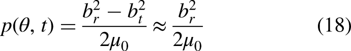
An arbitrary flux density produces one force wave on its own, and produces force waves by interacting with other flux densities. The radial electromagnetic force generated by the fundamental and saturation flux density is expressed as
The magnetic noise caused by the electromagnetic force is related to the amplitude of the radial force. On the other hand, the distance of the radial force wave is increased with the decreased order of the radial force wave, when the core is bent and deformed. Thus, extra attention is drawn to the radial forces generated by two kinds of magnetic field. Considering the fundamental and rotor harmonics, the radial force resulting from their interaction can be expressed as
As for the rotor and saturation harmonics, the radial force resulting from their interaction can be expressed as
The basic parameters of the radial forces in (19)-(21) are listed in Table 1. The saturation magnetic field complicates the radial forces of the motor. For example, it not only generates new radial force shown in row 3, but also increases the amplitude of the lower-order radial force shown in rows 4 and 6. Considering the axial variation in dual skewed rotor, the saturation permeance only reduces the amplitude of the average flux density and thus the corresponding radial force. For radial electromagnetic force of different orders, the impact of skewing parameters on the spatial order and angular frequency shows independent characteristics from each other.
Basic parameters of radial electromagnetic force wave.

Finite element simulation of radial electromagnetic force
Two-dimensional multi-slice FEM
The FEM formulation typically involves converting the governing strong form of the differential equations into a weak form. This weak form could be derived using the weighted residual method (WRM) and energy functional approach.25,26 The former method is applied in this section to solve general physical problems. In order to shorten the simulation process, the 2D multi-slice FEM is adopted to simplify the skewed-rotor. 27 The whole rotor is divided into several tiny straight-slot rotors, as shown in Figure 3. The axial position of the rotor varies gradually until an equivalent skewed angle is formed. The intermediate ring in the middle of the rotor is ignored in the modeling due to its negligible impact on the magnetic field. 20
2D multi-slice model of dual skewed rotor.
Harmonic analysis of air-gap magnetic flux density
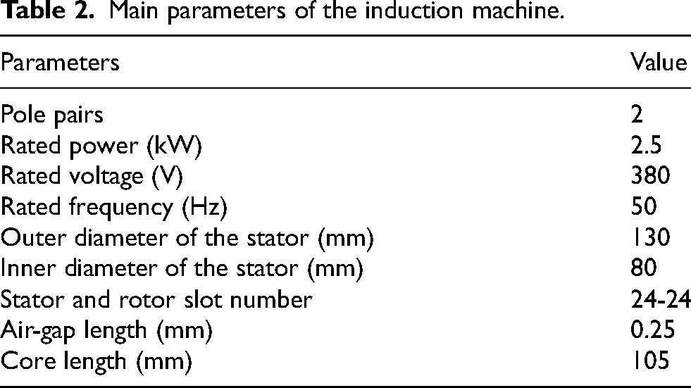
The main parameters of the example induction machine are listed in Table 2. The 24-24 slot combination is selected to ensure that, the relative position of the stator and the rotor remains constant under no-load condition of the motor. Problems caused by the equivalent slot combination in the starting process of the motor could be solved by applying the dual skewed rotor. 28 The adopted multi-slice model of the skewed rotor is composed of 30 straight-rotor models. Among them, an arbitrary simulated result is adopted as the approximated result of the skewed-rotor IM in a certain axial position. The waveform of motor radial air-gap magnetic flux density is shown in Figure 4, and the corresponding Fast Fourier Transform (FFT) result is shown in Figure 5. As for the high-frequency harmonics, featured as the equal spatial and time orders, the marked 3rd and 5th -order flux densities belong to the saturation harmonic. Especially, the 3rd -order saturation harmonic originates from the first-order saturation permeance.
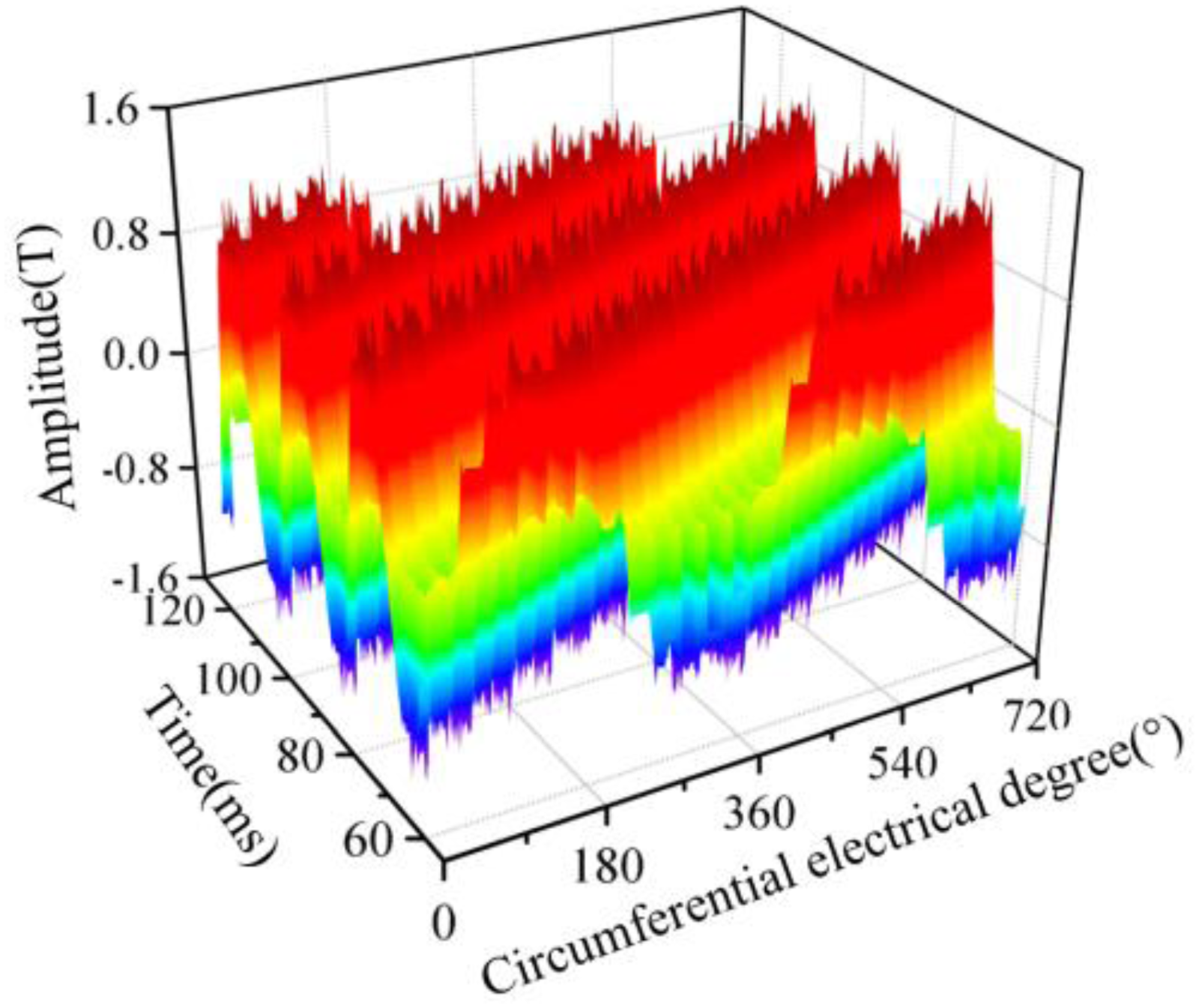
Space-time distribution of radial air-gap flux density.

2D-FFT result of radial air-gap flux density.
Main parameters of the induction machine.
As shown in Figure 6, the fundamental and third order flux densities are extracted from the calculation result of straight-rotor models. The varying rotor position represents the axial coordinate. The flux density amplitude nearly forms the sinusoidal waveform, and the spatial periods are both close to one slot pitch. The maximum value of the third order flux density increases by 3.6% relative to the average value. The saturation harmonic is more susceptible to the axial variation due to skew.
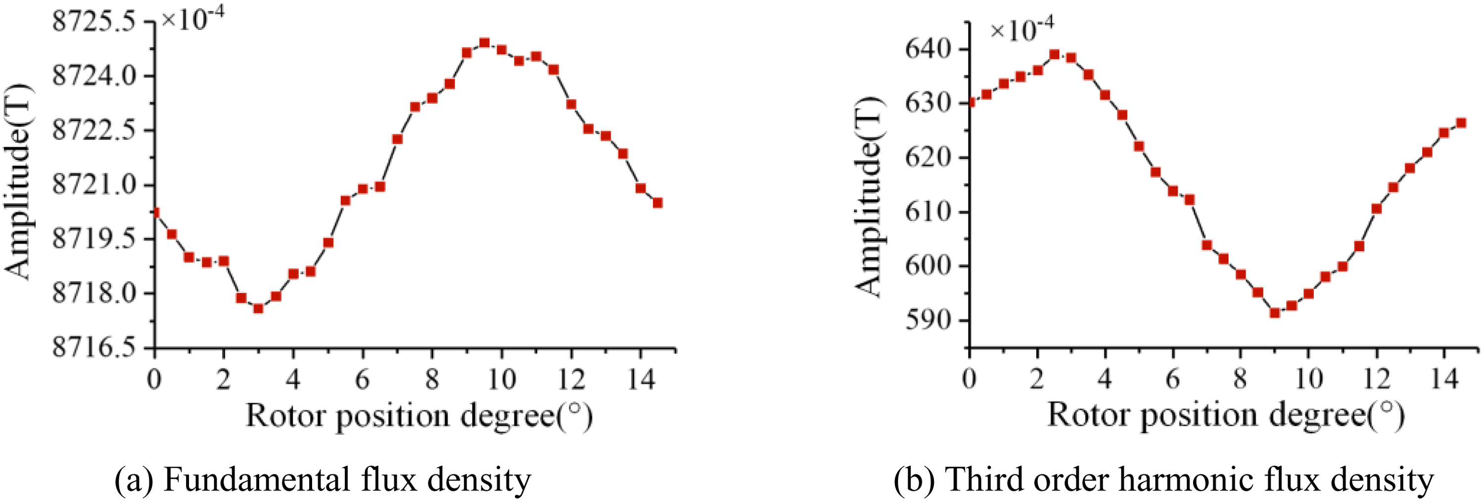
Curves of radial air-gap flux density components with different rotor positions.
As shown in Figure 7, the average air-gap flux densities are calculated by utilizing the equivalent skewed-rotor model. The skewed angle varies within the range of 0.8 to 1.2 slot pitch. The fundamental flux density remains almost unchanged no matter what the rotor type is. However, in the case of single skewed rotor, significant increase in the amplitude of the third order harmonic is observed as the skewed angle approaching the higher value. The variation trend of amplitude is reversed with opposite direction of the skewed rotor. Thus, the dual skewed rotor could mitigate the rapid change of the amplitude of saturation flux density.
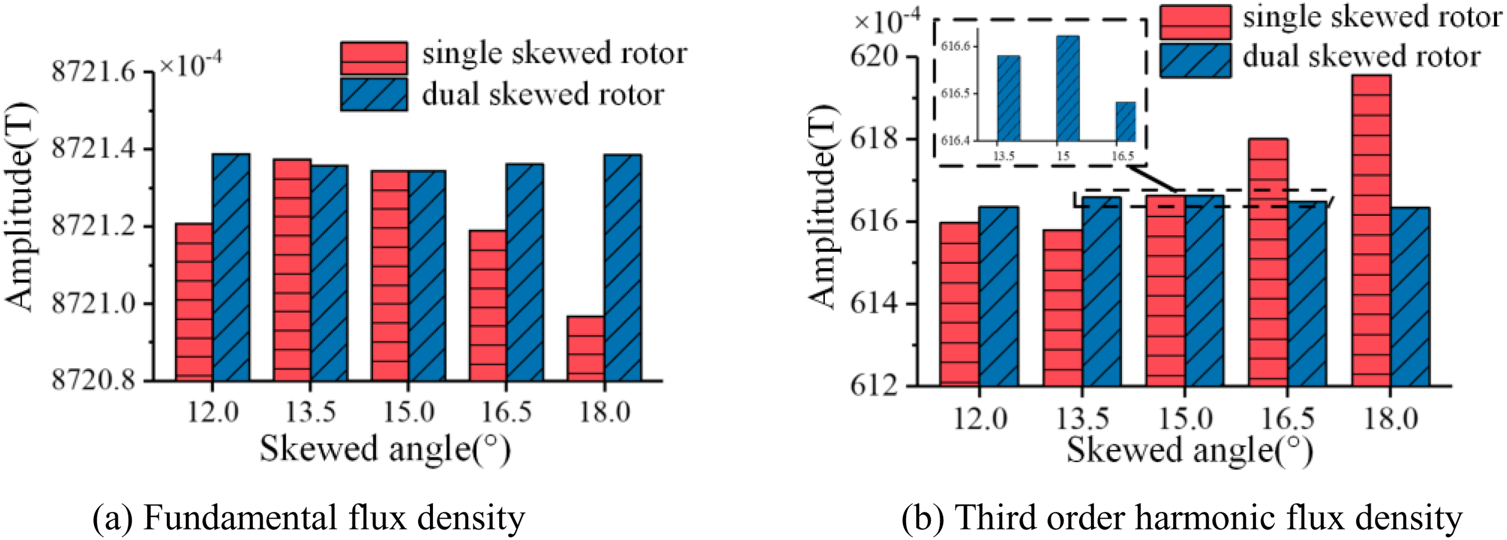
Average values of radial air-gap flux density components with different skewed angles.
Harmonic analysis of radial electromagnetic force
The waveform of motor radial electromagnetic force is shown in Figure 8, and the corresponding FFT result is shown in Figure 9. The radial forces generated by the fundamental and saturation flux densities are marked as four special components. These marked forces correspond to the first four items in Table 1, where the order of the saturation harmonic is 3. Specifically, the zero-order force component with the highest amplitude is generated by the fundamental and saturation harmonic itself. The 4th and 8th -order forces are both generated by the fundamental and 3rd -order saturation harmonic. Only the 12th -order force component is entirely generated by the saturation harmonic magnetic field. Considering the relative magnitude of magnetic field, the 4th and 12th -order radial forces are selected to reflect the fundamental and saturation flux density, respectively.

Space-time distribution of radial electromagnetic force.

2D-FFT result of radial electromagnetic force.
As shown in Figure 10, these two selected radial force components are extracted from the calculation results of different straight-rotor models. Their waveforms are both close to the sinusoidal shape, which is similar to the case of harmonic flux density. Relative to the average amplitude, the peak-peak value of the 4th -order radial force increases by only 2%, while the maximum value of the 12th -order radial force increases by 46.1%. The radial force associated with the saturation harmonic proves to be more susceptible to the axial variation of the skewed rotor.
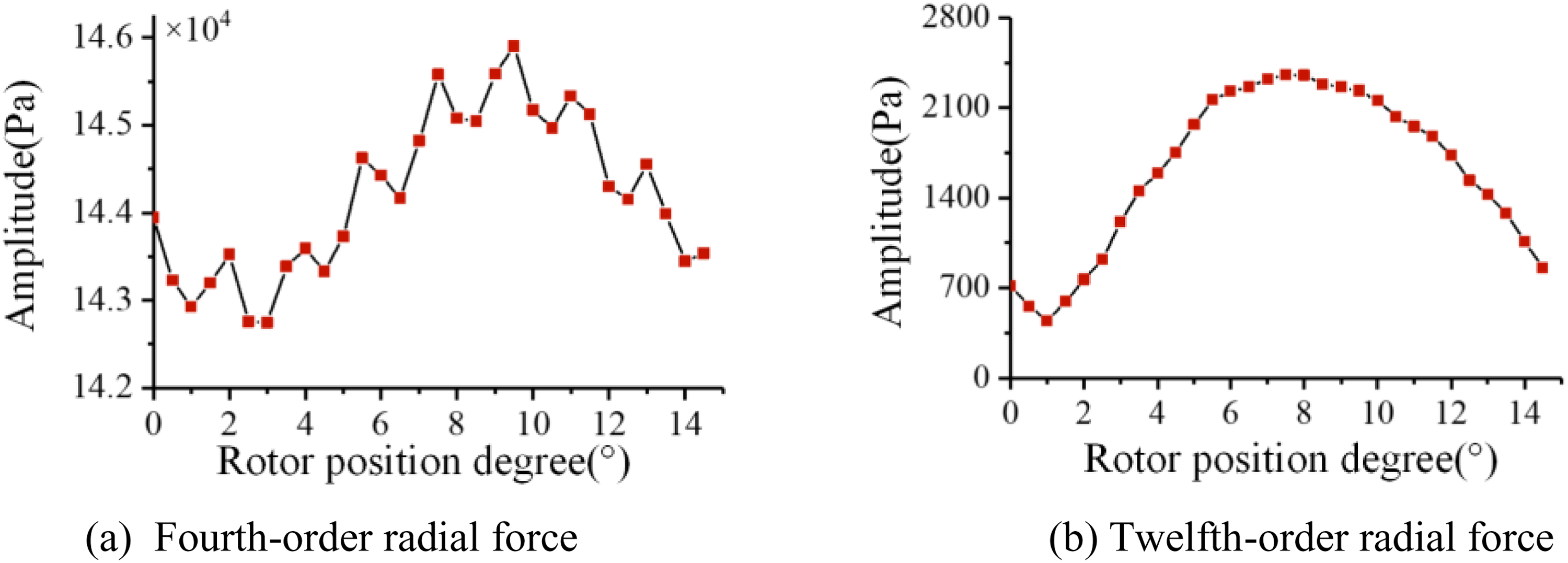
Curves of radial electromagnetic force components with different rotor positions.
As shown in Figure 11, the average radial forces are calculated by utilizing the former skewed-rotor models. The amplitude difference of the 4th -order radial forces remains almost unchanged no matter what the rotor type is. In the case of dual skewed rotor, the amplitude of the 12th -order radial force reaches its maximum value when the skewed angle is one slot pitch. Figure 7 and Figure 11 reveal that the variation trend of the radial electromagnetic force is similar to that of the flux density source. For the single-skewed rotor motor, significant change of the saturation flux density and its resulting radial force are observed with the increasing skewed angle, which can be effectively constrained by adopting the dual skewed rotor.
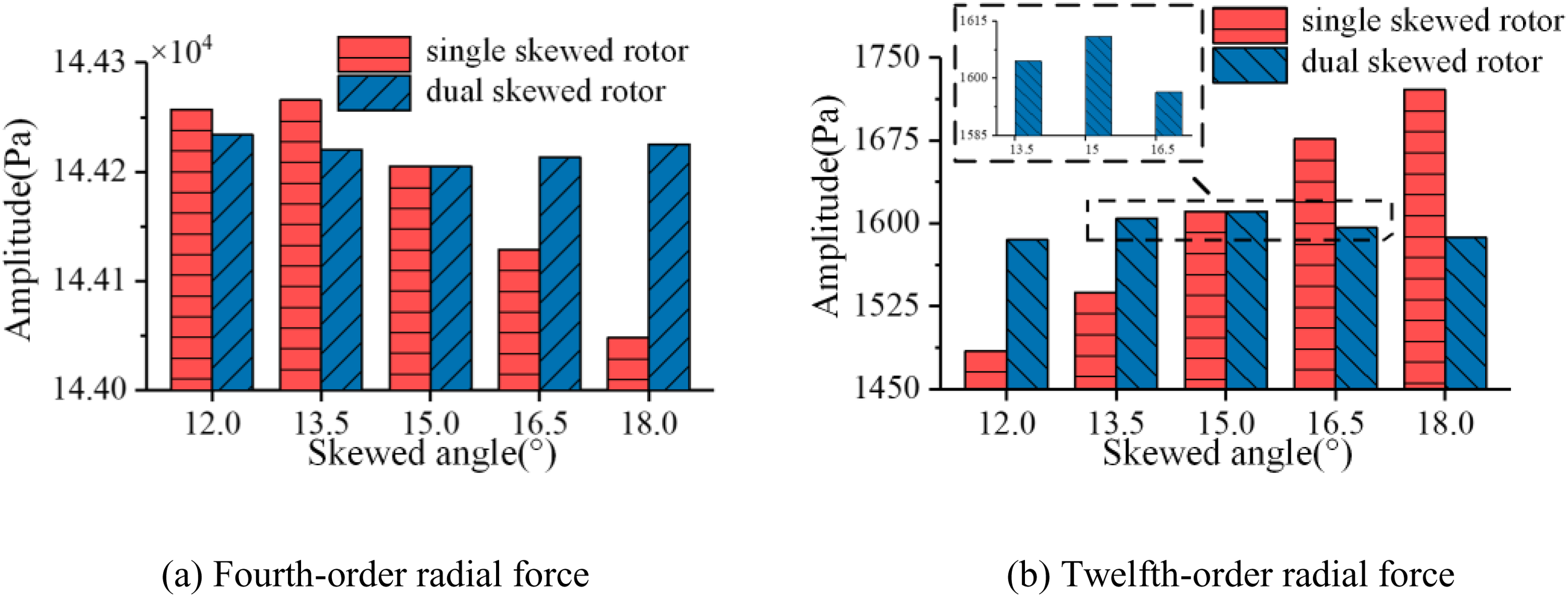
Average values of radial electromagnetic force components with different skewed angles.
Simulation and experimental validation of motor noise
Multi-physics coupling simulation
The 2D multi-slice motor model with 30 slices is firstly built to calculate the electromagnetic force on the surface of stator core. Then, the three-dimensional structural model is utilized to calculate the vibration and noise. The flow chart of the simulation process is shown in Figure 12. It includes the electromagnetic force calculation, radial force coupling, modal analysis, and harmonic acoustics, and the simulation results are further validated by the experiment test. To verify the theoretical analysis on the effect of the axial variation, two kinds of dual skewed rotor models are built for simulation and experimental verification. The skewed distances are 0.9 and 1.0 rotor slot pitch, respectively. Other structural parameters of two motors are identical to each other, as shown in Table 2.
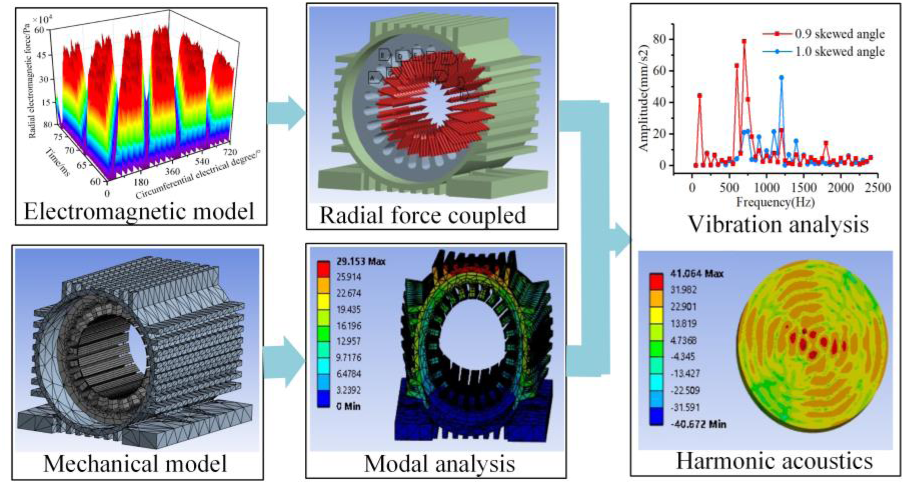
Simulation process of motor vibration and noise.
The modal analysis of the motor structure is crucial to determine whether resonance occurs in the motor. However, the electromagnetic forces generated by the saturation harmonics have a lower frequency, which is far below the natural frequencies of the motor. The effect of axial variation of magnetic saturation has little effect on the natural frequency. By applying the fixed constraints on the base position of the motor, the no-load noise of the two skewed-rotor motors is compared in Figure 13. The dominant frequencies of noise are the integral multiples of the slot number and the rotation frequency fr (fr = n/60), i.e., 24fr, 48fr and 72fr, which are normally denoted as slot frequencies. Compared to the case of 1.0 skewed angle, the noise amplitude of the first-order slot frequency in the IM is significantly reduced with the case of 0.9 skewed angle.
Comparison of no-load noise spectrum with different skew distances of dual skewed rotor.
Comparative test of prototypes with dual skewed rotor
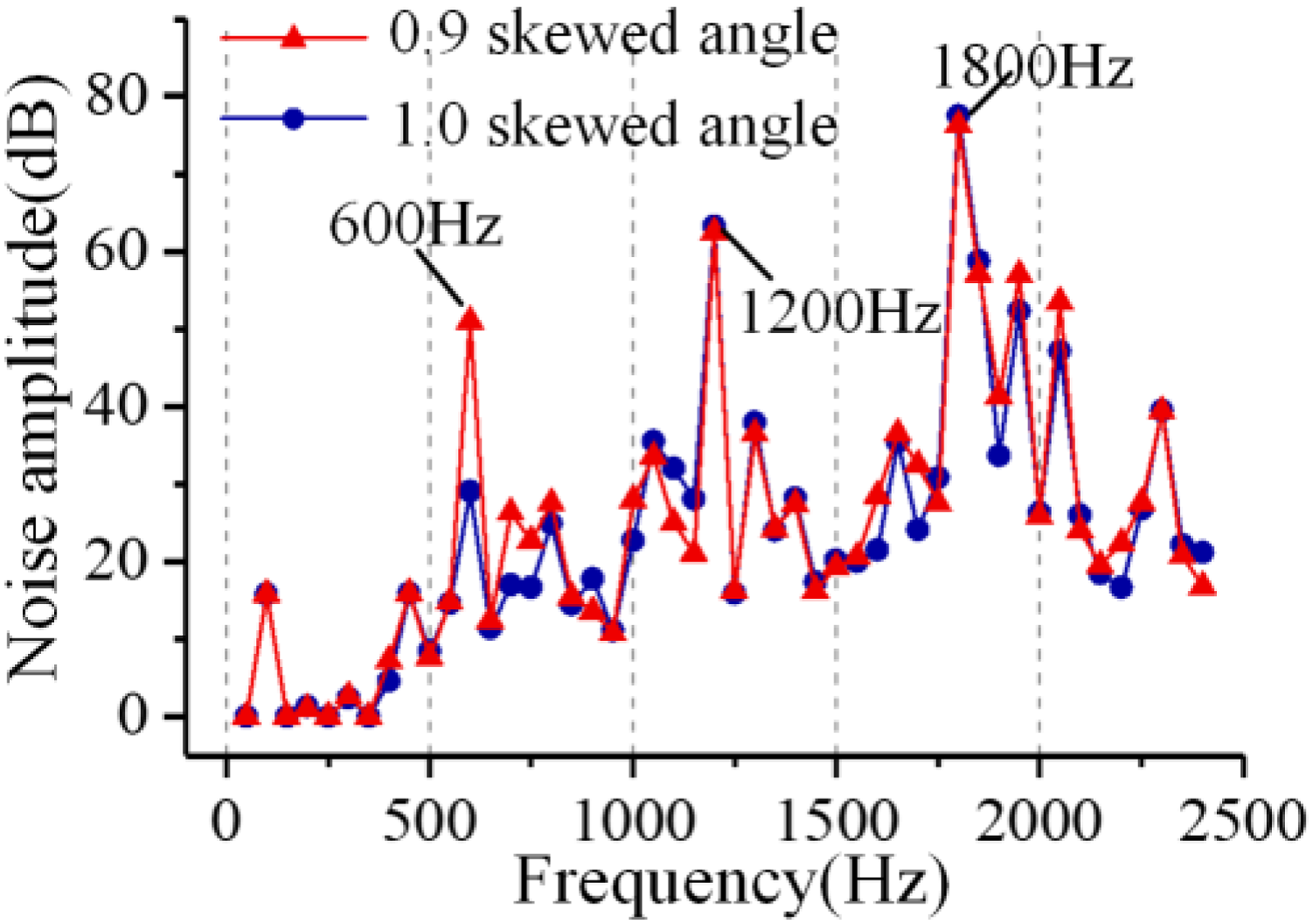
In order to validate the theoretical results, the experimental verification is carried out by measuring the no-load noise spectrum of two prototypes. One prototype of the tested dual-skewed rotors is shown in Figure 14. The test probes of the noise detectors are placed at identical positions of the two prototypes, to improve the precision of the comparison experiment. The comparison result of the noise test is shown in Figure 15. Only the noise spectrum below 2000 Hz is illustrated in Figure 15, as the effect of the magnetic saturation mainly exists within this frequency range. The complete low-frequency noise spectrum is more complicated and the amplitude difference of main noise components is smaller. The corresponding noise component may be observed at the frequency of radial electromagnetic force within the acceptable error of range, verifying their relation.
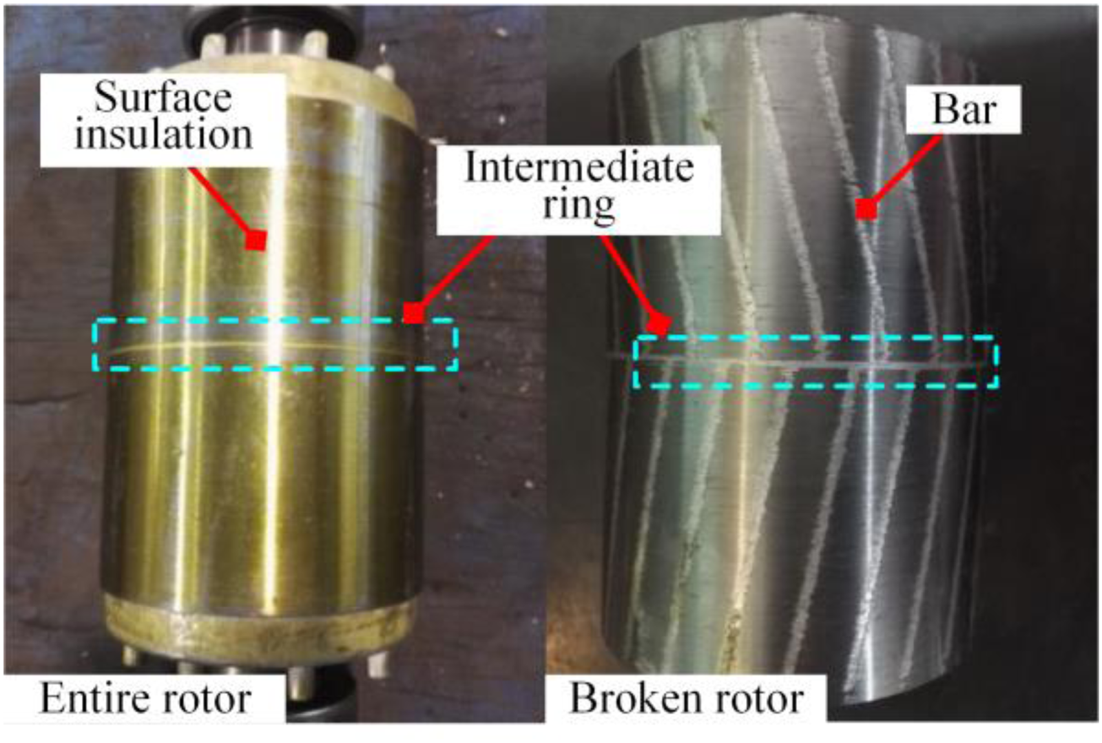
Prototype of dual skewed rotor with closed-slot shape.
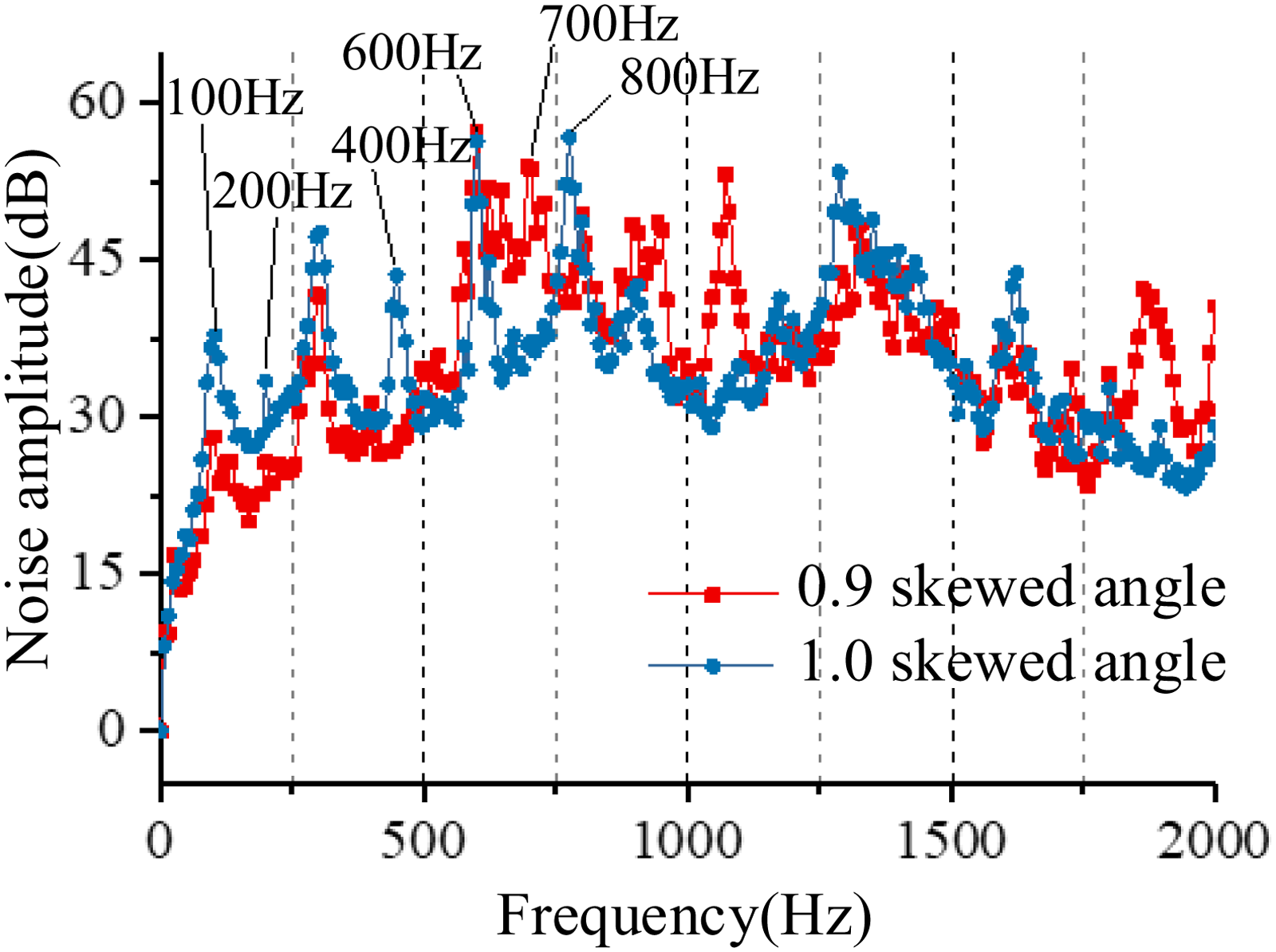
Comparison of no-load noise spectrum of two prototypes with dual skewed rotor.
The corresponding relations between the radial force and noise component are shown in Table 3. The involved harmonic magnetic field could be reflected from the expression of the radial force. Specific to the case of Table 3, the harmonic flux densities are the third-order saturation and the first-order rotor slot harmonic (γ=3, kr = 1). It is shows that the radial force generated by two kinds of flux densities has several noise components with different frequencies. In the meantime, one noise component could be caused by several force waves.
Radial force and noise component with different skewed angles.
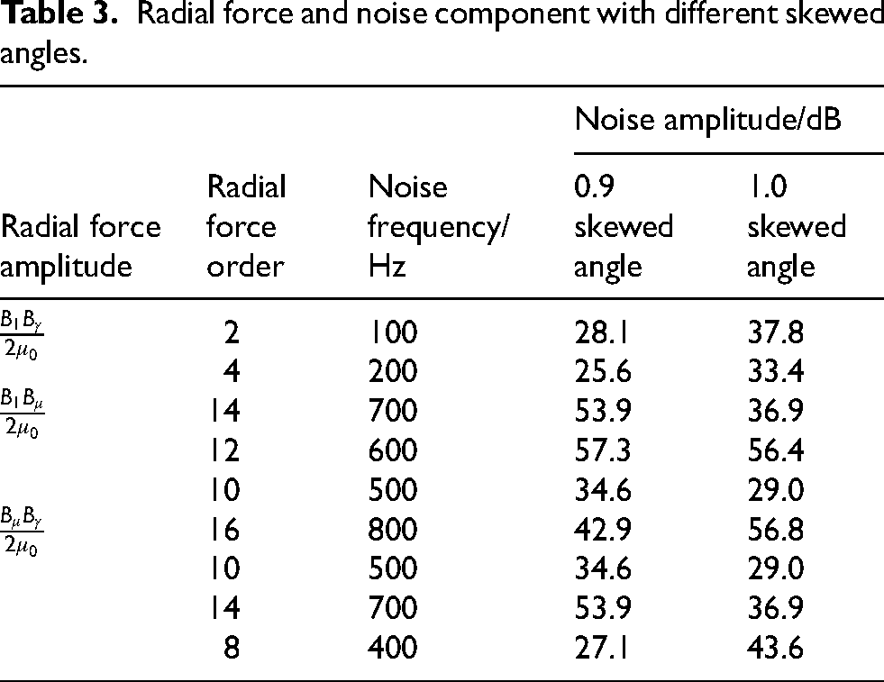
Since the parameter of skewed distance has a negligible effect on the fundamental magnetic field, its amplitude is assumed to be constant in two prototypes. Compared with the case of 1.0 skewed angle, the IM with 0.9 skewed angle has a lower amplitude of saturation harmonic according to 100 Hz or 200 Hz noise components, and a higher amplitude of the first-order slot harmonic according to 600 Hz noise component. The overall motor noise are 68.0 dB and 68.5 dB, respectively. Thus, the decrease in the saturation harmonics plays a more important role in the reduction of the magnetic noise. Furthermore, the negative effects due to skew are slightly relieved by adopting a smaller skewed angle. The dual skewed-rotor IM with 0.9 skewed angle has a better overall performance compared with the case of 1.0 skewed angle.
Conclusion
This study proposes a magnetic saturation model with axial variation to improve the calculation accuracy of the motor magnetic noise. The harmonics of flux density and radial force are analyzed with the 2D multi-slice model. The validity of the proposed saturation model is verified through coupled simulations and noise experiments. The main conclusions are as follows.
The degree of magnetic saturation depends on the relative position between the stator and the rotor of the motor. The saturation flux density and radial forces are almost sinusoidal at different axial positions of the skewed rotor. The spatial period is approximately the axial distance of one slot pitch. The fundamental magnetic field is less susceptible to the axial variation of the skewed rotor, but the average value of the saturation harmonic varies linearly with the skewed distance. The dual-skewed rotor with inverted structure can mitigate this amplitude variation. Under the same skewing design, the dual-skewed rotor brings in a greater proportion of saturation harmonic than the single-skewed rotor. The skewed distance of 0.9 slot pitch is verified as the optimal value to minimize the overall noise in dual-skewed rotor induction machines.