
Abstract
The flux density harmonics in the air-gap of AC machines have many origins. They generate electromotive forces and current harmonics, Maxwell forces, noise and vibrations. The principle of the presented method is to use a new auxiliary stator winding, connected to capacitors. The induced current harmonics generate flux density components in opposition to the initial ones, creating a damping effect. The study presented in this paper concerns an induction machine and particularly focus on flux density harmonics generated by slotting effects. The method allows to reduce the sound pressure level main lines of about 15 dBA. The vibrations are reduced too. Moreover the stator current harmonics are attenuated, and the power factor is significantly improved.
Introduction
Magnetic noise and vibrations of AC rotating machines come from flux density harmonics in the air-gap of the machine. Often, machines are noisy when they are fed by a PWM inverter which generates a lot of harmonics, but a machine can be noisy even when fed by sine voltages. A lot of previous works explain how to design a silent machine or how to reduce noise and vibrations using active reduction methods [1, 2, 3, 4]. This paper deals with a method to reduce flux density harmonics and noise using a damper circuit when the machine is fed by the electrical network. The main principle is to connect capacitors to a new three-phase auxiliary winding. In a first time, origins of flux density harmonics and magnetic noise in induction machines are reminded. Then the method will be presented, explaining how to design the damper circuit. Finally, some experimentations validate the procedure on an 11 kW induction machine under sinusoidal conditions.
Origins of noise and vibrations
Origins of harmonics in AC machines
The rotating field in the air-gap of AC machines is never perfectly sine, indeed flux density harmonics can be generated by several sources such as spatial distribution of the coils in a finite number of slots (space harmonics), variable thickness of the air-gap [1, 5, 6] (permeance harmonics), eccentricity [7], magnetic saturation or voltages harmonics due to the power supply [8].
The expression of the radial component
There is an infinity of flux density harmonics in the air-gap. Each of them generates an induced electromotive force (e.m.f.) at stator and rotor frames, which induces current harmonics and generates other flux density harmonics. Figure 1 shows the interaction between stator and rotor, and the generation of the flux density harmonics.
Interactions between stator and rotor.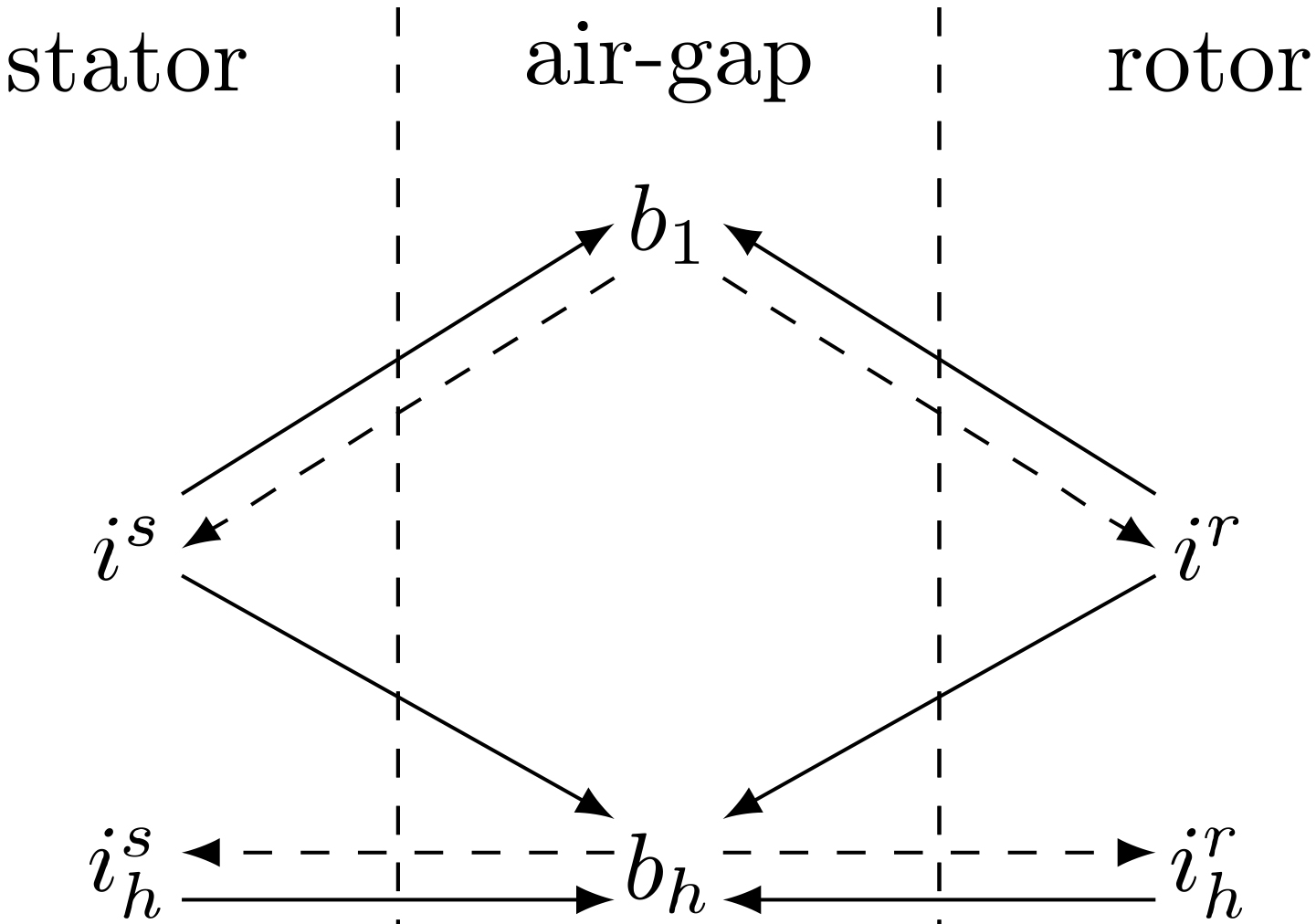
The stator current
A Several
Each flux density component induces in each conductor an electromotive force and so a current. Some
The flux density in the air-gap creates forces between stator and rotor. Three kinds of forces appear:
Tangential forces which create torque and rotor rotation. Magnetostrictive forces, negligible for rotating machines. Radial forces, expressed by the Maxwell relation. The radial component of the flux density
Because of the multiplicity of the flux density harmonics, many pressures waves occur and multiply the vibrations sources.
So non-stationary pressure components are expressed by:
Where
Supplementary stator winding and capacitors
This method needs an auxiliary stator winding. In the ideal case, it can be wounded in the same slots as the initial one, creating secondary stator coils similar to the initial stator ones. For example, Fig. 2 shows a classical three-phase winding with one pole pair and 4 slots per pole and per phase. The principle consists in creating another similar stator winding superimposed to the initial one, star or delta connected, in short circuit via three capacitors as shown in Fig. 3. The current in this auxiliary winding is noted
Three-phase winding with one pole pair and 4 slots per pole and phase.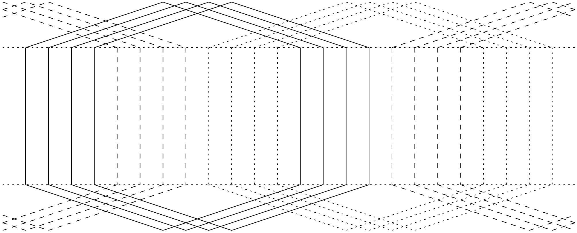
Representation of the machine with auxiliary windings.
The flux density fundamental induces a current in the auxiliary windings at the same frequency than the stator. For this low frequency, the capacitors have a high impedance, so the induced currents are small and don’t disturb the machine torque.
The equivalent single-phase diagram relative to the fundamental variables is presented in Fig. 4 where
Compared to the classical equivalent diagram of an induction machine, a new auxiliary branch appears with the capacitor
Equivalent single-phase diagram.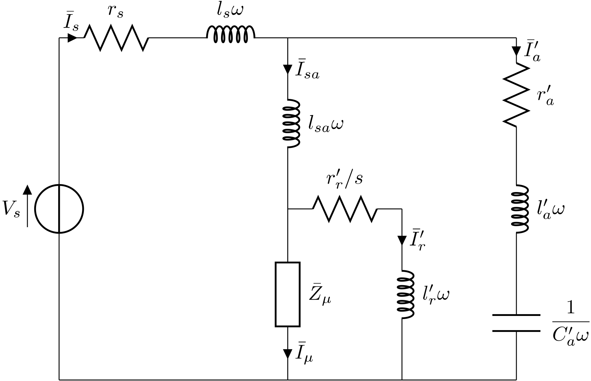
The flux density components induce current harmonics in the auxiliary windings. For the high frequency harmonics, these induced currents can easily circulate and generate flux density components in opposition to those which create them, according to the Lenz law. However, the created components must have the same polarity than the original ones. Figure 5illustrates the phenomena.
Interactions between stator, rotor and auxiliary windings.
The
Equivalent single-phase diagram for the harmonics.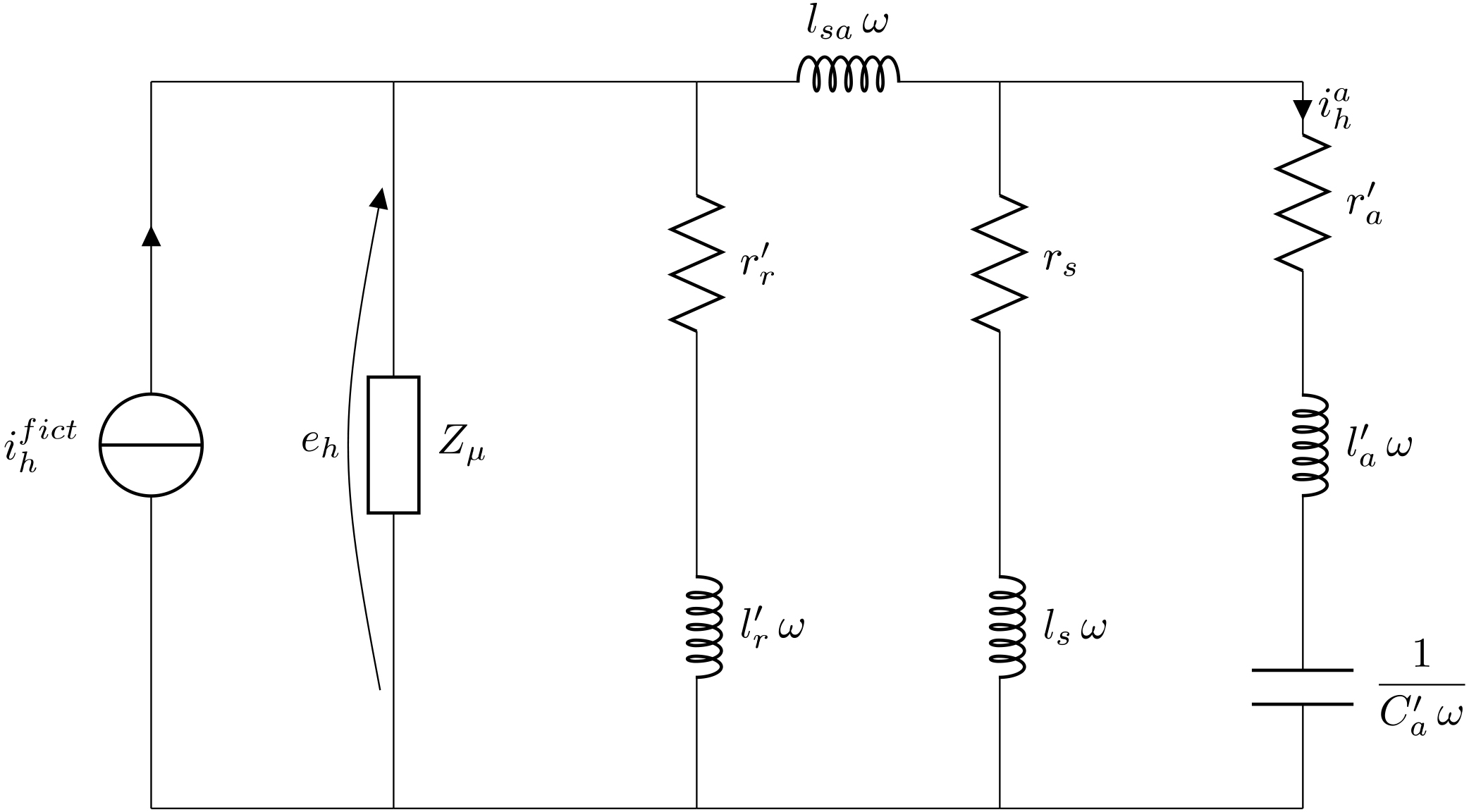
The auxiliary branch creates an important damping effect because the value of
The best value of the capacitors depends on the inductances values. A large range of capacitors values is suitable: if the resonance frequency is slightly below the unwanted frequencies, the impedance of the auxiliary branch will be small for a large frequency range.
Used machine
The used induction machine has the following characteristics: 11 kW – 50 Hz – 380/660 V – 23/13A –
The theoretical analysis [1, 3] shows that flux density harmonics exist at the frequency
The magnetic noise and vibrations, due to the Maxwell forces, are essentially due to the combination of those harmonics with components at the supply frequency. So, according to Eq. (3), magnetic noise and vibrations exist at frequencies near to 700 Hz, 800 Hz, 900 Hz, 1500 Hz, 1600 Hz, 1700 Hz, 2300 Hz, 2400 Hz, 2500 Hz, etc. The acoustic spectrum shows important noise components at 800 and 900 Hz, in accordance to the theory; this is shown in Fig. 7 where the acoustic pressure is measured with a microphone at 1 meter. The global level is 74.8 dBA at no-load. There is no auxiliary winding in this machine but all the windings connections are accessible outside the machine. As there are 4 slots per pole and per phase, it was decided to use an half of the windings (2 slots per pole and per phase) to supply the machine by the network, and the other half as auxiliary windings.
Acoustic pressure level of the no-load machine at 1 meter.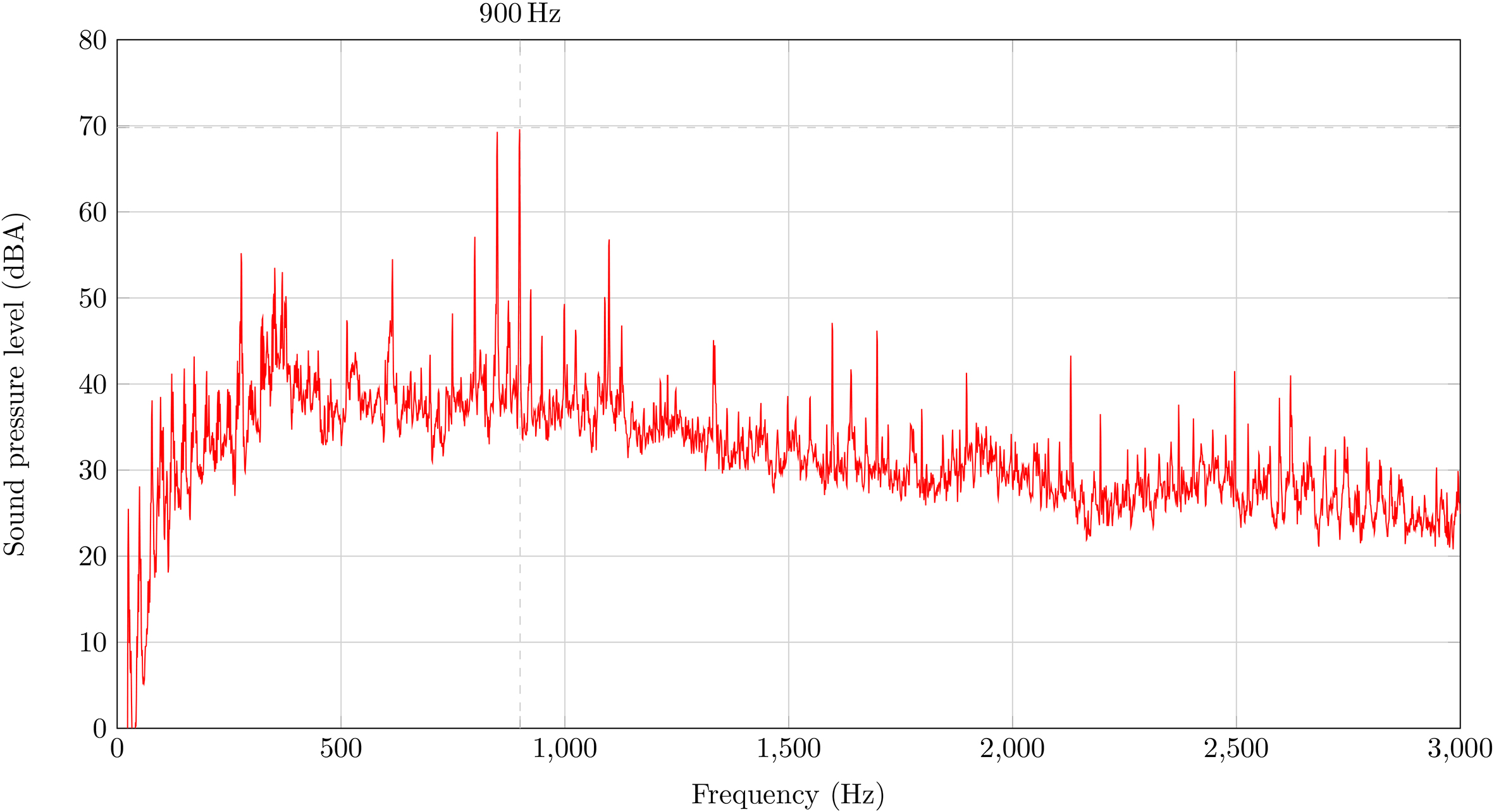
As only half of the windings is connected to the supply (star), the 50 Hz phase to phase voltage
Induced e.m.f. at the free winding (2 slots per pole and phase).
Three 120
Acoustic pressure level of the no-load machine at 1 meter, with three 120 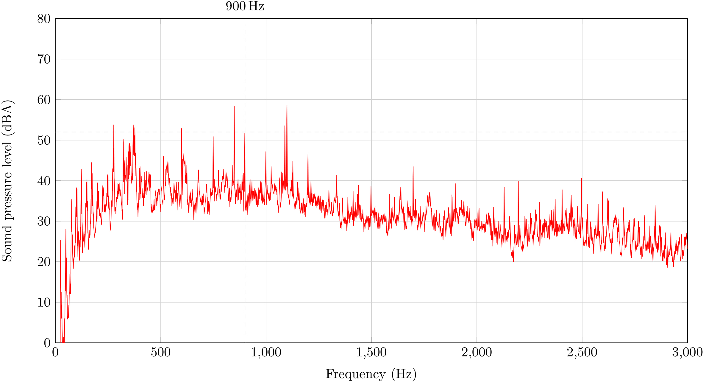
Stator current spectrum without and with capacitors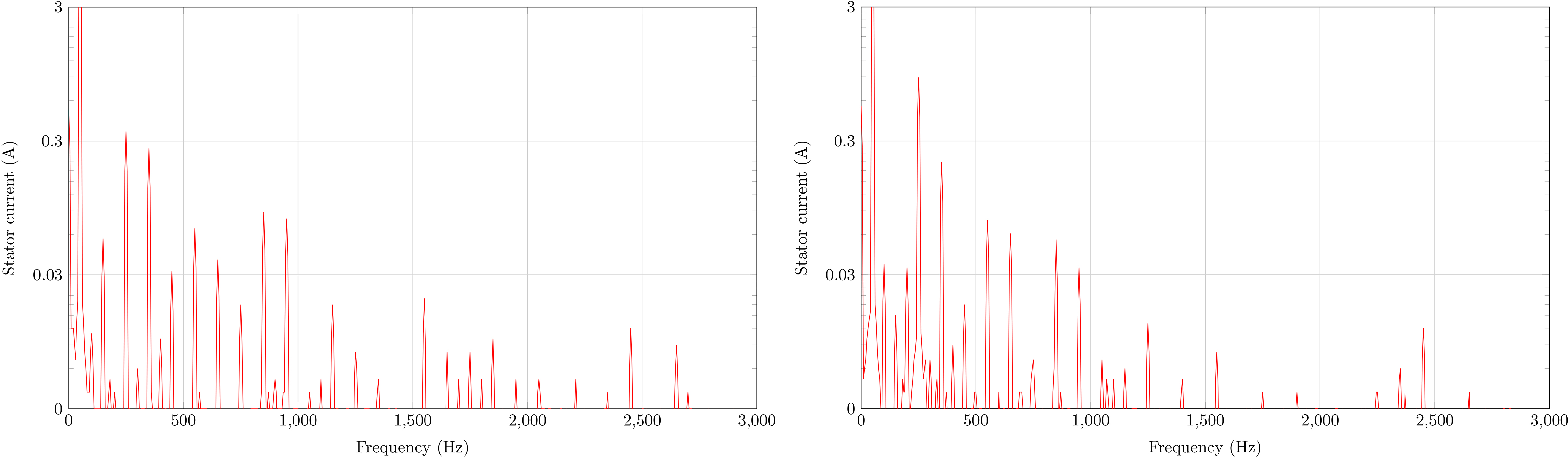
The vibrations are measured too with an accelerometer placed on the stator, which confirm the acoustic measures: the vibrations at 800 and 900 Hz decrease respectively from 0.104 and 0.965 m.s
Influence on the power factor
Without capacitors, the machine requires a reactive power
In order to minimize the stator current and to maximize the power factor of the studied machine where
As the flux density harmonics are mitigated by the auxiliary windings and the capacitors, the induced e.m.f. and the stator current harmonics are mitigated too; except for the line at 250 Hz. This is illustrated by Fig. 10 which shows the supply current spectrum without and with capacitors. As the torque harmonics are in relation to the flux density harmonics, they can be reduced too.
Conclusion
It is usual to connect some capacitors in order to compensate the reactive power absorbed by induction machines. Another possibility is to connect capacitors on a new auxiliary three-phase winding which can be wounded into the same slots than the initial windings. By this way, the power factor of the machine is improved and the stator current harmonics are attenuated. Moreover, this damper circuit considerably mitigate flux density harmonics in the air-gap, reduce noise and vibrations, and can attenuate stator current harmonics.
The drawback is to design the stator of the machine with supplementary windings, but those one can be small. No electronic is used and the damping effect is permanent.
Footnotes
Acknowledgments
This work has been achieved within the framework of CE2I project (Convertisseur d’Energie Intégré Intelligent). CE2I is co-financed by European Union with the financial support of European Regional Development Fund (ERDF), French State and the French Region of Hauts-de-France. The authors would like to thank SATT Nord-de-France (Société d’Accélération du Transfert de Technologie) that has patented this invention .