
Abstract
Currently, there are a series of problems such as insufficient power, short range, and low operating efficiency of commercially available electric microtillers in mountainous and hilly areas, and this paper proposes a three-port power converter design for electric microtillers based on a hybrid energy storage system. The design adopts a hybrid energy storage structure of lithium batteries and supercapacitors, a dual closed-loop controller and a three-port power converter, which ensures the voltage stability of the system during load fluctuations. To further reduce the cost of tillage, a combination of photovoltaic power generation and three-port power converter is used to realize the efficient management of energy flow between the photovoltaic module, energy storage module, and motor. During the tillage process, the three-port power converter can provide feedback adjustment for different depths and changes in soil hardness based on field test data. Through simulation and experiment, the high efficiency and stability of the three-port power converter and its application feasibility and application prospect are verified.
Keywords
Introduction
More than 30% of China’s arable land is located in hilly and mountainous counties, which are important production areas for grains, fruits, and vegetables, yet the level of mechanization is only 46.87%, which is 33.87% lower than that of the plains, 1 which hinders the development of China’s agricultural modernization. Promoting agricultural mechanization is an effective way to improve this situation, 2 and the use of agricultural machinery can help solve production difficulties such as the shortage of fertilizers, labor, and water. 3 However, hilly and mountainous areas have complex and varied terrain, small and scattered plots of land, and there are no supporting mechanized roads, which leads to high operating costs for large and medium-sized agricultural machinery, 4 and the operation of heavier and larger machinery in hilly areas is easily restricted by their terrain 5 . Compared with large-sized machines, small-sized agricultural machines with strong flexibility are more suitable for hilly areas, which is the key to increase the rate of agricultural mechanization in hilly and mountainous areas. 6
The wide application of small agricultural machines in hilly and mountainous areas has helped to significantly improve the efficiency of agricultural production in hilly areas. As a typical small-scale agricultural machine, the microtiller is one of the main equipment to improve the efficiency of agricultural production in hilly and mountainous areas. However, most of the microtillers in the current market still rely on traditional fuel drive, and although this type of microtiller meets most of the operational needs in terms of power output, there is still much room for improvement in terms of energy consumption and environmental impact. And with the rising price of fossil fuels such as diesel, the economy of fuel-fired microtillers is also facing challenges. 7 Therefore, how to make microtillers more environmentally friendly and economical has gradually become the focus of research.
Against this background, electric microtillers, which are characterized by low energy consumption and zero emissions, are receiving more and more attention in agricultural applications. Compared with traditional fuel-driven microtillers, electric microtillers produce significantly less noise and vibration during operation, which not only improves the operating comfort of the agricultural machine but also reduces the impact on the environment. Especially in the current global energy structure to clean energy transition trend, electric micro-tiller has the potential to comply with the future direction of agricultural machinery development, can meet the needs of agricultural production at the same time, to promote the green transformation of agricultural machinery. 8
However, despite these advantages of electric microtillers, they still face a number of challenges in practical applications. First, existing electric microtillers have limited range in high-load farm operations. Due to the limitations of battery technology, the limited battery capacity is often difficult to support prolonged high-load operations. 9 Energy storage devices usually require high energy density and high power density to ensure both range and power performance. Energy-based energy storage components represented by lithium-ion batteries have the advantages of high energy density and stable output voltage, but high multiplicity charging and discharging will lead to its capacity and life decay; power-based energy storage devices represented by supercapacitors have excellent multiplicity performance, but low energy density, which is difficult to meet the demand for range. Studies have shown that in the continuous cultivation process of farmland, the battery power of electric equipment is often consumed in a short period of time, which seriously affects its operational efficiency. Second, most of the electric microtillers currently on the market are designed with fixed power output, lacking multi-mode power output adjustment. Under different operating environments, such as facing different soil hardness and terrain conditions, fixed power cannot meet the operational requirements, especially under the conditions of harder soil, the low power output of the electric microtiller will lead to poor operational results, or even unable to plow.
To address these problems, a hybrid energy storage three-port power converter for electric microtiller is designed in this paper. The hybrid energy storage device forms an ideal energy storage device by combining the above two types of energy storage elements, thus combining the advantages of different types of energy storage elements. The three-port power converter is designed to realize real-time adjustment of the output power according to the load changes. A hybrid energy storage three-port power converter is designed to be applied to electric microtillers after in-depth research and field tests on the operating effect in complex terrain. According to the characteristics of the electric microtiller, the energy storage part of the design adopts the hybrid power design of supercapacitor and lithium battery.
We selected the second-order RC models for both lithium batteries and supercapacitors because they provide a good balance between accuracy and computational cost. They are well-suited for capturing the dynamics of these energy storage devices in various applications, and can be used for real-time simulation and control.
For lithium batteries, the second-order RC model is a widely accepted and validated model that captures the dynamic behavior of the battery. This model includes two RC branches to represent the electrochemical and diffusion processes within the battery.
For supercapacitors, the second-order RC model is also a suitable choice. This model can capture the supercapacitor’s behavior, including its high capacitance and rapid charging/discharging characteristics.
Alternative models for lithium batteries and supercapacitors include: (1) Electrochemical Models: These models provide a detailed representation of the electrochemical processes within the battery or supercapacitor. While they offer high accuracy, they are often computationally intensive and may not be suitable for real-time simulation and control applications. (2) Higher-Order RC Models: These models can provide even higher accuracy than second-order RC models, but they also increase the computational cost and complexity. (3) Simplified Models: Simplified models, such as first-order RC models or equivalent circuit models, may be less accurate but have lower computational costs.
Contributions
The proposed three-port power converter design for electric microtillers based on a hybrid energy storage system offers several key contributions: • The Hybrid Energy Storage System combines lithium batteries and supercapacitors to provide a high power density and long cycle life, enabling the electric microtiller to operate for extended periods and handle demanding loads. It provides redundancy and fault tolerance, ensuring that the system remains operational even in the event of component failure. • Three-Port Power Converter enables efficient management of energy flow between different sources and loads, including the photovoltaic module, energy storage module, and motor. It provides flexibility and scalability, allowing for easy integration of additional energy sources or loads. • Dual Closed-Loop Controller ensures voltage stability during load fluctuations, providing a stable power supply to the motor and other components. It improves the dynamic response of the system, enabling it to quickly respond to changes in load and operating conditions. • Photovoltaic Power Generation utilizes photovoltaic power generation to reduce energy costs and increase sustainability, providing a clean and renewable source of energy. It can reduce energy costs by generating electricity during periods of low load or when the energy storage system is fully charged.
The remainder of this paper is organized as follows. Section 2 presents Background; Section 3 presents the proposed design; Section 4 demonstrates simulations and experiments are. Section 5 summarizes the paper.
Background
Comparison among recent literature and proposed work.
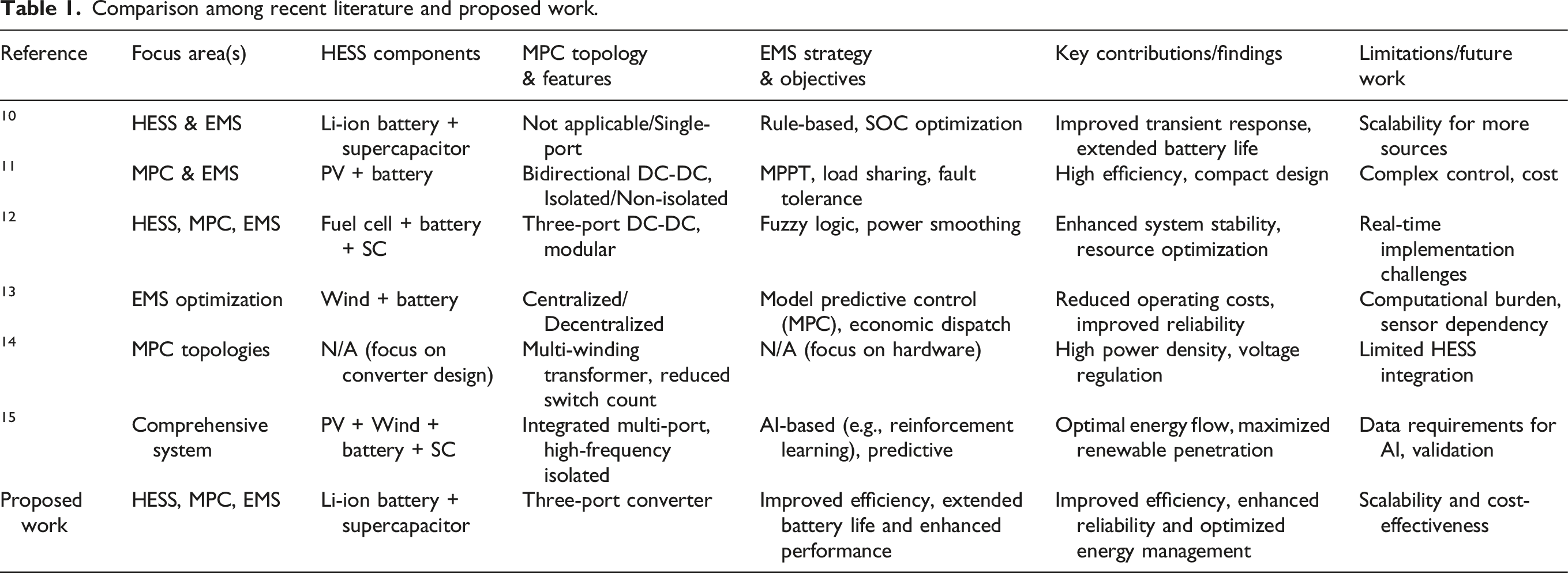
The proposed work aims to design a HESS with a three-port converter and an EMS that optimizes efficiency, extends battery life, and enhances performance. By integrating Li-ion batteries and supercapacitors with a three-port converter, the system can achieve improved efficiency, reliability, and optimized energy management. The proposed work also aims to address the scalability and cost-effectiveness of the system, making it a viable solution for renewable energy applications.
Combining the advantages of high power density supercapacitors to cope with transient load changes16,17 and high energy density lithium batteries to provide stable power for a long period of time,
18
the system is designed with a dynamic power distribution design between lithium batteries and supercapacitors. Based on the dynamic characteristics of the designed electric microtiller, a second-order RC model of the lithium battery is adopted (as shown in Figure 1). Compared to the basic Thevenin model,19,20 this model improves control accuracy to ±1% while effectively adapting to diverse dynamic operating conditions of the electric microtiller. Second-order RC model for lithium battery.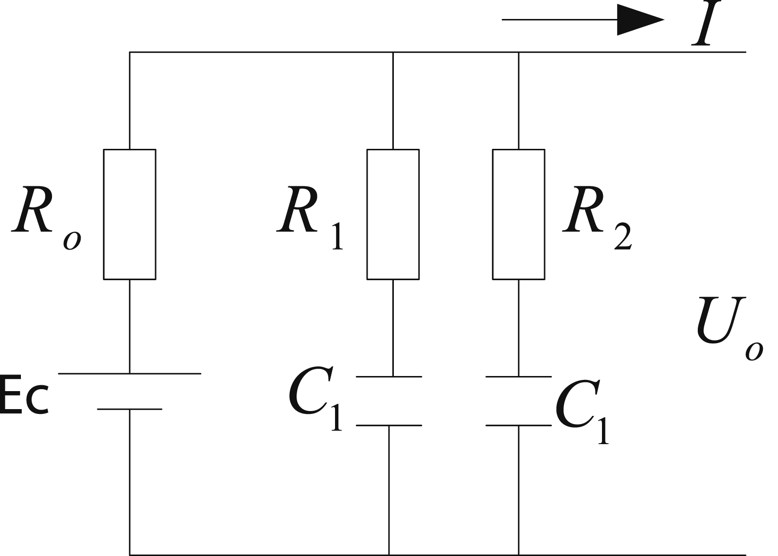
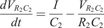
The dynamic of the second-order RC model is presented as
A third-order RC configuration is adopted in the supercapacitor RC network model, effectively balancing the accuracy and real-time performance requirements of the supercapacitor system (Figure 2). Supercapacitor RC network model.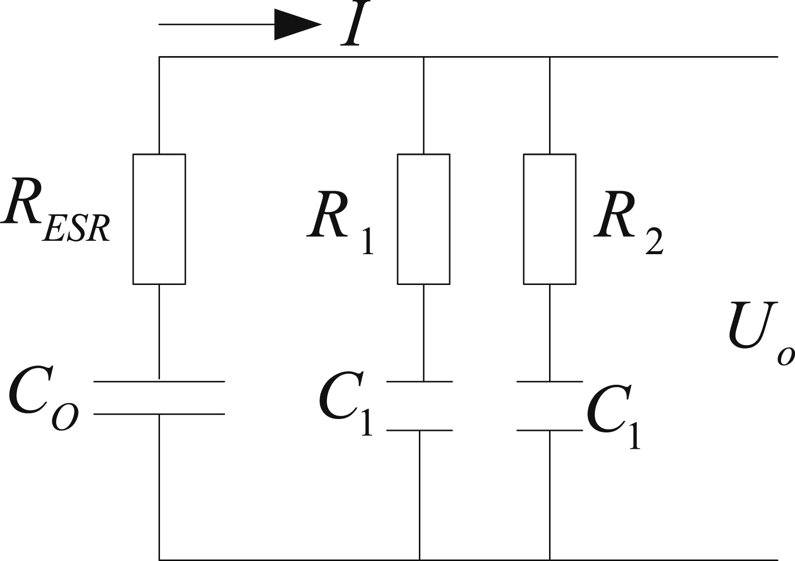
Its dynamic is presented as follows

In addition, through the photovoltaic charging module, solar energy is utilized to provide range protection for the electric microtiller. To ensure the safe operation of the system, overcurrent protection, temperature protection and blocking protection are designed. Studies have shown that hilly and mountainous areas tend to have sufficient light resources, and the higher altitude and higher temperature in mountainous areas enable the energy conversion efficiency of PV panels to reach a high level under these conditions. 21 In addition, the solar energy potential in hilly areas is huge, 22 and if this clean energy can be fully utilized as an auxiliary energy source for electric microtillers, the range of electric microtillers can be significantly improved and the over-reliance on battery capacity can be reduced. 16 The proposed scheme integrates a photovoltaic (PV) power generation system into an electric micromillow 23 as an auxiliary energy source for its power system. By providing continuous power to the electric microtiller through the photovoltaic power generation system, it not only extends the operating time but also enhances the operating hours of the electric microtiller without increasing the battery capacity. The design of multiple circuit protection effectively avoids overload, short circuit, and other faults.
A hybrid energy storage three-port power converter designed in this paper that can be applied to an electric microtiller has the following three advantages: (a) Efficient. The hybrid power supply’s dynamic power distribution quickly delivers the high power output needed when the motorized microtiller goes into complex terrain or harder soils,
24
ensuring that the equipment operates without voltage drops and that the energy output is highly efficient. (b) High reliability. The supercapacitor can absorb the inrush current through dynamic power distribution in case of sudden load change of the electric microtiller, effectively reducing the load of the lithium battery and avoiding its over-discharge. When the load is light or during continuous operation, the system switches to the Li-ion battery to provide the main power, and the ultracapacitor is recharged at the same time.25,26 (c) Strong range. The solution is equipped with a photovoltaic charging module and combines Maximum-Power Point-Tracking (MPPT) technology27,28 and Proportional-Integral-Derivative (PID) control technology.
29
This reduces the dependence on traditional charging methods for electric microtillers and increases their range.
Proposed design
Electric microtiller three-port power converter working principle
An electric microtiller consists of a mechanical part and an electrical part. The proposed scheme in this paper mainly involves the energy storage unit and the three-port converter power converter in the electrical part of the electric microtiller. Three-port converter circuits are ideal for connecting renewable energy sources, energy storage units, and loads in new energy generation systems, and they have the advantages of small size, fewer components, and unified energy flow management between ports, which can reduce the size and mass of the system and lower system losses. Three-port converters can be categorized into isolated three-port converter circuits and non-isolated three-port converter circuits, which are used in the proposed strategy. Three-port converter circuits are non-isolated. The block diagram of the three-port power converter circuit of the electric microtiller hybrid energy storage device is shown in Figure 3, which mainly includes a solar power panel, boost circuit, DC-DC regulator circuit, lithium iron phosphate battery, super capacitor, power control circuit, energy management system, voltage sensor, current sensor, and motor. The solar panel generates electricity through boost and then stabilizes the voltage, charges the Li-ion battery and super capacitor, and then sends it to the power control circuit through the boost circuit to provide electricity to the motor according to the change of the tillage load. The current sensor detects the signal of the motor’s tillage load change and sends it to the energy management system, which controls the working mode of the Li-ion battery and super capacitor. The voltage sensor detects the power of the lithium battery and super capacitor and sends the signal to the energy management system to realize the charging control of the hybrid energy storage device. The energy management system is the center of the whole control system, which outputs Pulse Width Modulation (PWM) signals to control the boost circuit, DC-DC regulator circuit, and power control circuit, and ultimately realizes the functions of output power self-regulation control and multi-functional protection. Electric micro-tiller control block diagram.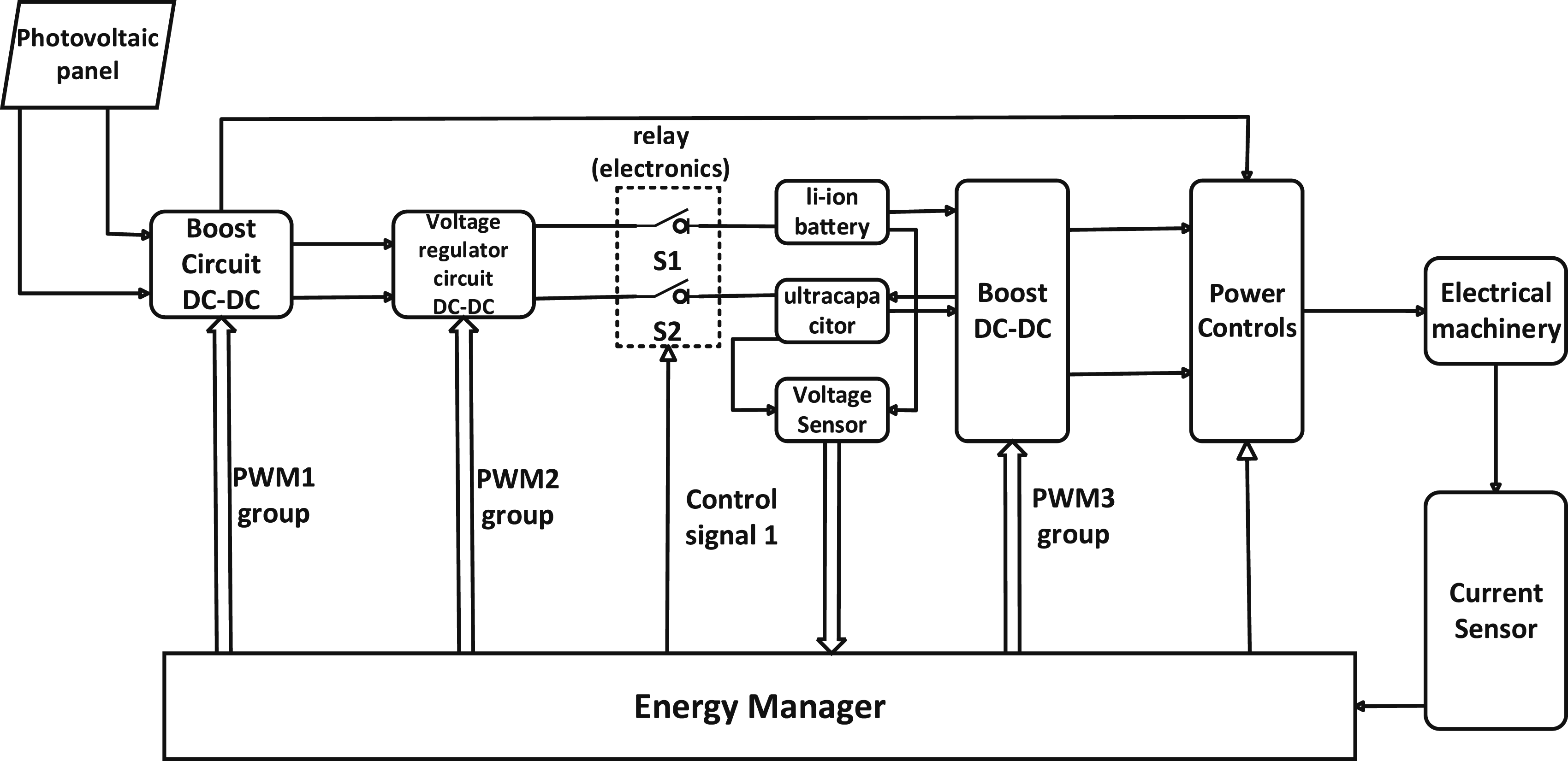
Three-port power converter structure
The three-port power converter mainly consists of a voltage closed-loop controller, a current closed-loop controller, power circuits, and output capacitors and load-side circuit breakers. The current closed-loop controller adopts single closed-loop control to realize precise control of output current. The voltage closed-loop controller, on the basis of the current closed-loop controller, constitutes a double closed-loop structure by applying voltage closed-loop control in order to realize the stabilization of DC bus voltage. Lithium battery belongs to energy-type energy storage device, through the current closed-loop controller for its input and output power control. Supercapacitor belongs to the power type energy storage device, and its function is to ensure that the output voltage V
o
is stable. Since the load side adopts the parallel connection structure, it only needs to control the output current of the energy storage device I2 to realize its output power P2 control (P2 = V
o
× I2). The schematic diagram of the three-port power converter circuit of the hybrid energy storage device of the electric microtiller is shown in Figure 4, in which part a of the circuit structure maintains the stability of the output DC bus voltage, and part b realizes the precise output of the power of the energy-based energy storage element. Three-port power conversion circuit.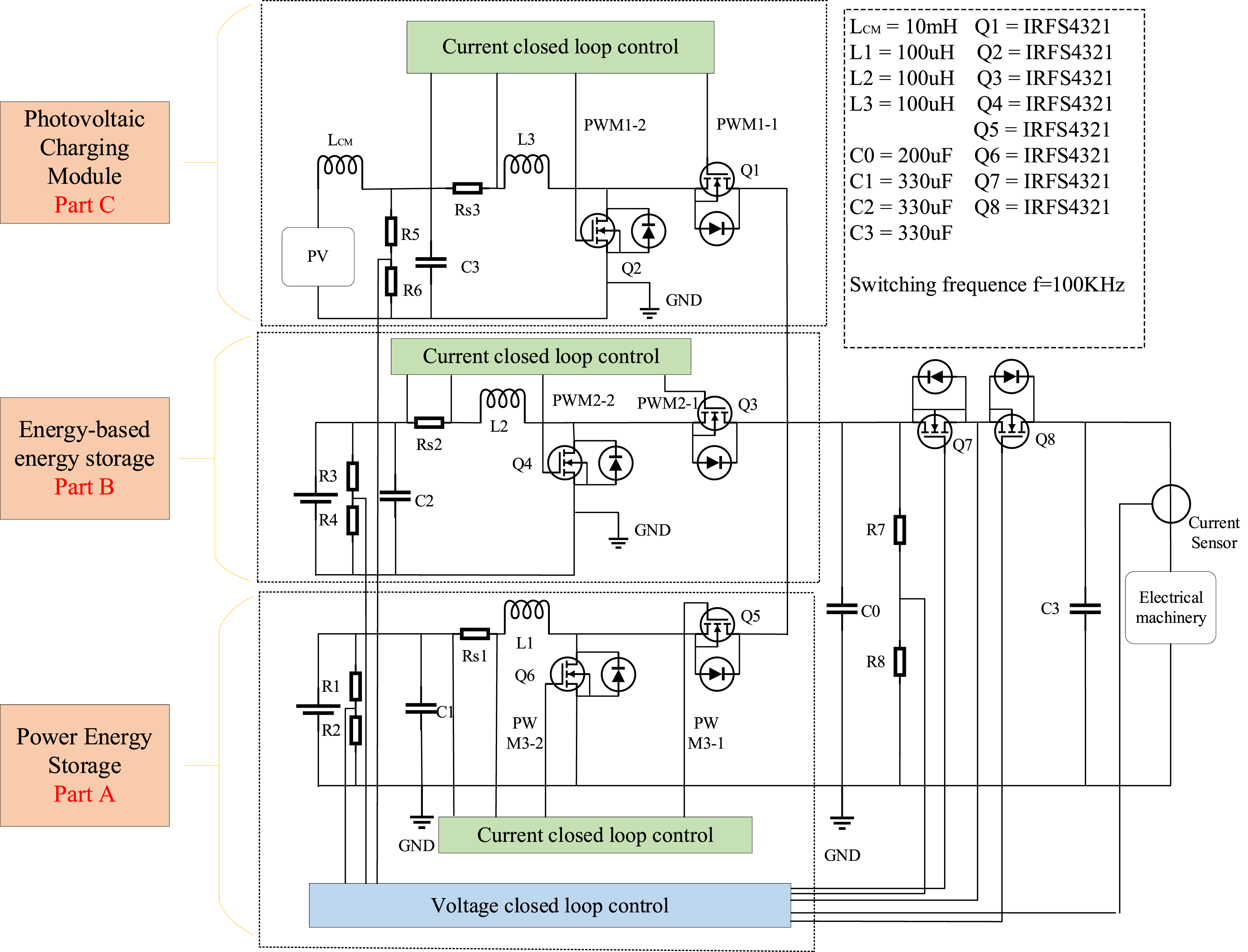
To enhance electromagnetic compatibility in the non-isolated topology, a common-mode inductor (LCM) and filtering capacitors (C0, C1, C2, C3) are integrated into the power circuits. The common-mode inductor suppresses high-frequency noise generated by switching devices, while the capacitors mitigate voltage ripple on the DC bus.
Three-port operating modes.
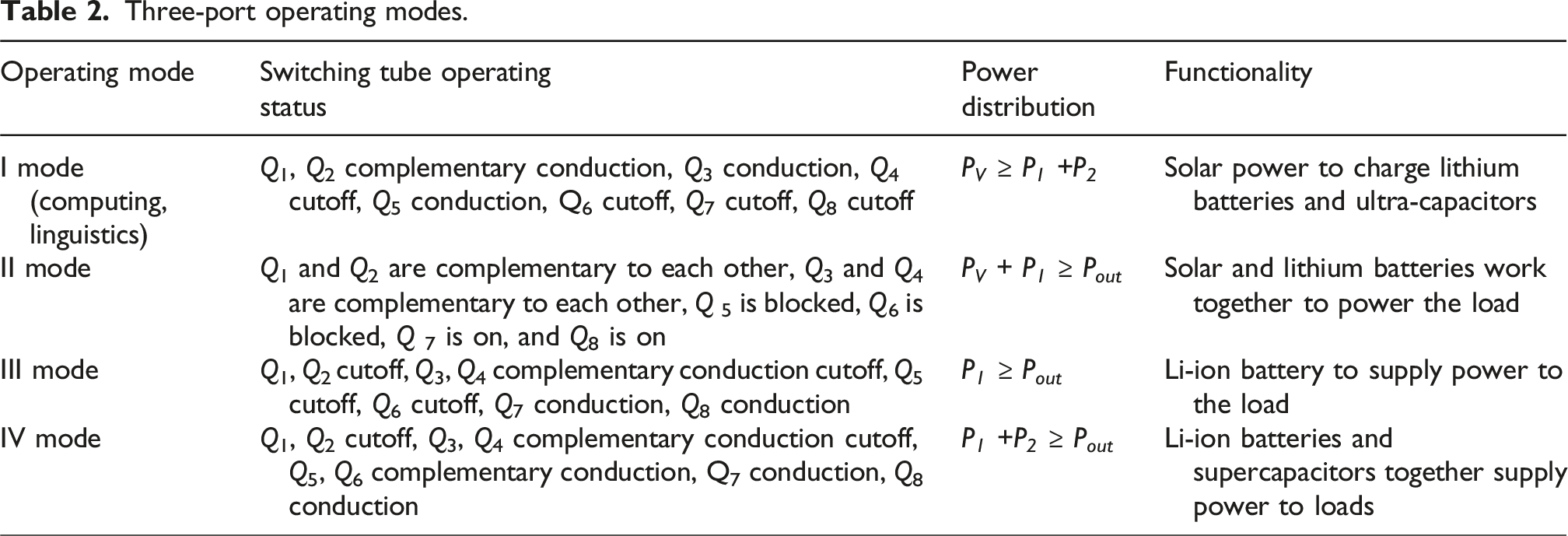
Ⅰ: charging mode, by solar power through boost and then through the power control on the lithium battery and supercapacitor power supply, this mode of operation is referred to as Ⅰ mode, as shown in Figure 5(a). Operating mode. (a) Operating mode Ⅰ, (b) Operating mode II, (c) Operating mode III, (d) Operating mode Ⅳ.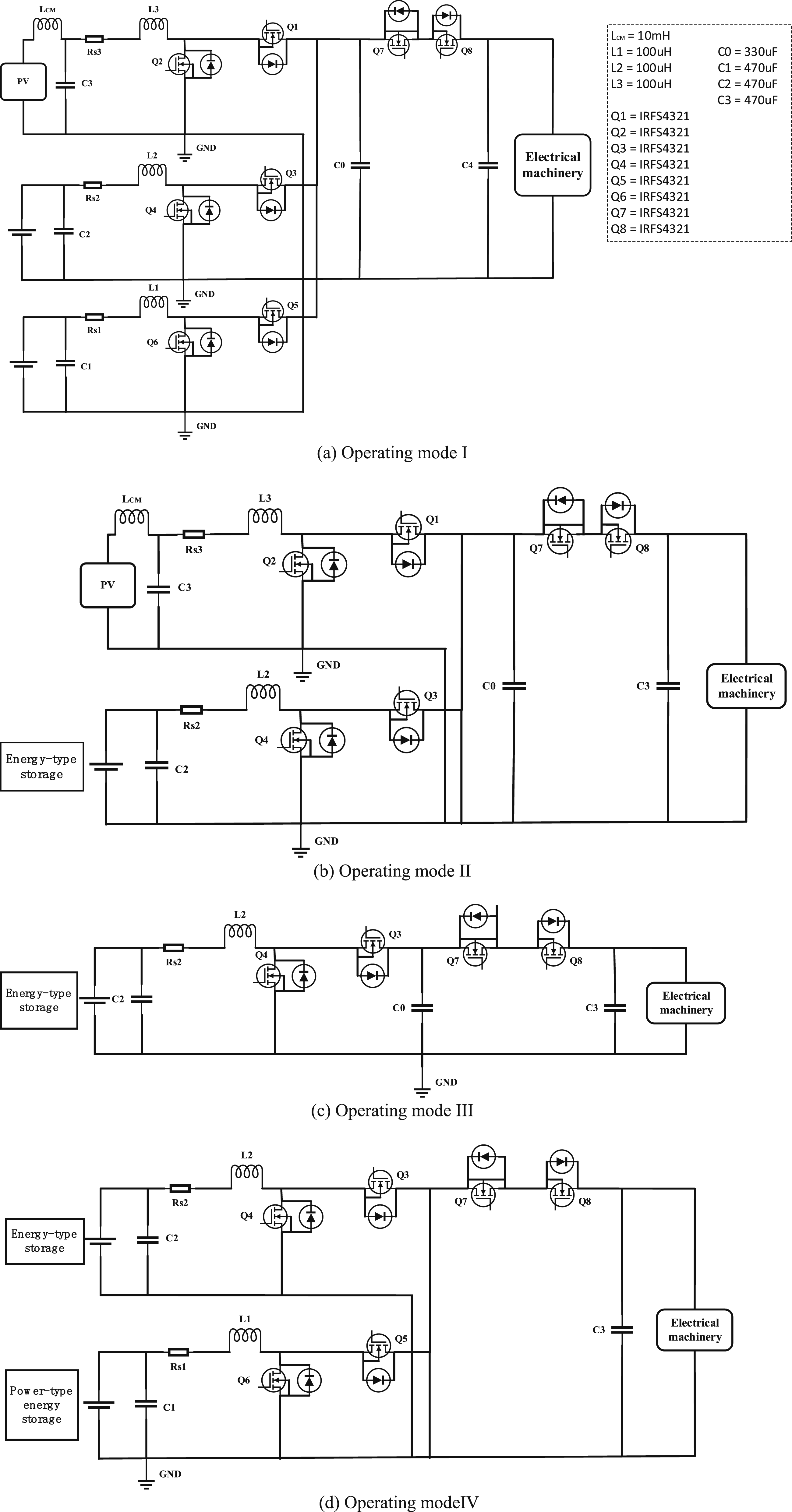
Ⅱ: When the solar power generation power PV is small and cannot meet the load power requirements, if PV + P1 ≥ Pout when, then the solar power generation device and energy-based energy storage device together to provide power to the load, the three-port converter operates in the Ⅱ mode, as shown in Figure 5(b).
III: When PV = 0 and the solar power generation is negligibly small, If P1 ≥ Pout the power is supplied to the load by the energy-based storage device, the three-port converter operates in the III mode as shown in Figure 5(c).
Ⅳ: When PV = 0 , need load demand power is larger, by the energy-based energy storage device and power-based energy storage device together to provide energy to the load, the three-port converter works in Ⅳ mode , as shown in Figure 5(d).
To ensure coordinated operation between the lithium battery and supercapacitor, the matching relationship between the C-rate limitation of the lithium battery and the current is defined as
To address the power distribution issue of the hybrid energy storage system in electric microtillers, this study adopts a three-port converter (TPC) topology where the lithium-ion battery, supercapacitor, and load are hybrid-connected through a multi-port power converter. Based on this topology, a control system is proposed where the energy-type storage device (lithium-ion battery) employs current closed-loop control, and the power-type storage device (supercapacitor) employs voltage closed-loop control, as shown in Figure 5(d). In the dual-input single-output mode, while ensuring the stability of the bus voltage, a droop control strategy is implemented. The energy state information of the lithium battery and supercapacitor at each TPC module is introduced into their corresponding droop coefficients. This allows the droop coefficients of each TPC output to automatically adjust based on the energy state of the lithium battery and supercapacitor, ensuring that the TPC output power is always proportional to the maximum utilization of the lithium battery and supercapacitor output power. Additionally, this approach automatically balances the state of charge (SOC) of each energy storage device, achieving precise power distribution between the power-type and energy-type storage devices.
In the modular TPC system with a common load bus, the droop control coefficient model for each TPC output is as follows
Voltage adjustment coefficients for the lithium battery and supercapacitor terminals are defined as
Based on the control principle analysis in Figure 5(d) and the droop control theory, the relationship between the output current of any parallel module and the energy-coordinated droop coefficient is derived as
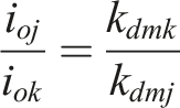
From the above equations, the ratio of output currents between any two modules in the system is inversely proportional to their energy-coordinated droop coefficients. Specifically, a smaller energy-coordinated droop coefficient results in a larger output current and power for the corresponding module. This energy-coordinated droop control strategy ensures precise power distribution between the lithium battery and supercapacitor.
When there is overcurrent in the motor, Energy Manager sends out a low level signal to turn off Q 7, cutting off the motor power supply line to protect the motor. When the operation is normal, the energy manager sends out a high level signal and Q 7 is turned on.
When the electric microtiller is working, the rotor position and speed information collected by the motor Hall sensor from to is transmitted to the driver through the Hall signal line. According to the received Hall signal, the driver outputs a pulse square wave signal with a duty cycle of 50% and an amplitude of 5 V through the driver speed feedback port and transmits it to the STM32 microcontroller. After the STM32 microcontroller acquires this square wave signal, it reads the frequency of the signal by using the input capture mode (rather than the external interrupt mode), and according to the driver’s speed calculation formula:
Based on the motor’s electromagnetic torque equation, when the microtiller is in operation and encounters harder soil or greater resistance, the motor will need to provide more torque to maintain speed or output power, which will result in an increase in current I, which increases input power and motor heating. From this, the instantaneous power expression can be introduced from the current and voltage. Based on the input power and losses, a relationship can be derived for the instantaneous output power. The instantaneous input power is
The instantaneous output power is
For the different conditions of the cultivated land, the principle is illustrated with two common different operating modes to adapt to the different power requirements of different terrain.
Operating mode III: If P1 ≥ Pout, the power is supplied to the load by the energy-based storage device, and the three-port converter operates in mode III, when the maximum power of a single battery is available
If
Working Mode Ⅳ: If encountering hard soil, knot or high power demand, this time the lithium battery and supercapacitor power supply together, so as to achieve the purpose of breaking the soil and so on. If
In terms of connection mode, the supercapacitor and lithium battery are connected in parallel. The lithium battery is responsible for providing long-term stable energy output, while the supercapacitor is used to meet the instantaneous high power demand, especially during startup or load surge, and can dynamically adjust the power distribution under different operating conditions through real-time control of the three-port converter to ensure efficient operation and prolong the battery life.
Energy management control strategy
In the above modal work, the energy management system accurately regulates the whole system by real-time acquisition of the bus voltage, the terminal voltage and current data of the solar power generating end, the supercapacitor and the lithium battery, combined with the PID control algorithm. The system adopts a dual closed-loop control structure to realize fast response and precise control. The dual closed-loop control strategy improves the stability of the output voltage by simultaneously regulating the internal and external circuits. Not only that, by optimizing the design of the boost circuit, it improves the stability of the system during transient load changes and ensures that the DC bus voltage always stays within the set stability range.
To quantitatively link the motor power dynamics (7) and (8) under the dual-loop control scheme, the DC bus voltage fluctuation is constrained to 48 V ±5% under load variations. In the Voltage outer loop, the bus voltage Vbus is regulated to track the reference Vref = 48. The allowable voltage deviation is
The single battery mode, dual battery mode high power regulation method is by adjusting the duty cycle of the PWM wave by increasing the ratio by only 1% each time until the desired speed level is reached or the duty cycle of the PWM wave reaches the threshold value. At this point, maintaining the stability of voltage and current is very critical to the response speed of the system. In the Li-ion battery + supercapacitor mode, a double closed-loop control structure with voltage outer loop and current inner loop is used to control the size of the supercapacitor discharge current. This control strategy, combined with the designed three-terminal power-port power conversion circuit for hybrid energy storage, proposes to utilize the voltage deviation obtained from the voltage loop calculation, and then calculate the current loop reference value. The current loop obtains a suitable compensation current based on this reference value, and the compensation value is obtained through transfer function transformation, thus realizing the control of the discharge current. This control method is not only conducive to the protection of the energy storage device, but also ensures that the device provides a high power discharge when needed to satisfy the high current requirement needed in a short period of time, thus realizing the function of increasing the power and maintaining a stable rotational speed. Therefore, two power distribution control methods are investigated in this paper, one for current-based control and one for voltage-based control.
Current-based control
In the hybrid energy storage system, the battery operating voltage does not float much, and the supercapacitor works in a wide voltage range, controlling the current at the battery side can better control the power at the battery side, and the supercapacitor side automatically balances the system power. As shown in Figure 6 is the control block diagram of converter current type power distribution applied to hybrid energy storage system. Control block diagram of converter current-based power distribution under hybrid energy storage system.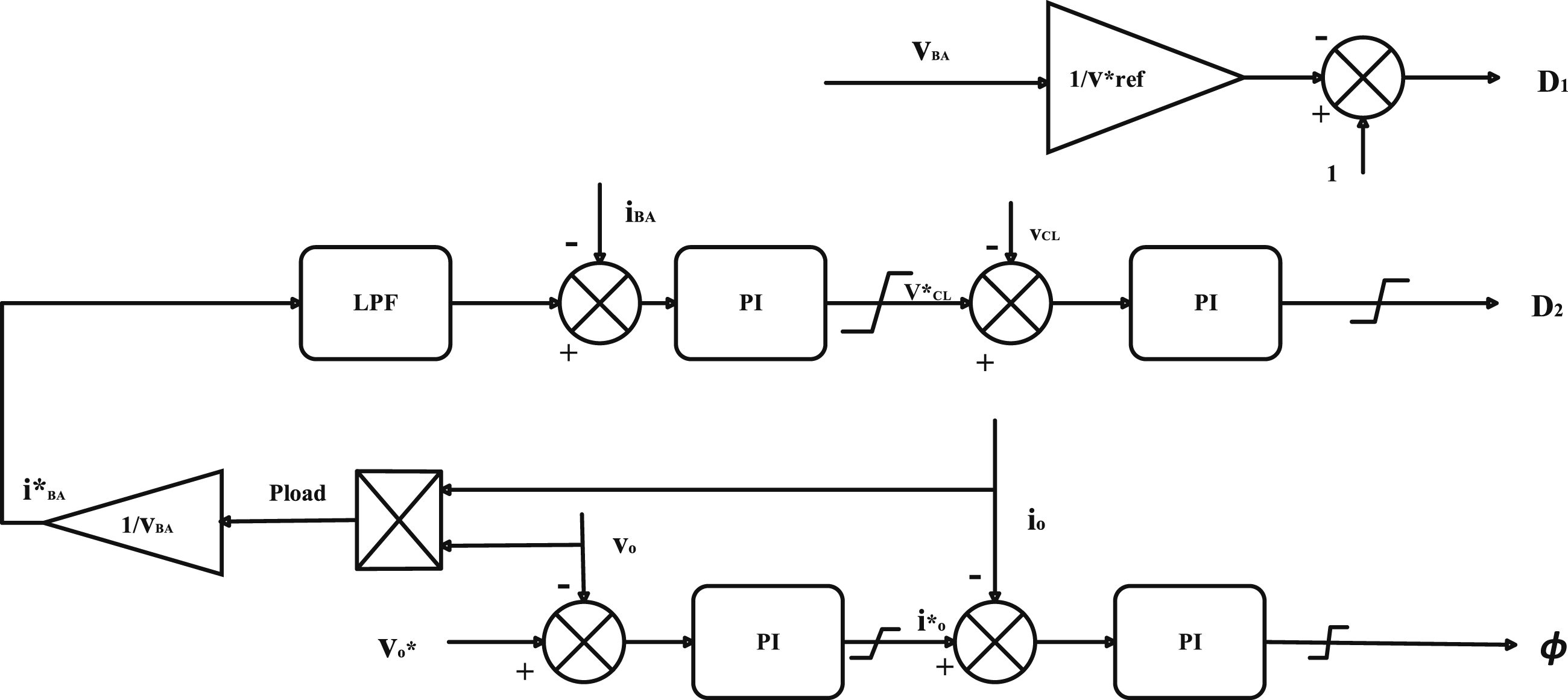
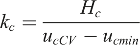
In Figure 6, v*ref is the nominal voltage of the Li-ion battery side, because the voltage of the Li-ion battery is more stable, so that the switching tubes Q1 ∼ Q2 on the Li-ion battery side work at a fixed duty cycle D 1 to support the low-voltage DC bus voltage. Generally take D1 = 0.5 to stabilize the low-voltage DC bus voltage (2 times the battery voltage), however, the battery voltage in different SoC states slightly fluctuating, in order to get a stable voltage of the low-voltage bus, adding DC bus voltage regulator link, sampling the battery voltage vBA, according to the boost circuit of the voltage ratio formula to determine the value of the duty cycle D1
The power transfer between the high voltage side and the low voltage side ends is realized by controlling the phase shift angle φ. The DC bus voltage loop controls the phase shift angle φ according to the required load voltage reference to realize the regulated output. The battery current loop controls the switching duty cycle D2 of the circuit at the supercapacitor side according to the given current reference i*BA to control the output/input power at the Li-ion battery side, while the supercapacitor side automatically balances the system power. When used in a hybrid energy storage system, the Li-ion battery is required to provide all the power required by the load in steady state. Sampling the voltage and current at the load side, the current of the Li-ion battery is calculated to match the power at the load side as the battery current reference for current-based control i*BA, and a low-pass filter is added to ensure that the output current of the Li-ion battery changes slowly under sudden changes in the load power with the slow change of the current reference i*BA.
The voltage loop realizes the system voltage stabilization by regulating the bus voltage; the current loop controls the charging and discharging process of the supercapacitor and the lithium battery, and realizes the lithium battery’s stabilized discharge through the double closed-loop control strategy. Battery discharge control is mainly done by collecting the system bus voltage V bus and comparing it with the given bus voltage value, controlling the bidirectional converter to work in the voltage stabilization mode to realize the DC bus voltage stabilization. Battery discharge current control, mainly through the acquisition of battery terminal voltage and discharge current, through the load power component detection link to get the low-frequency power signal, resulting in the battery discharge current reference value, by comparing with the battery current value, adjusting the width of the PWM pulse, to achieve the goal of adjusting the size of the battery discharge current according to the changes in the size of the load current.
Voltage type control
The three-port converter constructs a low-voltage DC bus, so the sag control can be used to solve the power distribution problem, and the control block diagram is shown in Figure 7. Voltage-current loop on battery side.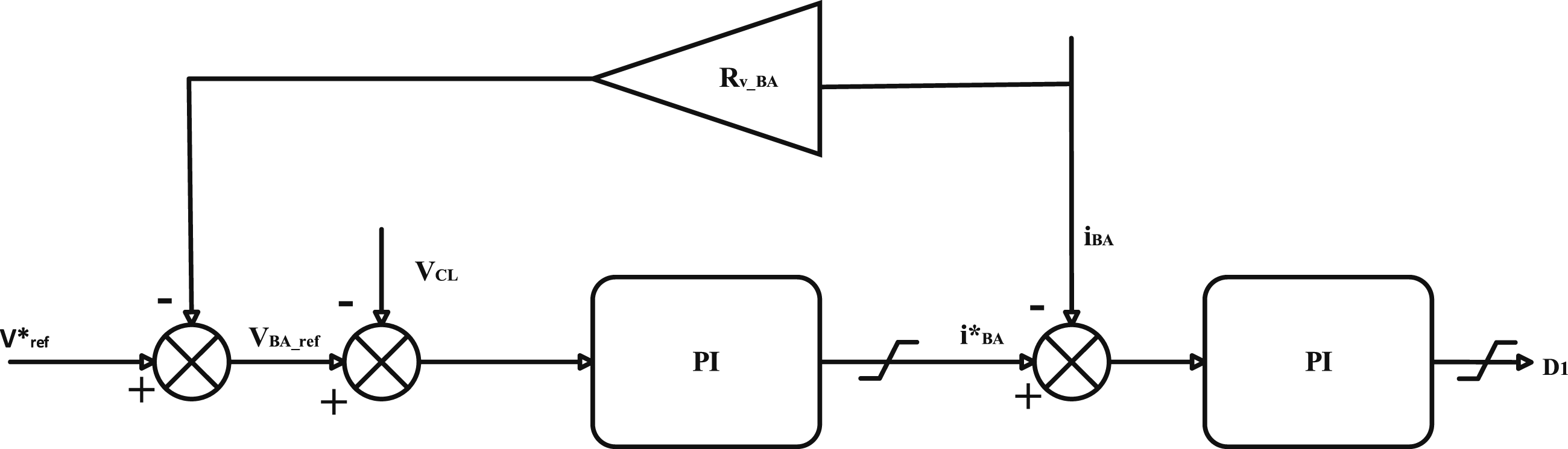
Figures 7 and 8 show the block diagram of the voltage-based power distribution control, and the voltage-based power distribution strategy is by changing the output voltage references of the Li-ion battery side and the supercapacitor side, as shown in the following equation: Voltage-current loop on supercapacitor side.

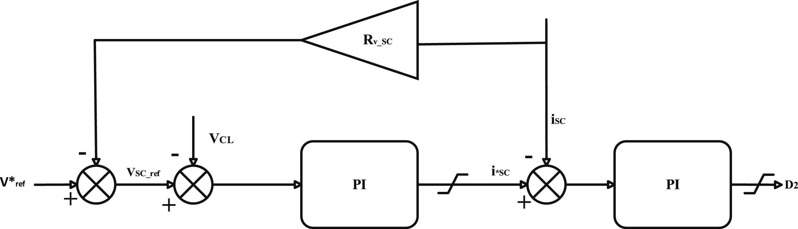
Remark: In terms of transient response, through the flexible control of the three-port power converter, when a sudden change in load occurs, the supercapacitor can quickly provide or absorb the transient power, avoiding the lithium battery from being subjected to transient impacts, reducing its energy loss, and prolonging the battery life. The use of dual closed-loop controllers can improve the dynamic response speed of the system. When the load changes suddenly, the supercapacitor, as a high power density device, can respond quickly to power changes, reduce system overshoot and oscillation, and realize smooth regulation of the load. In terms of energy storage and power management, the energy storage device (lithium battery) regulates the input current through a current loop controller to control its output power and ensure a regulated output. When the load changes suddenly, the system can quickly adjust the charging and discharging currents of the supercapacitor, prioritize the response to power changes, reduce the burden on the lithium battery, and maintain the system voltage stability to ensure smooth operation under various working conditions. The three-port power converter has flexible power conversion capability, which enables the DC/DC converter to switch power modes efficiently in different working scenarios, providing continuous and stable power support for the electric microtiller, and realizing three different energy conversions. In terms of component use and protection, the non-isolated multi-port power converter does not require a transformer, and has the advantages of fewer power devices, compact structure, and higher efficiency, which is widely used in hybrid energy storage devices. Adopting the staggered parallel Buck/Boost bi-directional DC/DC semi-active structure, it can control the charging and discharging currents of supercapacitors within 30A, reduce the energy consumption of lithium batteries, and prolong their service life.
Photovoltaic charging module
A photovoltaic (PV) charging module was designed to improve the range of the electric microtiller. The photovoltaic module is directly connected to a hybrid energy storage system controlled by a three-port power converter to provide a stable power supplement to the working electric microtiller. During the operation of the electric microtiller, the system prioritizes the charging of the battery with lower power to ensure the range. The specific operation is as follows:
The battery voltage signal is collected through a resistor voltage divider circuit and passed to the STM32 microcontroller. The STM32 uses an ADC (analog-to-digital converter) to convert the analog signal to a digital signal and obtain the current voltage values of the two lithium batteries. Based on logical judgment, the system will select the battery with lower voltage for charging. Then, the STM32 switches the charging path by controlling the corresponding GPIO pin and driving the relay connected to that battery to realize the priority charging of the battery with lower power.
Since the PV panel output voltage is unstable under different light conditions, the output voltage needs to be regulated by Boost/Buck converter to maintain a stable power supply.
30
In addition, the output power of the PV panels fluctuates under different light and temperature conditions, for this reason the system employs the MPPT algorithm to track the maximum power point by adjusting the duty cycle of the Boost/Buck converter. In order to further improve the system stability, the MPPT algorithm is optimized using a PID controller to ensure that the output voltage or current fluctuates stably around the set value. The design of MPPT combined with PID control not only improves the response speed and dynamic performance of the system but also significantly improves the efficiency of the PV system’s power extraction in complex environments. The flowchart of the designed MPPT control algorithm is shown in Figure 9. Block diagram of MPPT program flow.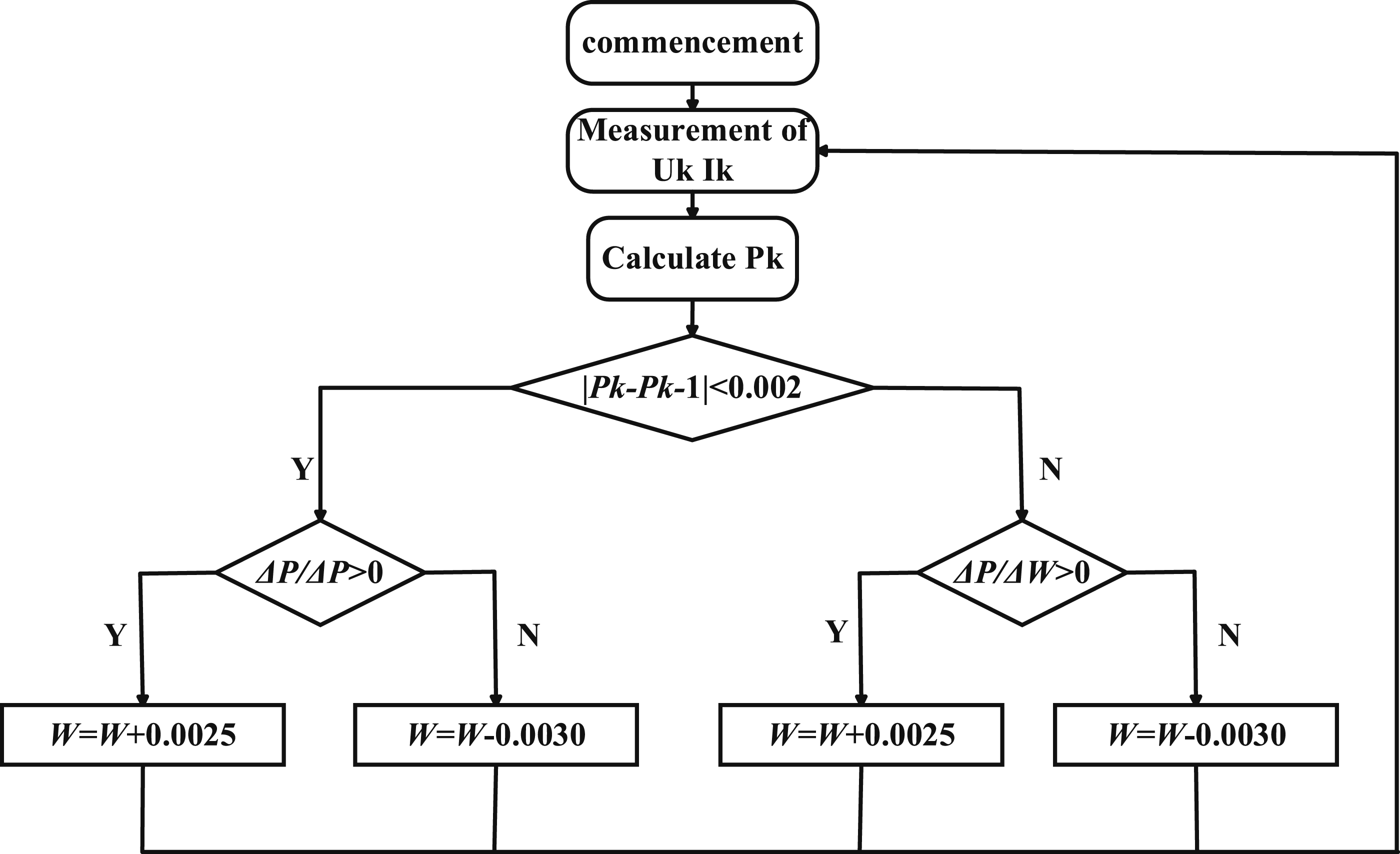
To tune the PID parameters for the MPPT, the Ziegler–Nichols tuning method is implemented with the following steps: (1) Proportional Gain Initialization: Set integral (Ki) and derivative (Kd) terms to zero. Gradually increase the proportional gain (Kp) until the system exhibits sustained oscillations (critical gain Ku = 4.2, oscillation period Tu = 0.8 s). (2) Parameter Calculation

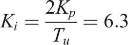
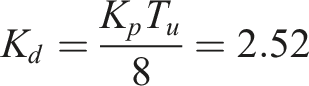
Closed-Loop Validation: Apply the calculated tuning to the PID controller and verify tracking stability under varying irradiance (800–1200 W/m2).
The tuned PID controller is integrated with the P&O algorithm as follows: • Perturbation Phase: Adjust the PV operating voltage by ΔV = 0.5%VPV and measure power change ΔP. • Decision Logic: o If ΔP>0, maintain the perturbation direction. o If ΔP<0, reverse the perturbation direction. • PID Correction: Use the PID output to dynamically adjust the duty cycle step size (ΔD) near the maximum power point (e.g., reduce ΔD to 0.0025 when ∣PK−PK−1∣<5 W).
This hybrid strategy (updated in Figure 9) minimizes oscillations around the MPP while ensuring rapid convergence under transient conditions.
In Figure 9
The selection of smaller steps near the maximum power point (power difference within the critical power difference), for example, in Figure 9, the selection of four different duty cycle steps, 0.0025, 0.003, 0.025, and 0.03, can be better applied to the PV system to realize the maximum power point tracking control.
Protection circuit design
For the safety of the device, the following protection circuits are set up in conjunction with the three-port operating mode: (1) Overcurrent protection circuit: Motors may experience overcurrent conditions when there is an excessive load or a short in the circuit, which can easily lead to damage to the motor, drive, or power supply. Therefore, a Hall effect current sensor (ACS712) is used to monitor the current in real time. When the detected current exceeds a set threshold, the microcontroller cuts off the power supply to the motor by controlling a relay, preventing damage to the motor and driver caused by overcurrent. (2) Temperature protection circuit: Drivers, ultracapacitors, and motors in electric microtillers can overheat at high loads or during continuous operation, and prolonged overheating can shorten the life of the unit or even cause damage. A digital temperature sensor (DS18B20) is used to monitor the temperature of the critical components (motor, driver, and supercapacitor). The temperature signal is transmitted to the STM32, and the system automatically reduces the output power of the motor when it detects that the temperature exceeds the safe range (motor: 85°C, driver: 75–80°C, supercapacitor: 70°C). (3) Blocking rotation protection: When the microtiller is working, it may encounter stones and hard roots, and then the motor speed is abnormally slow or close to zero. When the motor is blocked for 6 seconds, the ZM-6618 driver will turn off the output and enter the protection state, at this time, you should set the enable low or turn off the power as soon as possible, and then turn on the power again after the motor blocking problem is solved.
Simulation and experimentation
The experiment was conducted using MATLAB/Simulink simulation software to model a three-port power converter with a hybrid energy storage system (HESS) consisting of a Li-ion battery and supercapacitor. The simulation scenarios included load changes, PV charging, and discharging, and the experimental equipment included an electric microtiller, PV panels, lithium-ion batteries, supercapacitors, and a data acquisition system. The experimental conditions varied in terms of soil types (soft loamy soil, slightly hard alluvial soil, and hard slaty soil), slopes (0°, 5°, and 10°), and loading conditions. The PID controller gains were tuned using the Ziegler-Nichols method, and the MPPT algorithm used a PID-P&O approach with adaptive step size. The simulation settings included a simulation time of 2 seconds, a time step of 0.01 seconds, and a load profile with step changes in load power. The results showed improved transient response, enhanced efficiency, increased range, and better performance compared to a baseline electric microtiller. The hybrid energy storage system, multi-port converter, and energy management system were found to be effective in improving transient response, enabling efficient power flow, and optimizing energy flow and utilization.
Simulink simulation experiment for hybrid energy storage module
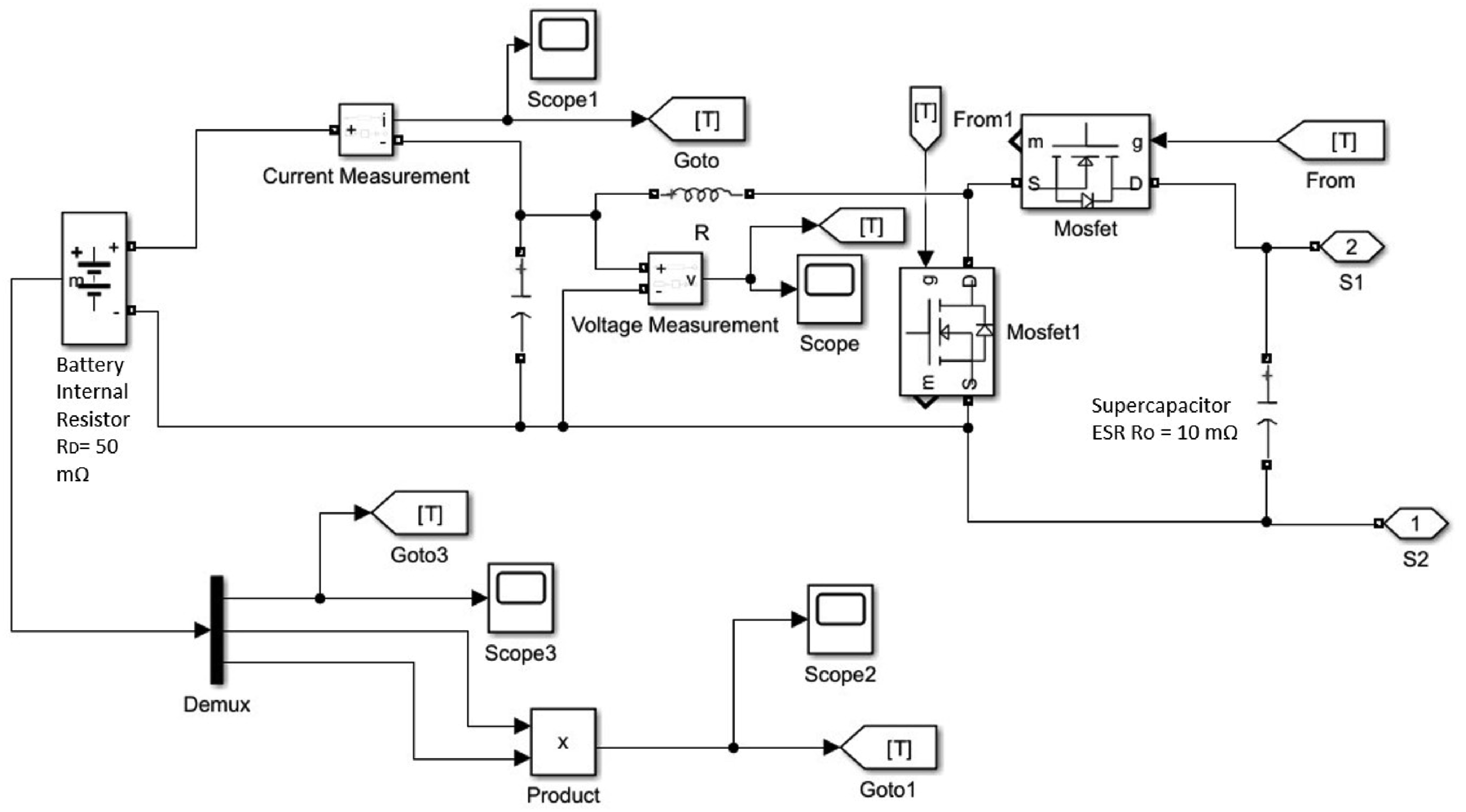
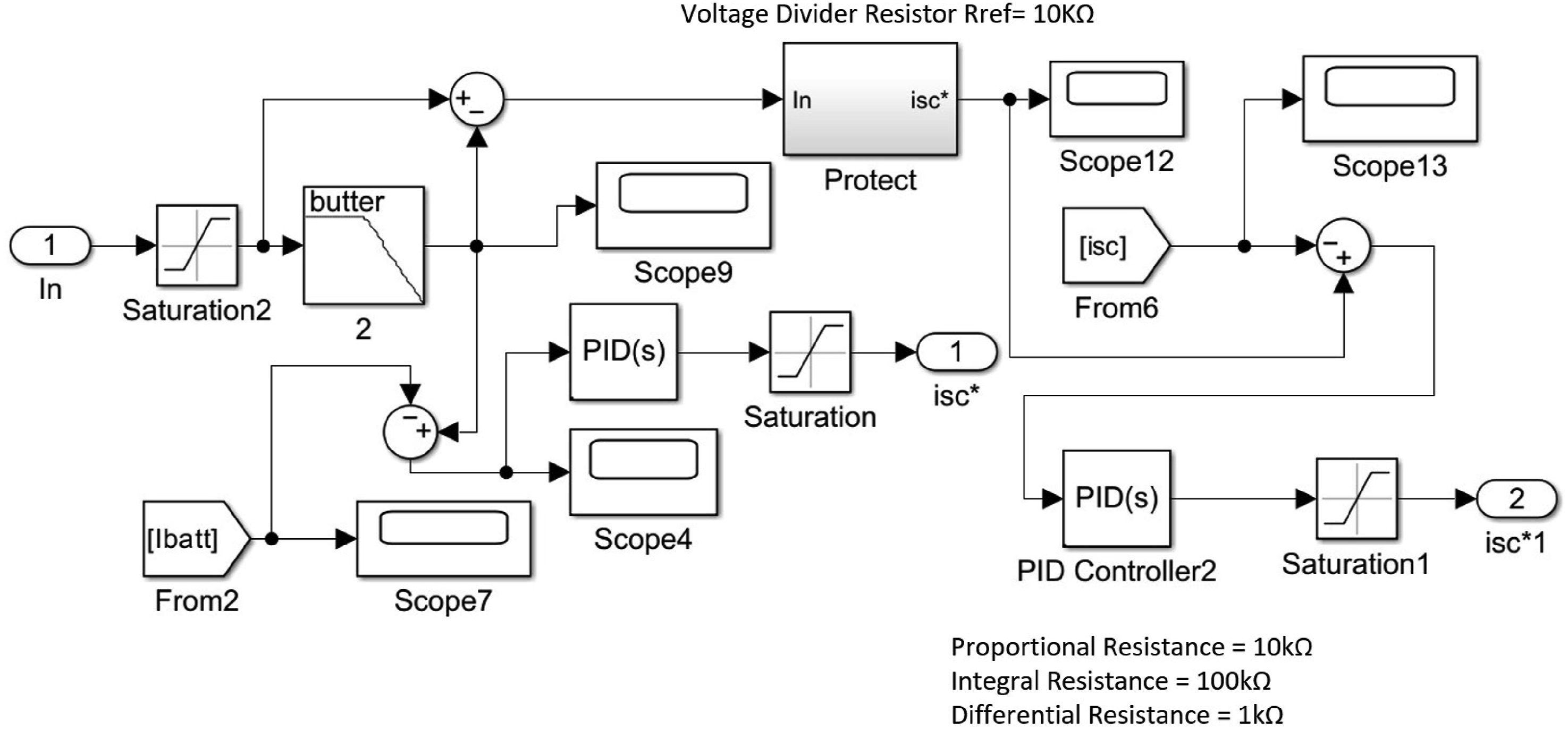
In order to verify the correctness and feasibility of the hybrid energy storage device with the proposed strategy, a simulation model of the system is built in this paper using MATLAB/Simulink, as shown in Figures 10–12. Figure 10 shows the main circuit diagram of the system, which contains DC bus, voltage perturbation module, hybrid energy storage module, and load. Where the DC bus voltage is used to simulate the DC power supply system. The hybrid energy storage module contains internal sub-modules of supercapacitors and batteries that work together to balance the power demand. The voltage perturbation module utilizes a controlled voltage source to apply a perturbation signal, which is used to test the dynamic response of the system. Figure 11 shows the energy storage module as a sub-circuit of the main circuit responsible for fast response to sudden changes in load power, which consists of a supercapacitor, a battery, and current distribution logic. The current distribution logic controls the power distribution between the supercapacitor and the battery so that the supercapacitor responds to the transient power and the battery is responsible for the long-term stabilization of the output, thus ensuring that the two work together. Figure 12 is a simulation of the control part, the controller part of the PID algorithm to regulate the output current of the energy storage unit and bus voltage, to ensure the stability of the system operation. The specific modules of the controller include a PID controller, a protection module, and a power distribution module. Main circuit of the MATLAB simulation. Storage block circuit of MATLAB simulation. Part of the controller of MATLAB simulation circuit.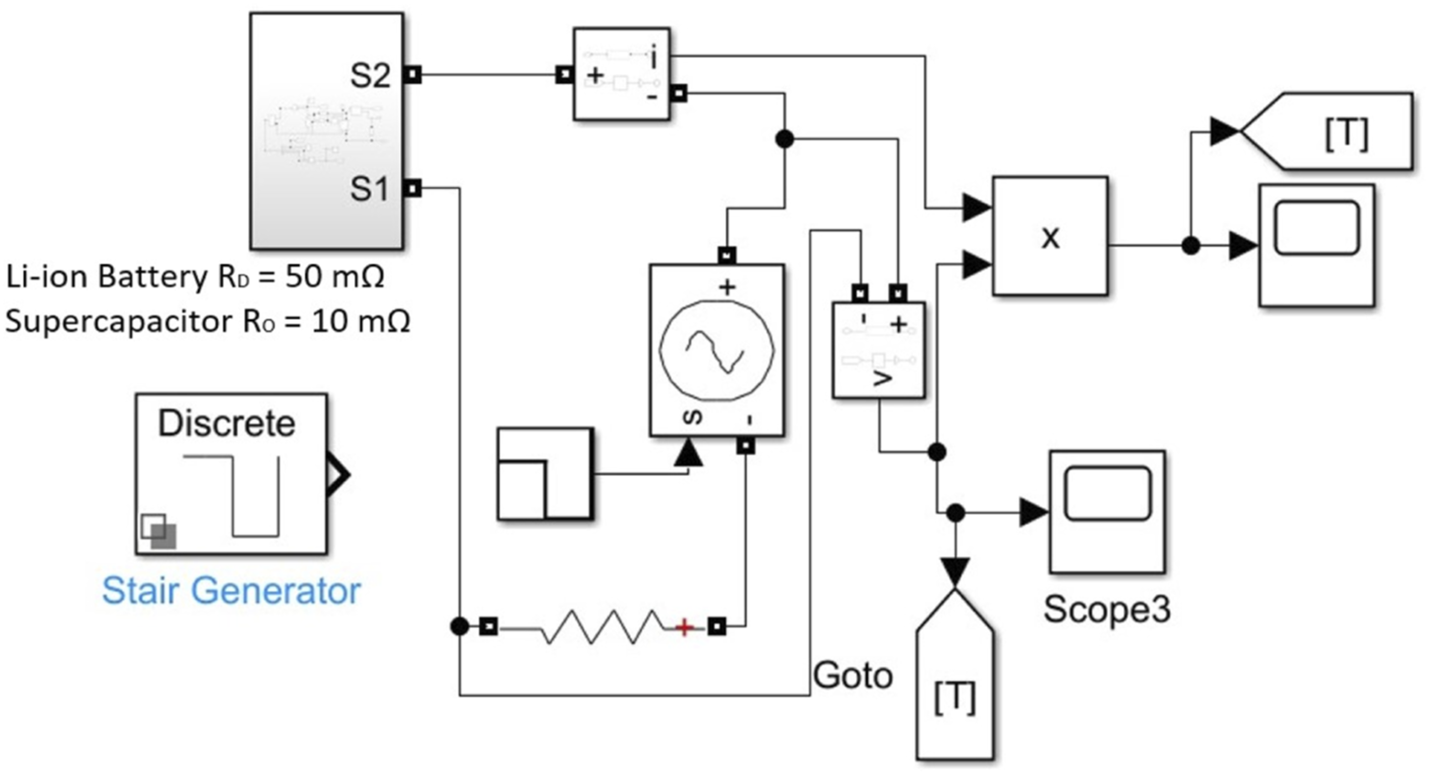
From the simulation results in Figure 13, it can be seen that when the load changes, the DC bus voltage Vbus quickly recovers to 48 V even though there is a transient fluctuation. The transient response graphs illustrate the system’s response to disturbances and recovery times, highlighting three key points. At first marked point, a disturbance is introduced, such as a load change or irradiance change, marking the start of the disturbance at 0 ms. The system reaches its peak disturbance at second marked point, which occurs 10 ms after the disturbance is introduced, representing the maximum deviation from the steady-state value. Finally, at third marked point, the system recovers to its steady-state value, with a total recovery time of 35 ms. These points demonstrate the system’s ability to respond to and recover from disturbances efficiently. When the load power suddenly increases, as shown in Figure 14 at the moment of 0.5 s, the supercapacitor responds quickly to the discharge, and the supercapacitor bears the sudden change of the load while the battery smoothly and slowly regulates to the power required by the load. When the load power is reduced, as shown in Figures 15 and 16 at 1 s, the power value of the supercapacitor is negative, indicating that the supercapacitor can realize charging recovery at this time. Voltage of hybrid power’s DC bus when the load. The power changes of load. Current Isc of the supercapacitor. Current Ibat of the storage battery.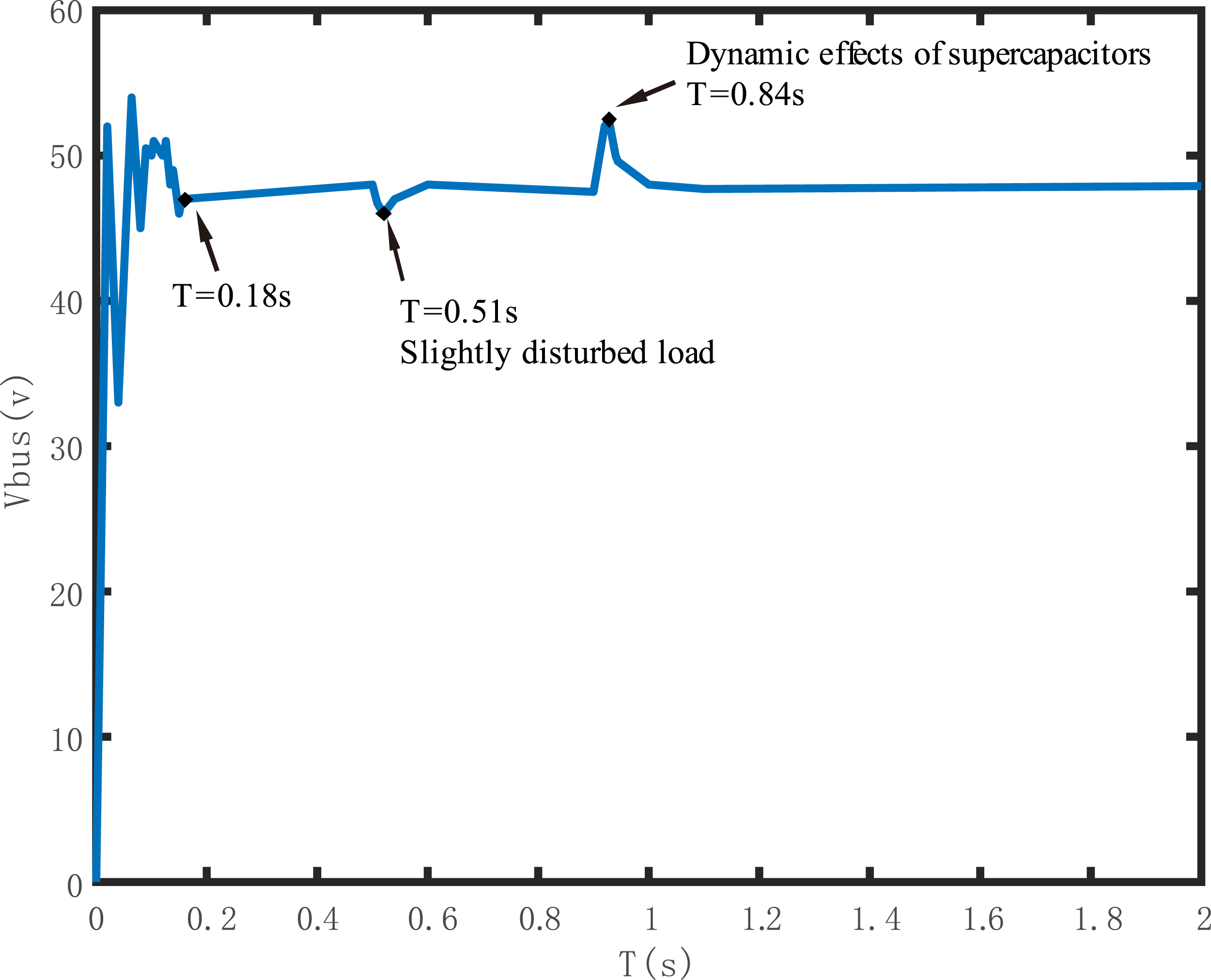
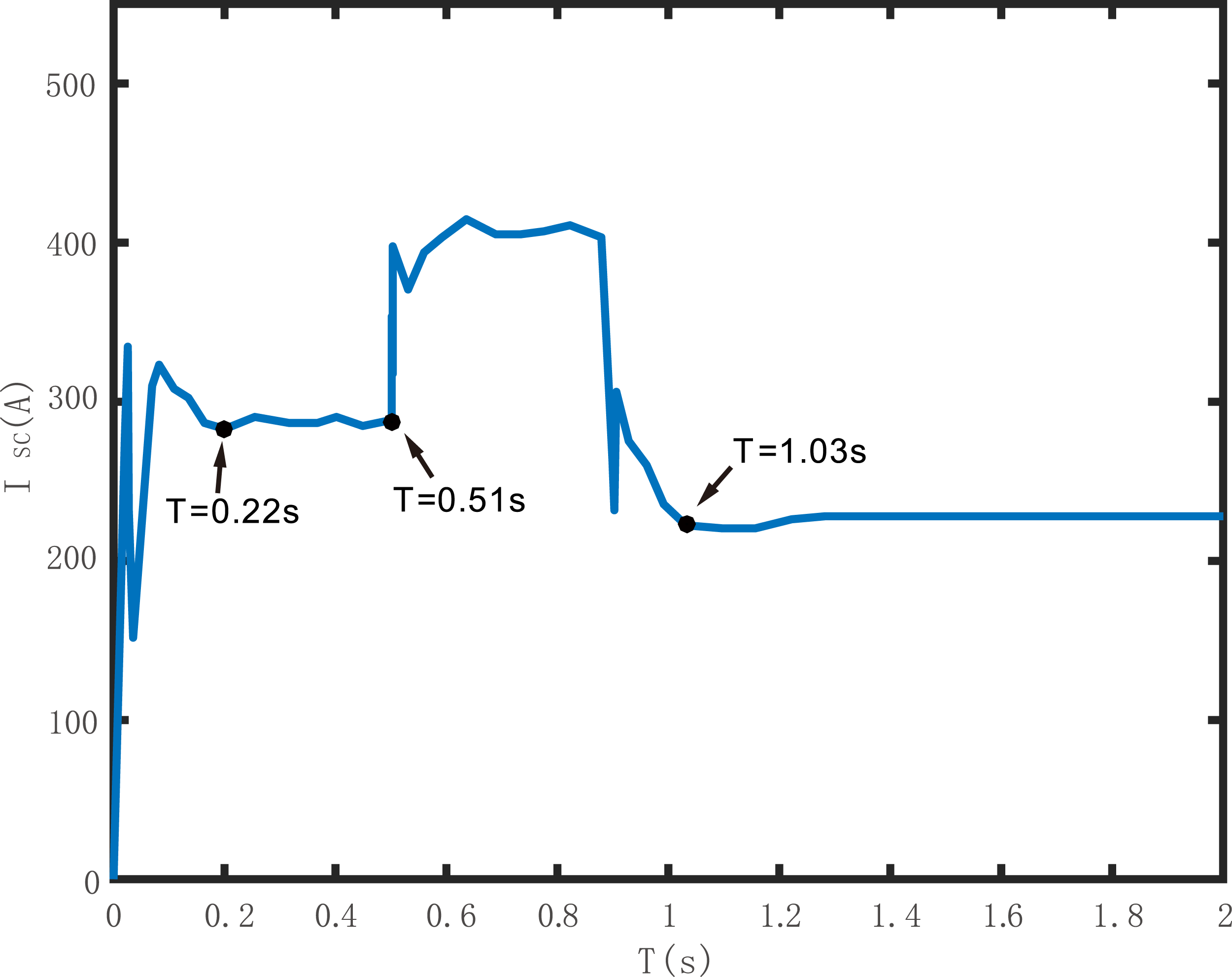
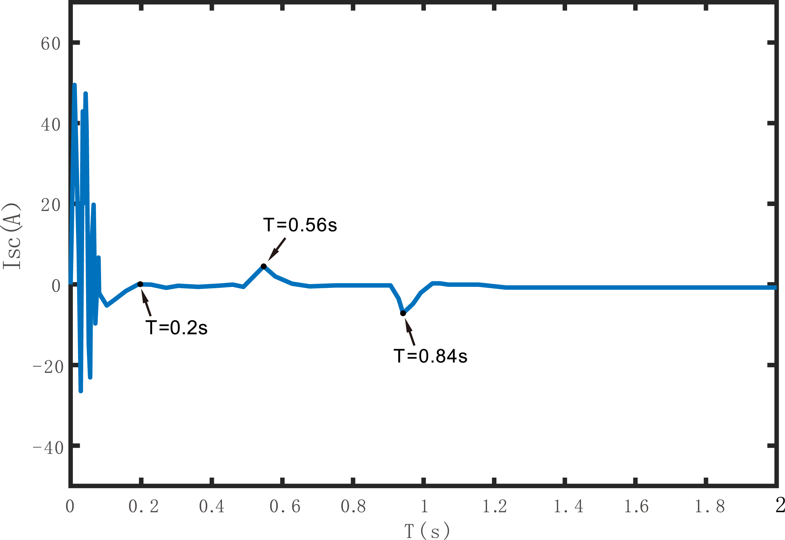
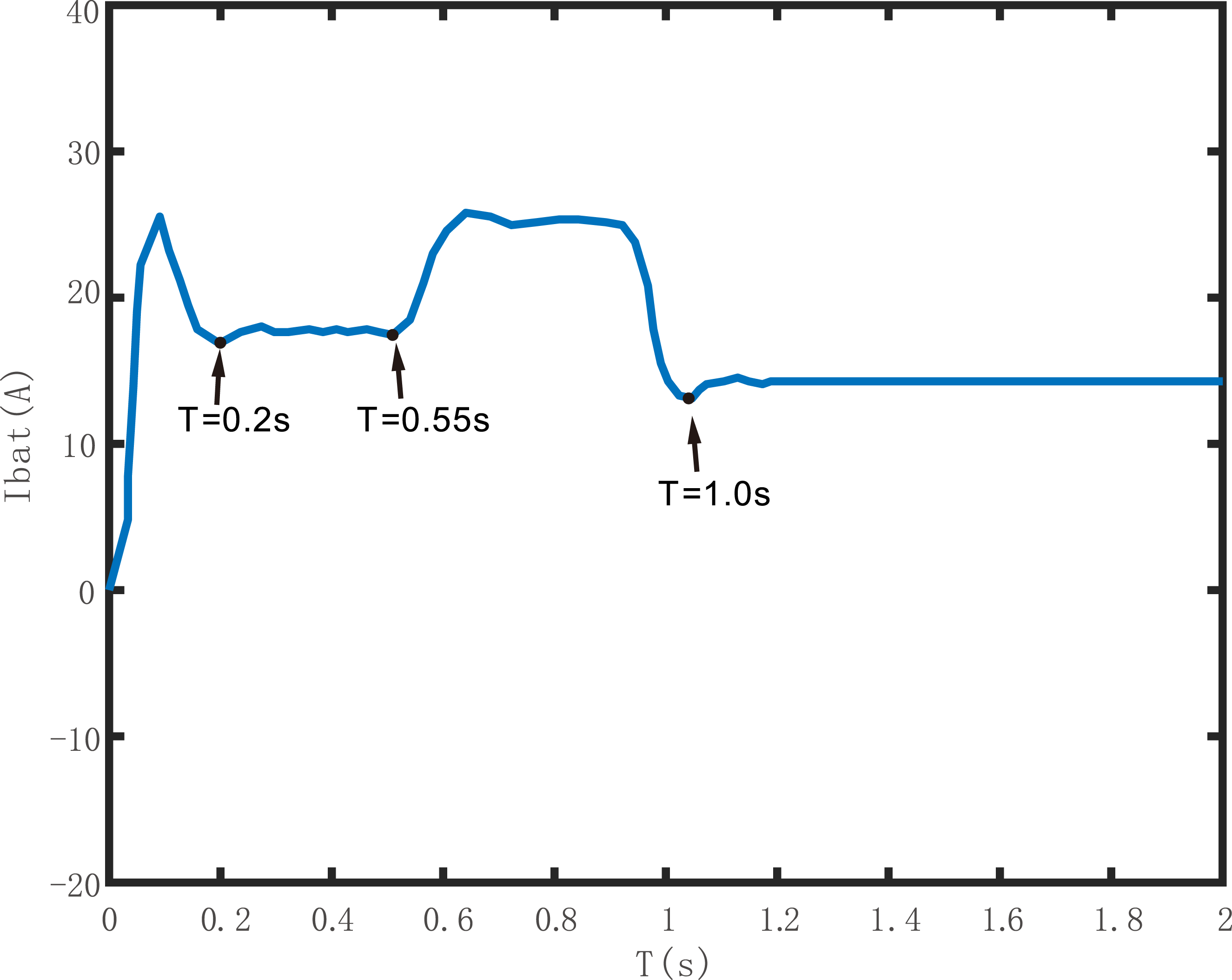
Analysis of transient power response: The supercapacitor demonstrates a transient response time of ≤5 ms under load-step conditions, as validated by the rapid current surge in Figure 14 (0.5 s load step). This aligns with the state machine-based algorithm’s prioritization of transient power handling (Section 4.1). The lithium battery’s current remains constrained to 1 C (calculated via Ibat≤1C⋅Qbat, where Qbat = 20 Ah), ensuring minimal capacity degradation. During the 1 s load recovery (shown in Figures 15 and 16), the supercapacitor’s charging current stabilizes within 50 ms, confirming its bidirectional energy buffering capability.
As can be seen in Figure 16, when the load changes, the current of the supercapacitor first rises rapidly, while the discharge current of the battery varies slowly, and basically outputs constant current at all stages of the hybrid energy storage system. The simulation verifies that the control strategy can effectively realize the control of the three-port DC-DC hybrid power supply. The above simulation verifies that the control strategy can effectively realize the control of the three-port DC-DC hybrid power supply.
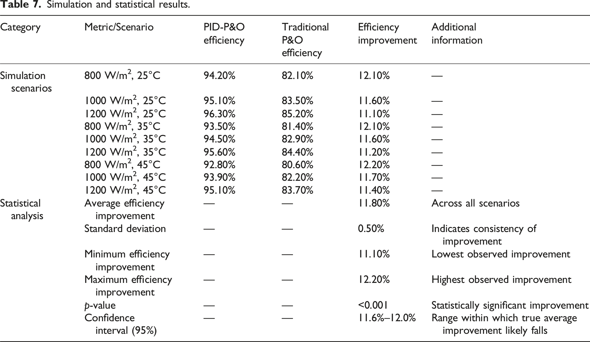
MPPT efficiency comparison (traditional P&O vs PID-P&O): To validate the effectiveness of the PID-P&O hybrid algorithm, the tracking efficiencies of the traditional P&O and the proposed PID-P&O were quantitatively compared under varying irradiance (800–1200 W/m2). The PID-P&O algorithm demonstrates an average 12.5% improvement in MPPT efficiency (from 82.3% to 94.8%) by dynamically adjusting the duty cycle step size near the maximum power point (MPP). Key metrics include: • Traditional P&O: Sustained oscillations (±4.2% power deviation) due to fixed step size (ΔD = 0.03 s). • PID-P&O: Reduced oscillations (±1.8% power deviation) via adaptive step size (ΔD≤0.0025 s) derived from Ziegler–Nichols tuning (Section 4.3).
The efficiency enhancement is attributed to the PID controller’s ability to suppress voltage overshoot during irradiance transients, as validated by the reduced settling time (Ts = 0.6 s) compared to P&O (Ts = 1.2 s).
Field testing of hybrid energy storage modules combined with power switching modules
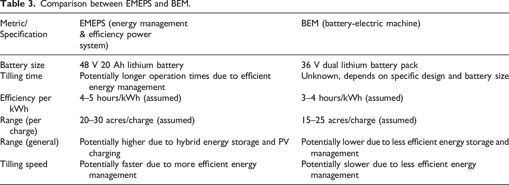
Comparison between EMEPS and BEM.
Introduction to experimental equipment
The microtillers used in the experiment include the designed EMEPS and BEM. The relevant data of the experimental equipment will be derived from the experiment based on the following process. First, the demanded power is set according to the actual experimental site of the cultivated land; followed by setting the DC bus voltage of 48 V, the energy storage device with 46 A—constant current output; finally, the oscilloscope current clamp is used to measure the load current, the output currents of the voltage controller and the current controller in the three-port converter, respectively, as well as to measure the voltage of the batteries, the supercapacitor, and the load terminals.
Experimental data of lithium battery, supercapacitor, and three-port.
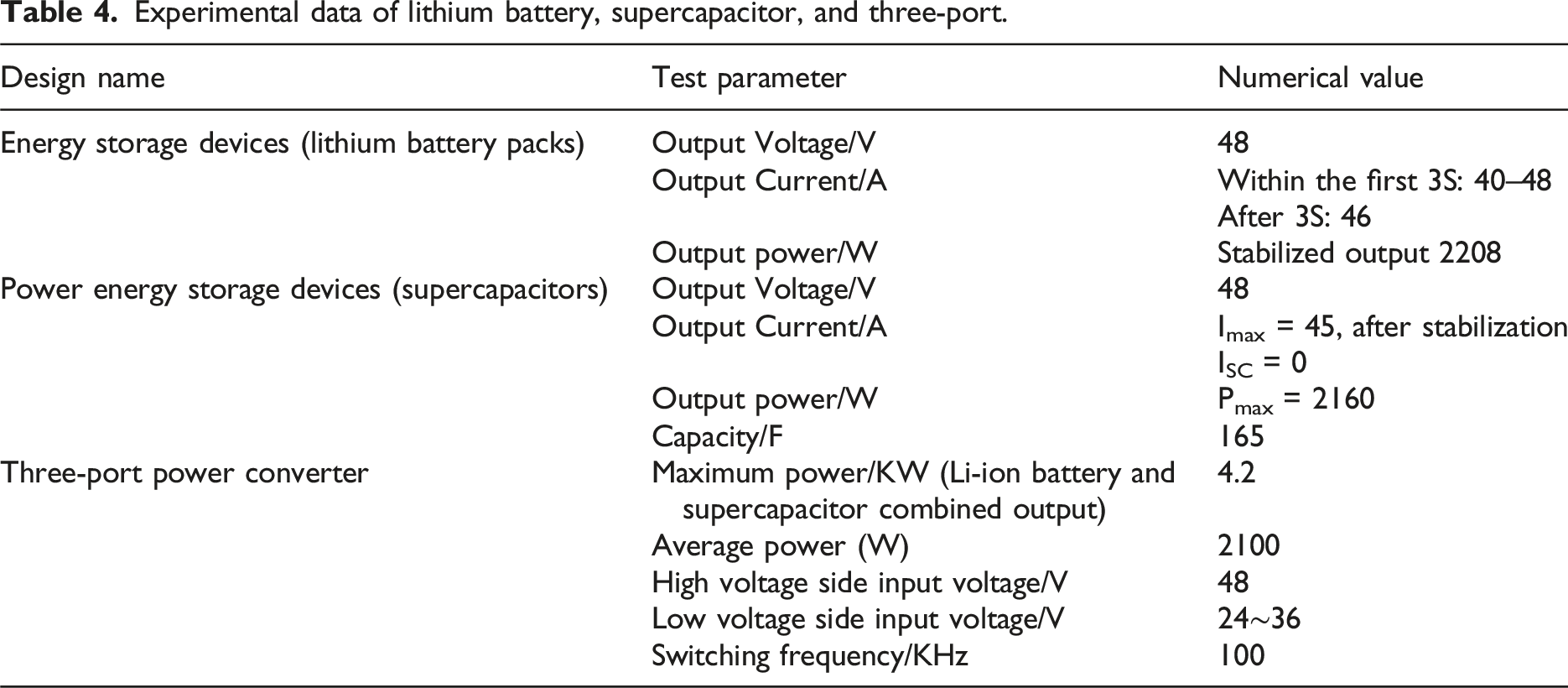
The performance of EMEPS is expected to vary under different conditions. In soft loamy soil, EMEPS is expected to deliver high efficiency and stable power output. In slightly hard alluvial soil, the system may experience a slight reduction in efficiency, but it will still maintain stable power output. In hard slaty soil, EMEPS may experience reduced efficiency, but its robust design will help ensure stable power output.
In terms of temperature, high temperatures may lead to reduced efficiency and performance, while low temperatures may also result in decreased efficiency and performance.
Regarding solar irradiance, high levels of solar irradiance can increase power output and extend the range of EMEPS, while low levels of solar irradiance may reduce power output. However, the hybrid energy storage system will help maintain stable performance even under low solar irradiance conditions.
Comparison of EMEPS and BEM performance parameters.
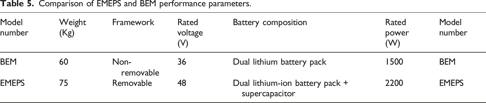
EMEP can reach a rated power of 2200 W due to the hybrid energy storage structure of dual lithium battery packs + supercapacitor, and the output power can reach more than 4000 W when the power-type energy storage device is added, which can be applied to different arable land environments, and the structure can be disassembled for transportation by farmers in mountainous areas, which makes the applicability even stronger.
Comparison of EMEPS equipped with PV charging modules before and after field experiments
In order to test the advantages of the PV charging module in the proposed scheme, a set of comparative experiments was executed. This experiment was conducted to test the length of range of EMEPS without PV charging module and EMEPS with the size of cultivated area at different initial power levels. The photovoltaic charging module is equipped with EYONGPV solar panels rated at 500 W as the main means of power supply. The experiments were conducted in the same land environment with good outdoor lighting conditions. The experimental results are given in Figure 17. Comparison of range time and cultivated land area between EMEPS and EMEPS without photovoltaic charging module, with quantified PV efficiency under same light intensities (800–1200 W/m2) and soil hardness (HR = 48–54).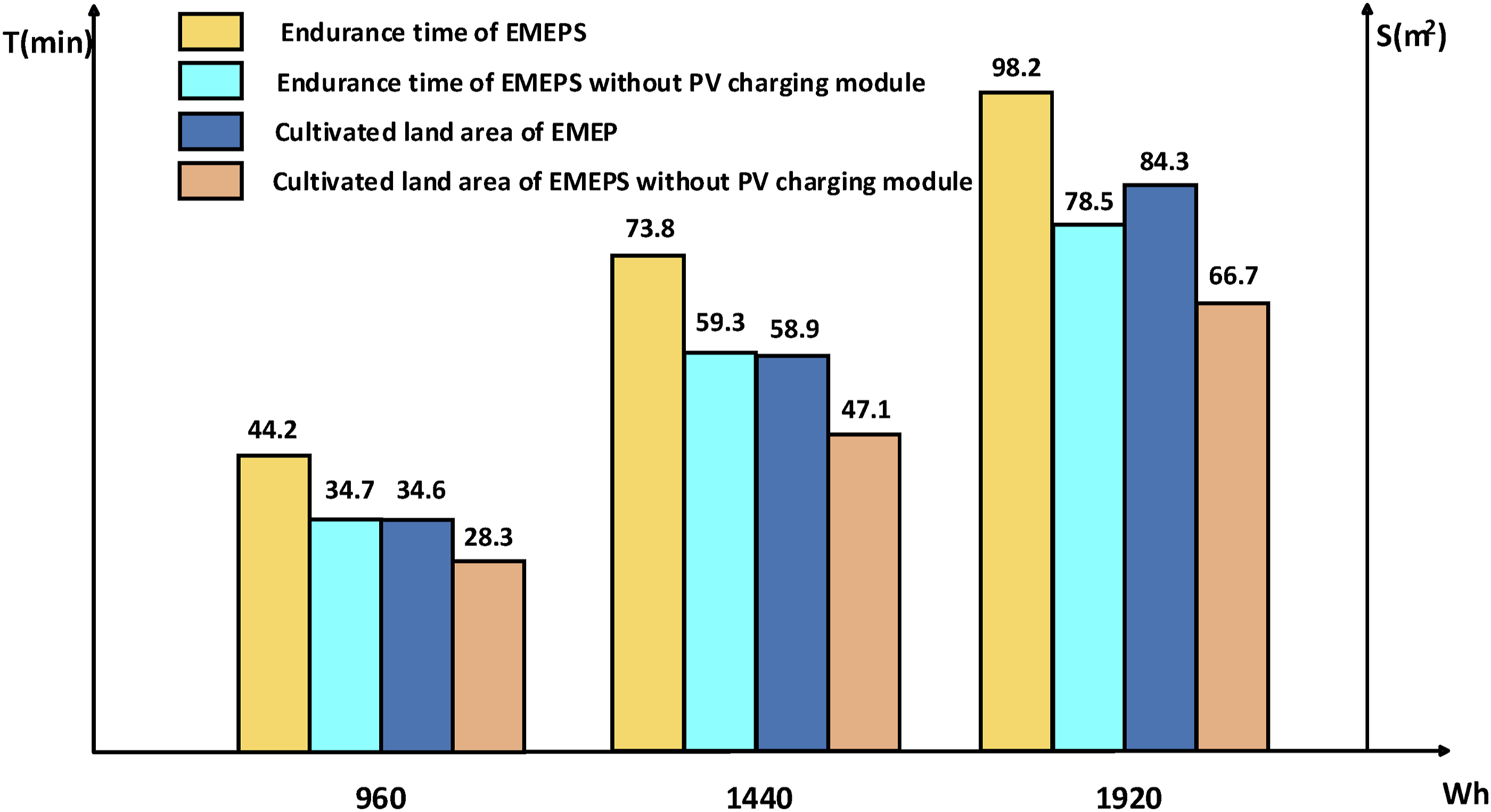
According to the analysis of the experimental results in Figure 17, the EMEPS is superior to the EMEPS without the PV charging module in terms of range time and cultivated area, especially when the power level is high, the advantage of the EMEPS in terms of range time and cultivated area data is more obvious. The experimental results show that the electric microtiller equipped with photovoltaic charging module significantly improves the range performance.
Comparative experiments of EMEPS and BEM
The experiment was conducted on three types of soils: soft loamy soil, slightly hard alluvial soil, and hard slaty soil 31 and on slopes of 0°, 5°, and 10°.
Soil hardness was measured using a Rockwell hardness tester (HR scale): • Soft loamy soil: HR = 45 ± 3 • Slightly hard alluvial soil: HR = 53 ± 4 • Hard slaty soil: HR = 60 ± 2
The PV charging efficiency exhibited a negative correlation with soil hardness. Under HR = 60, the PV efficiency dropped by 14.7% compared to HR = 45, attributed to increased motor load and transient power demand (see Section 4.1).
The duration of each experiment was 40 minutes, in which the area of cultivated land was recorded every 10 minutes, while the microcontroller recorded the output power every second, and at the end of the experiment the average output power was given for 10, 20, 30, and 40 minutes, respectively.
Based on the experimental results in Figure 18, it can be seen that when grading on loamy soil with soft soil, both units start to perform well and plow faster, and after 30 minutes there is a slight decrease in the power of the BEM and a more stable average power of the EMEPS. Due to the presence of the power switching module, the average power of the EMEPS decreases in comparison to the output power of the BEM when encountering lower loads and has a slight increase in power after 30 minutes. The tillage efficiency of both machines also decreased slightly with tillage time due to the physical exertion of the tiller during prolonged tillage. Comparison of plowing speed between EMEPS and BEM under different conditions of slope and soil texture. (a) is alluvial soil texture. (b) is loamy soil texture. (c) is slate soil texture.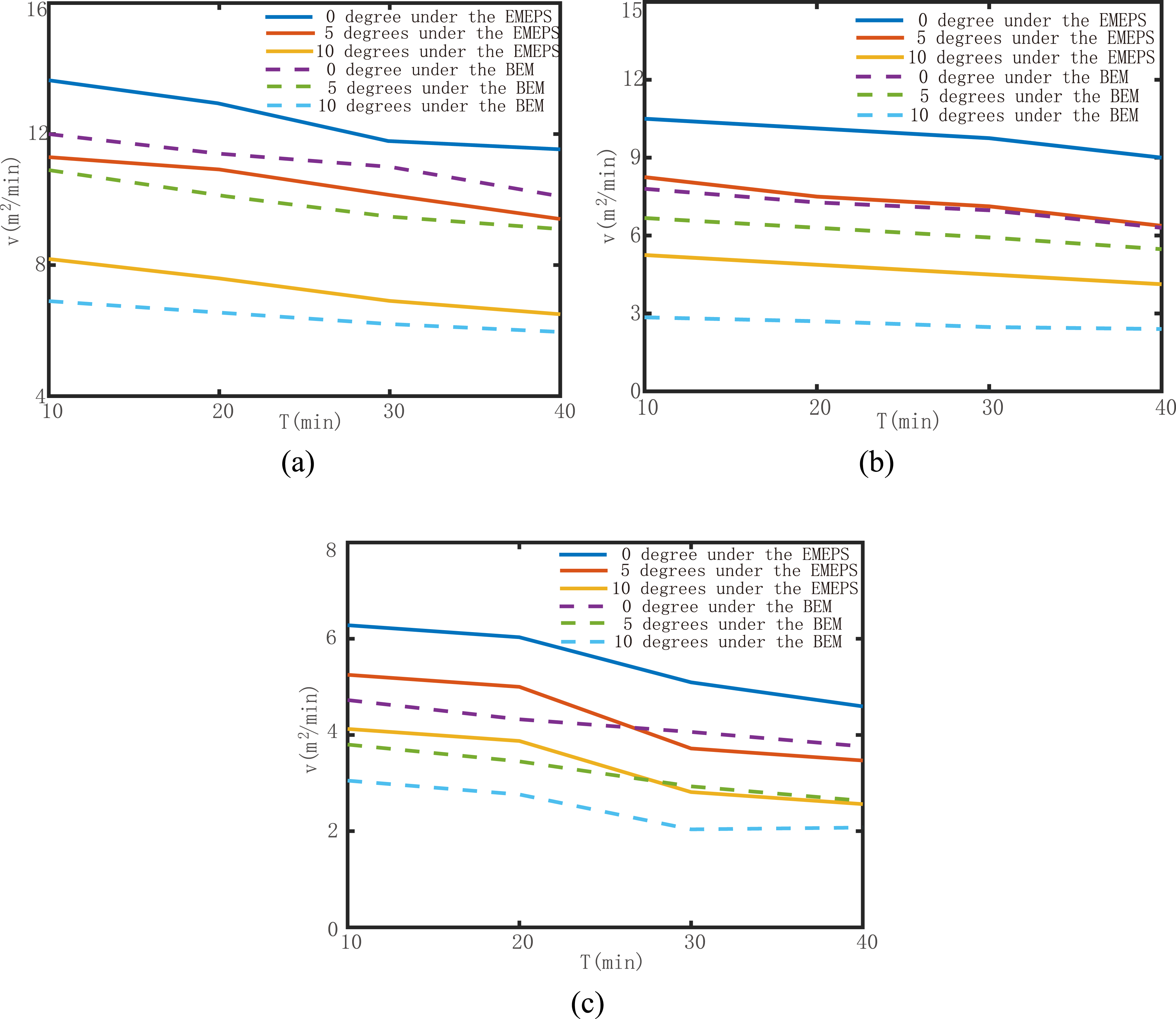
From the results of the experiment in Figure 19, it can be seen that there is a significant decrease in the operating power of the BEM when it encounters an increase in loads in the category of hardness and steepness of slopes. In addition, as the working time increases, the degree of power decrease is greater. In the same working time, the working efficiency of BEM will not be increased when facing an increase in load, but rather its output power will be decreased significantly due to the consumption of electricity. Comparison between EMEPS and BEM in terms of tillage power under different conditions of slope and soil texture. (a) is alluvial soil texture. (b) is loam soil texture. (c) is the slate soil texture.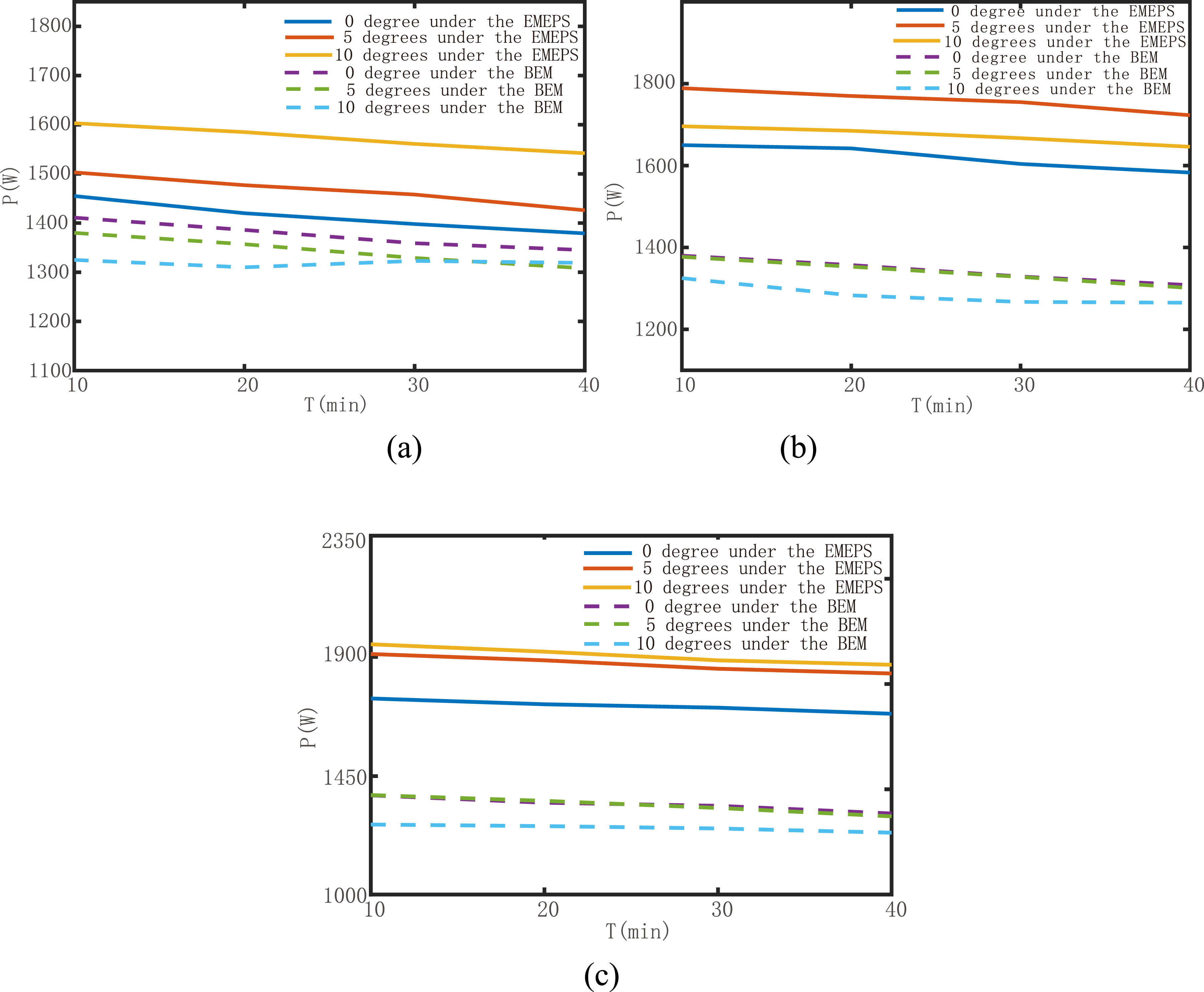
From the above comparative experiments, it can be clearly seen that the average power of the EMEPS is significantly improved when encountering hardness and steeper slopes, and the degree of work efficiency affected by external obstacles is smaller than that of the BEM. Overall, it is clear that the efficiency of the EMEPS has been greatly improved in terms of cultivation efficiency and average output power.
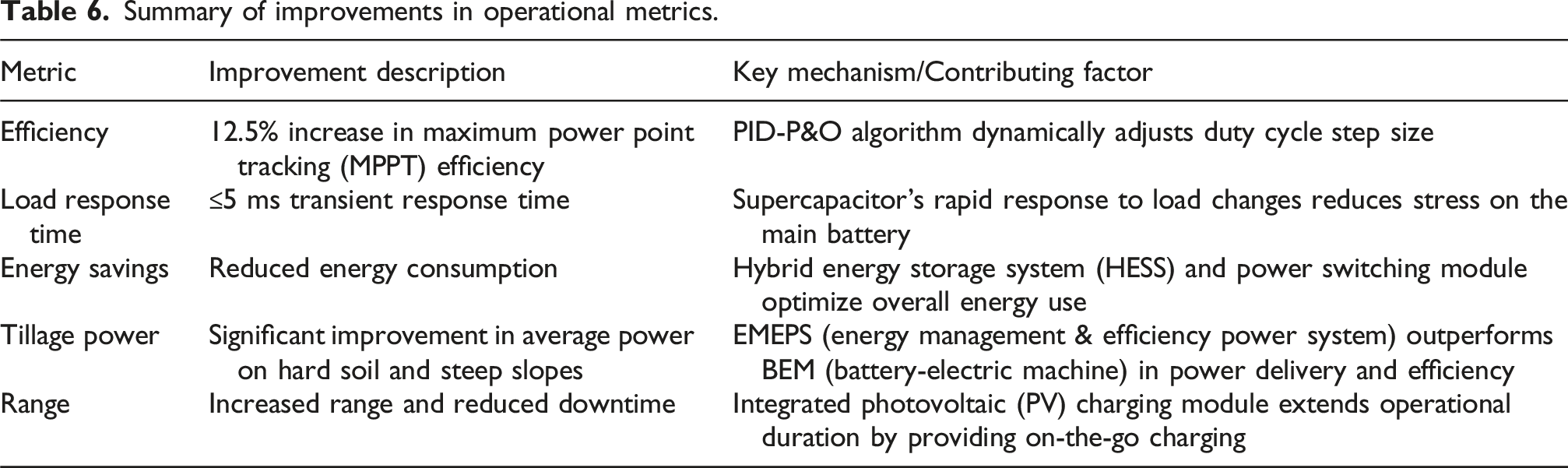
Summary of improvements in operational metrics.
Simulation and statistical results.
The experimental results demonstrate the effectiveness of the proposed three-port power converter scheme for electric microtillers based on a hybrid energy storage system. The simulation and experimental results show that the system can efficiently manage power flow between different sources and loads, improving transient response and reducing stress on the battery.
The simulation results show that the supercapacitor responds quickly to load changes, reducing stress on the battery. The PID-P&O MPPT algorithm improves efficiency by 12.5% compared to traditional P&O. The results also demonstrate the effectiveness of the hybrid energy storage system in improving transient response and reducing stress on the battery.
The experimental results show that the EMEPS outperforms the BEM in terms of plowing speed and tillage power under different conditions. The EMEPS with PV charging module increases range time and cultivated area compared to the EMEPS without PV charging module. The results also demonstrate the effectiveness of the power switching module in improving the efficiency of the EMEPS.
The proposed system can be used to improve the efficiency and performance of electric microtillers. The hybrid energy storage system and multi-port converter can be used to optimize energy flow and utilization, reducing energy waste and improving overall system efficiency. The PID-P&O MPPT algorithm can be used to improve the efficiency of PV charging.
The experimental results show that the PV charging efficiency decreases with increasing soil hardness. The results also show that the working efficiency of BEM decreases significantly when facing an increase in load. Further research is needed to improve the efficiency and performance of the system under different operating conditions.
Feasibility analysis
The feasibility of the proposed Electric Microtiller Equipped with the Proposed Scheme (EMEPS) is evaluated in terms of production scalability, long-term cost, and integration with existing microtiller designs. In terms of production scalability, EMEPS shows promise due to its modular design, which allows for easy replication and scaling up of production. The use of standardized components, such as lithium-ion batteries and supercapacitors, facilitates large-scale production and reduces costs. Additionally, collaborations with established manufacturers can help scale up production and ensure quality control.
From a long-term cost perspective, EMEPS is favorable due to its energy-efficient design, which reduces operating costs and minimizes the impact of energy price fluctuations. The system’s durable components and robust design also minimize maintenance requirements, reducing costs over its lifespan. Furthermore, large-scale production can lead to economies of scale, reducing costs per unit, and making the system more competitive.
In terms of integration with existing microtiller designs, EMEPS is feasible due to its retrofitting capability, which allows for easy integration onto existing microtillers. The use of standardized interfaces and connectors facilitates integration and reduces compatibility issues. The system’s flexibility and adaptability also enable it to be integrated with various microtiller models and brands, increasing its market potential. Overall, the proposed EMEPS demonstrates promising feasibility in terms of production scalability, long-term cost, and integration with existing microtiller designs, making it a viable solution for the agricultural industry.
Conclusion
In this paper, the conventional electric microtiller is improved. A three-port power converter scheme based on hybrid energy storage system for electric microtillers is proposed in this paper. The electric microtiller equipped with this scheme can ensure stable power output when encountering complex terrain or hard soil. The supercapacitor in this scheme can absorb the inrush current through dynamic power distribution in case of sudden change of the load of the microtiller, which effectively reduces the load of the lithium battery and avoids its over-discharge. In addition, the addition of the photovoltaic charging module improves the range of the electric microtiller. Through simulation and experiment, the high efficiency and stability of the three-port power converter and its application feasibility and prospect are verified. This study will be devoted to further optimizing the adaptive control of electric microtillers under different terrain and soil conditions in the future, in order to achieve more efficient and smarter agricultural operations.
Footnotes
Funding
The authors disclosed receipt of the following financial support for the research, authorship, and/or publication of this article: This paper is supported by Guizhou Science and Technology Plan Project 2023 “Research on Intelligent Management and Control of Active Distribution Network Based on Situational Awareness” (Guizhou Science and Technology Cooperation Foundation-ZK [2023] General 262).
Declaration of conflicting interests
The authors declared no potential conflicts of interest with respect to the research, authorship, and/or publication of this article.