
Abstract
This study, based on the Guanzhong Road tunnel project in the core urban area of Chongqing, systematically investigates the influence of tunnel excavation on adjacent building structures by establishing a tunnel-building interaction numerical model. A two-dimensional plane strain model was developed using MIDAS/GTS software, focusing on the response mechanisms of key factors such as horizontal spacing, soil layer parameters, and building height on building deformation. The research reveals that the horizontal spacing between the tunnel and the building significantly affects the settlement distribution characteristics. When the spacing is 15 m, the settlement difference between the head and tail of the building reaches 1.94 mm, and the established displacement prediction formula effectively characterizes the nonlinear relationship between horizontal distance and displacement. The elastic modulus of the soil plays a decisive role in deformation, with the maximum settlement in silty clay formation (E is 20 MPa) increasing by 572% compared to sandy mudstone formation (E is 60 MPa), reaching 15.9 mm. Increasing building height exacerbates settlement differences, with the settlement difference of a 30 m high-rise building (2.29 mm) increasing by 487% compared to a 12 m low-rise building (0.39 mm). The study proposes 35 m as the horizontal safety spacing threshold and recommends the Cross Diaphragm (CRD) method or the large pipe roof method for highly compressible formations to control the formation loss rate (<0.5%). The research findings provide a theoretical basis for risk assessment and construction method optimization in tunnel proximity construction in urban core areas.
Introduction
In urban core areas, tunnel excavation projects in close proximity to existing buildings are inevitable. The complexity and risks associated with such scenarios pose challenges to the safety and stability of tunnel engineering, while also potentially impacting the structural response of surrounding buildings. Therefore, an in-depth exploration of the influence of tunnel excavation in urban core areas on the structural loading of existing buildings is of paramount importance.
The safety and stability of existing structures adjacent to tunnel excavations in urban core areas are of paramount importance. In recent years, scholars both domestically and internationally have conducted extensive research on the impact of tunnel excavation on nearby structures, yielding significant findings. Zhang et al.
1
analyzed over 200 tunnel engineering cases using machine learning algorithms and found that building stiffness contributes up to 52% to surface settlement, with the stiffness effect exhibiting a nonlinear enhancement trend as the tunnel-building distance decreases, particularly when the tunnel depth is less than 30 m. Wang et al.
2
proposed a sensitivity analysis method based on random forests, systematically quantifying the interactive effects of building dimensions, relative position (horizontal distance of 5–25 m), and ground stiffness on deformation patterns. Their research indicates that when the tunnel-building distance is less than one tunnel diameter, building stiffness plays a dominant role in controlling settlement difference. Additionally, Liu et al.
3
developed a 3D finite element-discrete element coupled model that incorporates soil damage evolution. By introducing contact mechanics criteria for initial cracks in masonry structures, they revealed how stress redistribution caused by tunnel excavation triggers chain-like damage propagation in existing buildings. Notably, when the tunnel-building distance is less than 15 m, material nonlinearity leads to an 18%–24% increase in the width of the settlement trough. Numerous scholars in China have also directed their attention towards this issue. Wang et al.,
4
employing dynamic simulation analysis through finite element software, scrutinized the impact of variations in relative positioning (I,
Although previous studies have extensively discussed the stability of existing buildings during the tunnel excavation process, the novelty of this study lies in: (1) the establishment of a comprehensive mechanical analysis model that considers various key factors, such as different horizontal distances, soil properties, and building heights, to more holistically assess the impact of tunnel excavation on buildings; (2) the development of a formula to describe the relationship between tunnel excavation and the displacement of buildings at varying horizontal distances, which was validated against finite element simulation results, providing an accurate and practical tool for predicting the impact of tunnel excavation on buildings.
This study employs numerical simulation calculation methods to investigate the structural response of existing buildings in close proximity to tunnel excavation in urban core areas, exploring the stress and deformation patterns of existing buildings during tunnel excavation and establishing the relationships between different key parameters and building behavior. The research outcomes provide a theoretical basis for assessing the stress variations in existing building structures during tunnel excavation in urban core areas, aiding in structural safety assessments. This study is of significant importance in providing insights and references for ensuring the safety and stability of existing buildings during tunnel excavation in urban core areas.
Engineering context
The Guanxing Road project is situated in the western sector of the Guanyin Bridge commercial area in Jiangbei District. It extends from Jinyuan Road in the south, passing beneath Jianxin West Road, Guanhong Avenue, the Yaoziqiu area in the Diance Village, and Hongshi Road, and terminates at the boundary between Jiangbei District and Yubei District in the north. The road is classified as an urban secondary road with four lanes in each direction, designed for a speed of 40 km/h, spanning approximately 2 km in total length. For this study, a specific section of the Guanxing Road project, with pile numbers ranging from K0 + 0 to K1 + 520, covering a mainline length of 1520 m, was selected as the engineering background. This section primarily consists of a close-spacing, dual-tunnel, four-lane configuration. Predominantly, the buildings along this section are commercial and residential structures. The construction methods used for the sections of the mainline tunnel passing beneath existing buildings include the Cover and Dig method (CD method) and the Cross-Passing Diaphragm Wall method (CRD method). The internal standard profile of the tunnel is shown in Figure 1. Standard inner contour of the tunnel.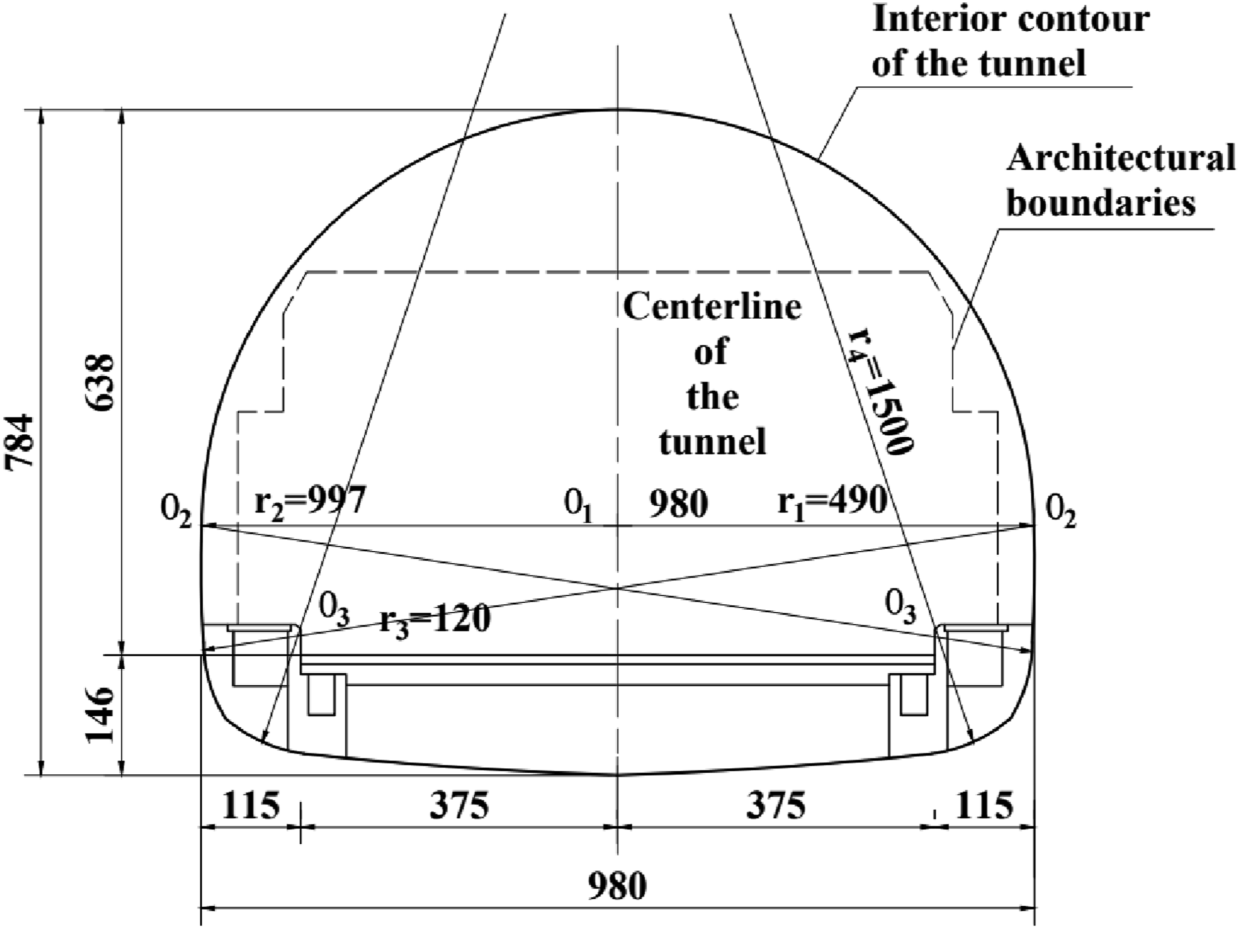
The depth of the tunnel has a significant impact on the settlement of surrounding buildings. In this study, the depth of the tunnel ranges from 30 m. The closest distance between the centerlines of the two tunnels and the centerlines of the surrounding buildings is 10 m, a critical parameter for assessing the influence of tunnel excavation on the buildings. The spatial relationship between the buildings and the tunnel is illustrated in Figure 2. During the numerical simulation, this study considers varying tunnel depths and distances from the tunnel to the buildings to comprehensively evaluate the impact of tunnel excavation on the settlement of surrounding structures. Diagram of the location of the building plan.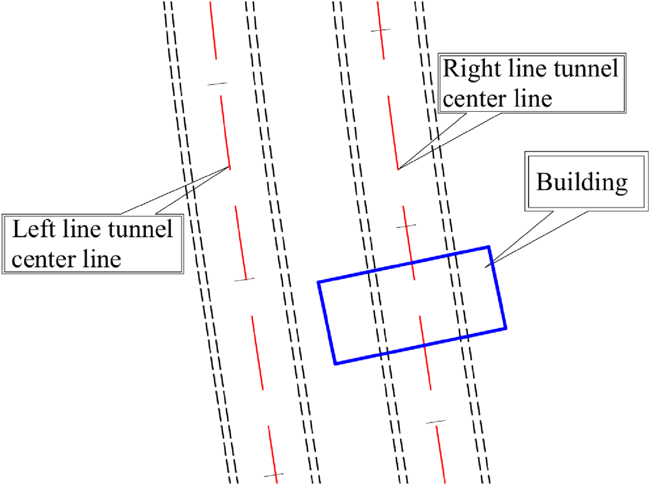
Finite element modeling
Basic functional relationships
In the model, the following fundamental functional relationships were employed to describe the behavior of soil and structural materials:
Constitutive Model: The Mohr–Coulomb failure criterion was used to describe the elastoplastic behavior of soil. This criterion takes into account the soil’s internal friction angle (ϕ) and cohesion (c), which are determined based on field and laboratory test data.
Stress-Strain Relationship: For structural materials, an elastoplastic model was adopted, which considers the material’s elastic modulus (E) and yield strength (fy).
Basic assumptions
The fundamental assumptions and explanations utilized in the model are as follows: (1) The material follows the Modified M-C failure yield criterion, accounting for unloading and reloading stiffness hardening of the soil. (2) Stress and strain within the materials and strata are assumed to vary within the elastic-plastic range during the loading process. (3) The influence of groundwater is disregarded due to the site-specific hydrogeological conditions, where preliminary assessments indicated negligible groundwater impact on the soil-structure interaction during tunnel excavation.
Parameter selection
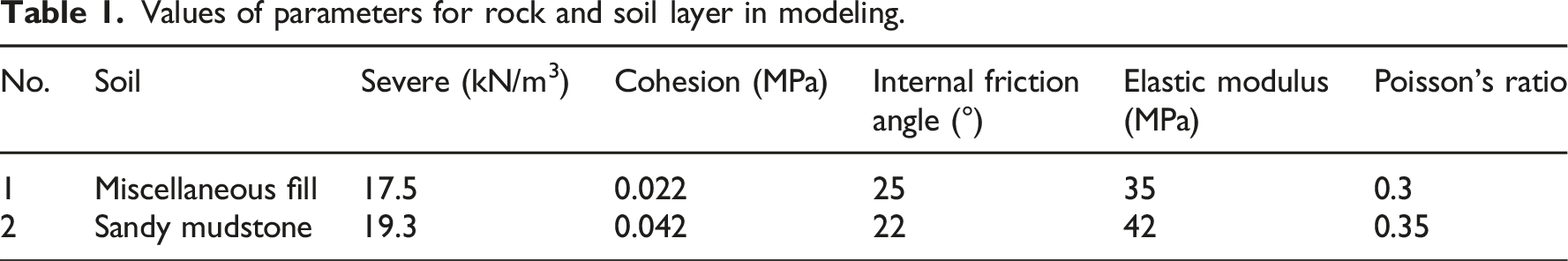
Values of parameters for rock and soil layer in modeling.
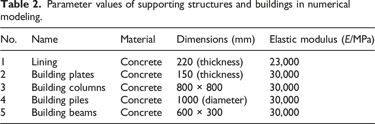
Parameter values of supporting structures and buildings in numerical modeling.
Finite element model
In this study, a numerical model was constructed using MIDAS/GTS software to analyze the deformation effects of tunnel construction on adjacent multi-story framed buildings. Given the research focus on the deformation patterns of buildings and the surrounding strata, the impact along the longitudinal direction of tunnel excavation was neglected, and a simplified two-dimensional plane strain model was established.
To mitigate the impact of boundary effects on the computational results, the model dimensions were set to 120 m × 60 m (refer to Figure 3). In the model, the thickness of the first soil layer is 10 m, and the thickness of the second soil layer is 50 m. The overall positional relationship between the building and the tunnel is shown in Figure 3. During the simulation of tunnel construction, the soil mass is divided into multiple sections, with different colors used to distinguish between various construction steps. The mesh size for both the tunnel and the building is 1 m, while the mesh size for the soil layers is 2 m. Schematic diagram of the model.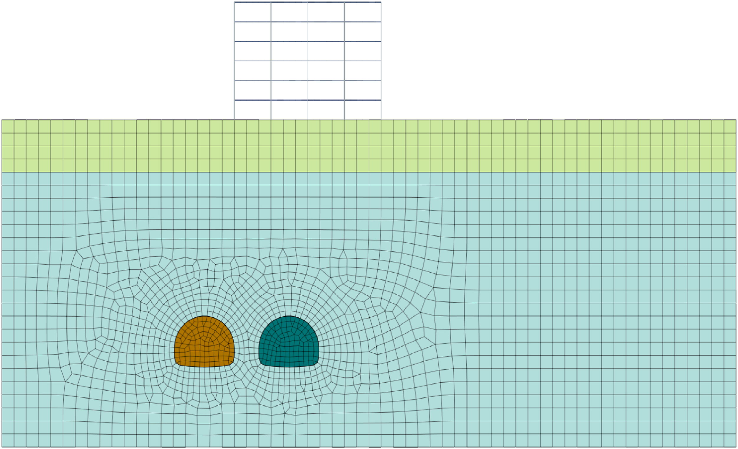
Boundary conditions and material parameters
(1) Boundary Conditions: The model coordinates were established in a Cartesian coordinate system, with the two-dimensional plane strain model set up on the XOY plane, where the Z-axis signifies the model’s depth direction. Within the XOY plane, the X-axis represents the horizontal direction, while the Y-axis signifies the vertical direction. Horizontal constraints are applied to both sides of the rock and soil materials within the model, with full constraints applied at the bottom and the top designated as a free surface. (2) Material Parameters: The aim of this study is to investigate the impact of tunnel excavation on the existing structural elements. To maintain uniformity in the variation patterns beneath the soil layers, the finite element model is endowed with identical types of properties. (3) In the model, it is assumed that the soil is homogeneous, meaning that the soil’s physical and mechanical properties are uniform in all directions. This assumption helps to reduce the complexity of the model, enabling more efficient calculations.
Settlement of building foundation
The allowable settlement standards for building foundations were determined based on the requirements of the engineering survey code and the specifications outlined in the Code for Building Deformation Measurement (JGJ7-2016). According to this code, the settlement limits for low, medium, and highly compressible soils are 20 mm, 40 mm, and 120 mm, respectively. Considering the elastic modulus E of the rock and soil mass as 10 MPa, categorizing it as highly compressible soil, the safety standard for building settlement was set at 120 mm.
To investigate building foundation settlement, each foundation was systematically numbered as illustrated in Figure 4. According to the numbering scheme in Figure 4, the first column (A1, B1, and C1) represents foundations closest to the tunnel, followed by the second column (A2, B2, and C2), with the third column (A3, B3, and C3) positioned relatively farther from the excavation zone. The spatial relationship between the building and tunnel configuration is visually presented in Figure 4. Relative position of the building to the tunnel.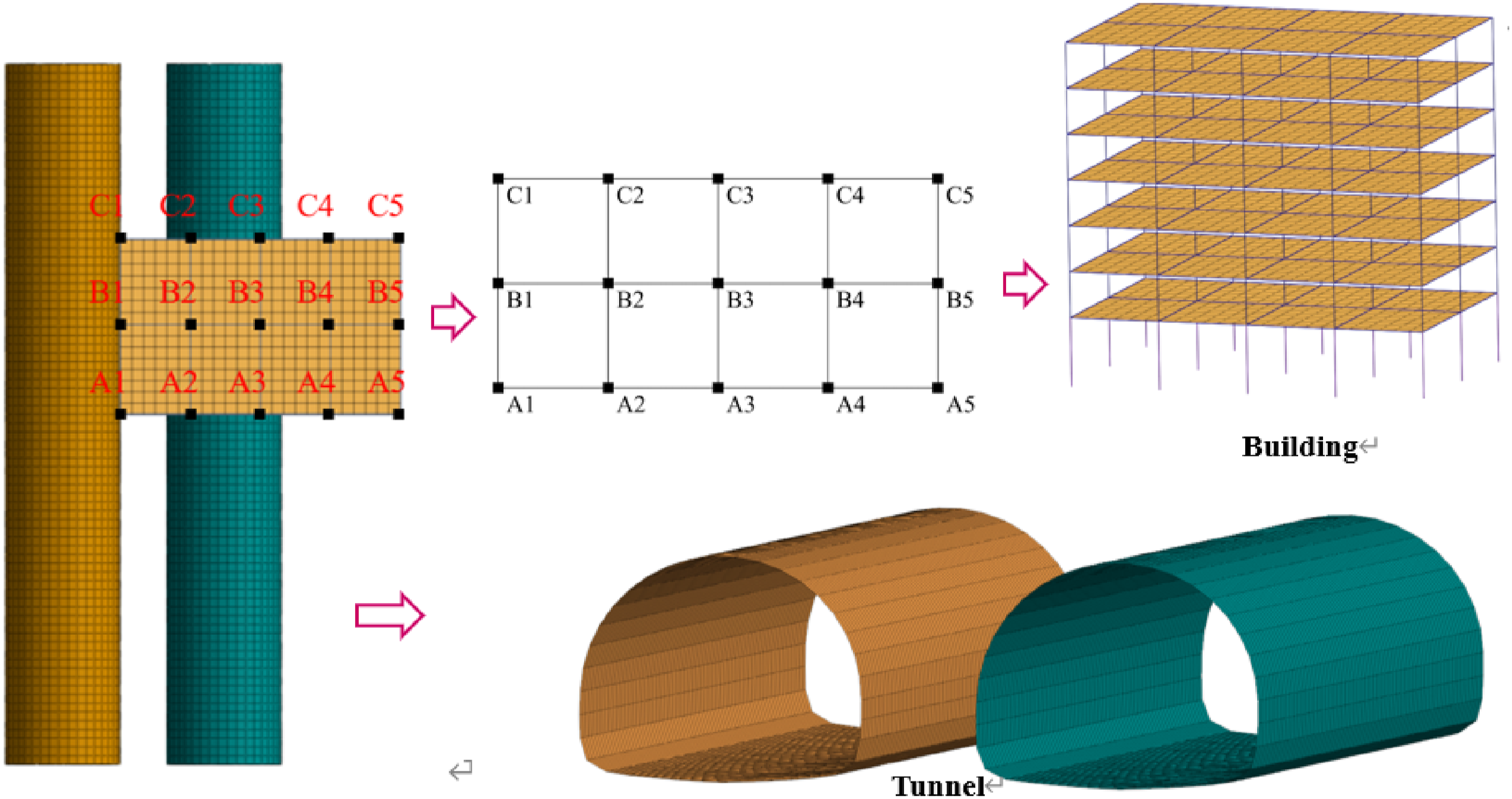
The tunnel excavation was conducted using the CD method. A model was established based on the actual tunnel excavation progress, with a current advance of 3 m. The specific construction simulation process included the following steps: Firstly, the initial state of the site was considered, and displacements were reset to zero to ensure accurate initial conditions. Subsequently, the construction of the structure was carried out; then, the simulation of the initial lining construction of the tunnel took place, including the process of initial covering of the tunnel walls. Finally, the simulation of the secondary lining construction of the tunnel was conducted. Through this series of steps, a comprehensive simulation and analysis of each stage of the entire construction process was achieved, providing a deeper understanding of the site’s dynamic response and structural changes. Ultimately, the settlement values of the building foundations were obtained, as shown in Figure 5 and Table 3. Settlement values at various points of the building foundation. Settlement values of the foundation of the building (mm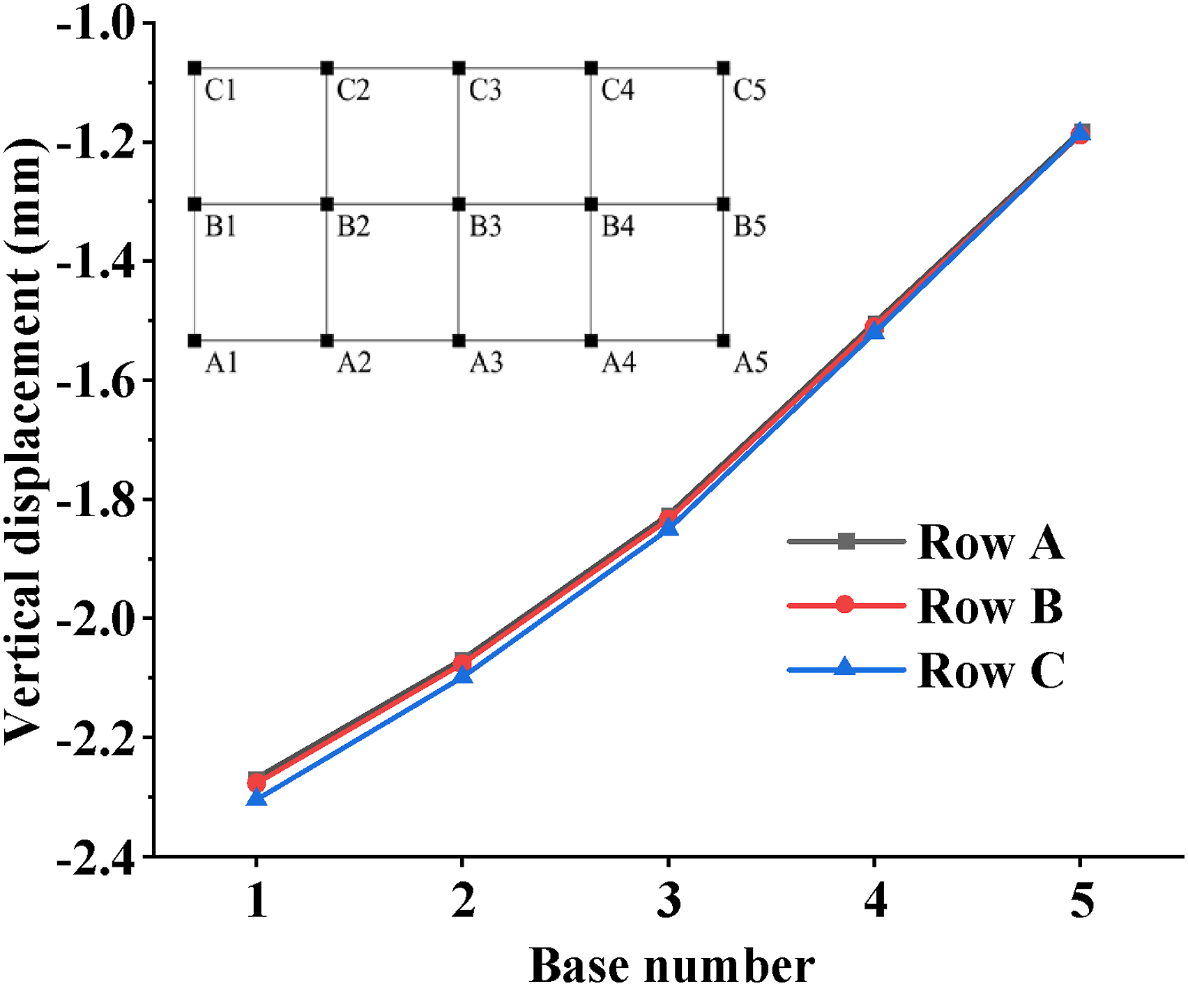
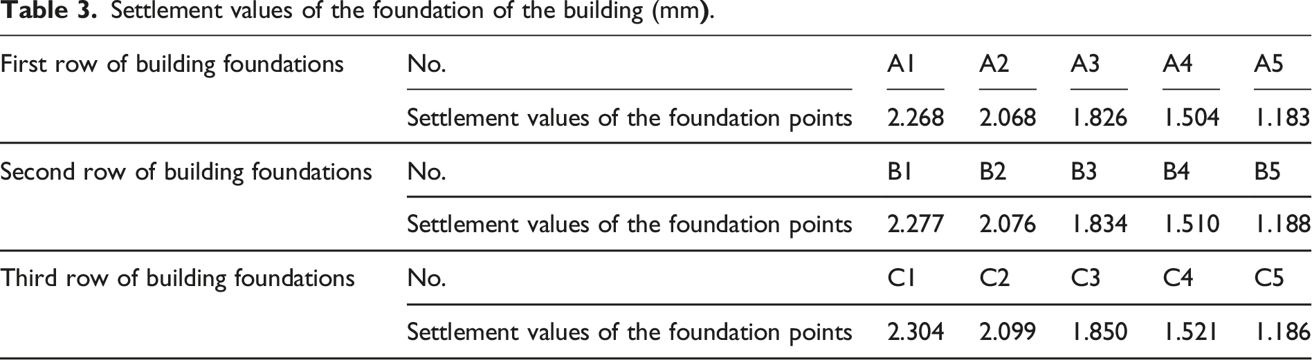
Based on the monitoring data analysis from Figure 5 and Table 3, the settlement of the building after tunnel excavation exhibits distinct spatial distribution characteristics: in the transverse direction along the tunnel axis, the closer the foundation is to the tunnel section, the larger the settlement value (the maximum cumulative settlement in row C reaches 2.4 mm). As the distance from the tunnel increases, the settlement decreases in a gradient manner (the minimum settlement in row A is 1.8 mm), consistent with the typical pattern of surface settlement caused by ground loss. The settlement curves of the three foundation rows show highly consistent linear slopes (settlement increments of 0.2–0.4 mm between adjacent foundations), indicating good homogeneity in the longitudinal distribution of geological conditions and upper loads in the field area.
From the perspective of inter-row differences, the building foundation settlement exhibits a significant hierarchical pattern of row C exhibits higher values than row B, which in turn exceeds row A, with stable settlement gradient differences of 0.2–0.3 mm between rows. The maximum inter-row difference of 0.6 mm occurs at foundation position 5. This regular settlement distribution indicates that the soil disturbance induced by tunnel construction has predictable transmission characteristics in the horizontal direction, with its influence range and attenuation pattern demonstrating engineering controllability. According to the safety standard value derived earlier, the maximum calculated settlement value of the building foundation is 2.257 mm, which is far below the safety standard value of 120 mm. Therefore, the settlement of the building is within a reasonable range, indicating that the ground environment is safe and controllable.
Analysis of key parameters of deformation in existing buildings
Effect of horizontal spacing on building deformation
The analysis results indicate that the settlement values of buildings during tunnel construction remain within a reasonable range. However, to ensure the safety and stability of the construction process, it is necessary to further investigate the influence of sensitive parameters induced by tunnel construction on the deformation of adjacent existing buildings.
This study primarily focuses on the horizontal distance between the tunnel and the building. The horizontal distance L between the right tunnel and the building axis is selected as 0 m (between the two tunnels), 5 m, 10 m, 15 m, 20 m, 25 m, 30 m, and 35 m. The ground deformation caused by tunnel excavation at different distances from the building is calculated. According to Table 3, during tunnel construction, the maximum settlement of the building foundation occurs at the column closest to the tunnel centerline, while the minimum settlement appears at the column farthest from the tunnel centerline. Therefore, it is sufficient to consider the settlement values at the points closest to and farthest from the tunnel centerline in each row (Figure 6–8). Settlement values at different horizontal spacings for A1 and A5. Settlement values at different horizontal spacings for B1 and B5. Settlement values at different horizontal spacings for C1 and C5.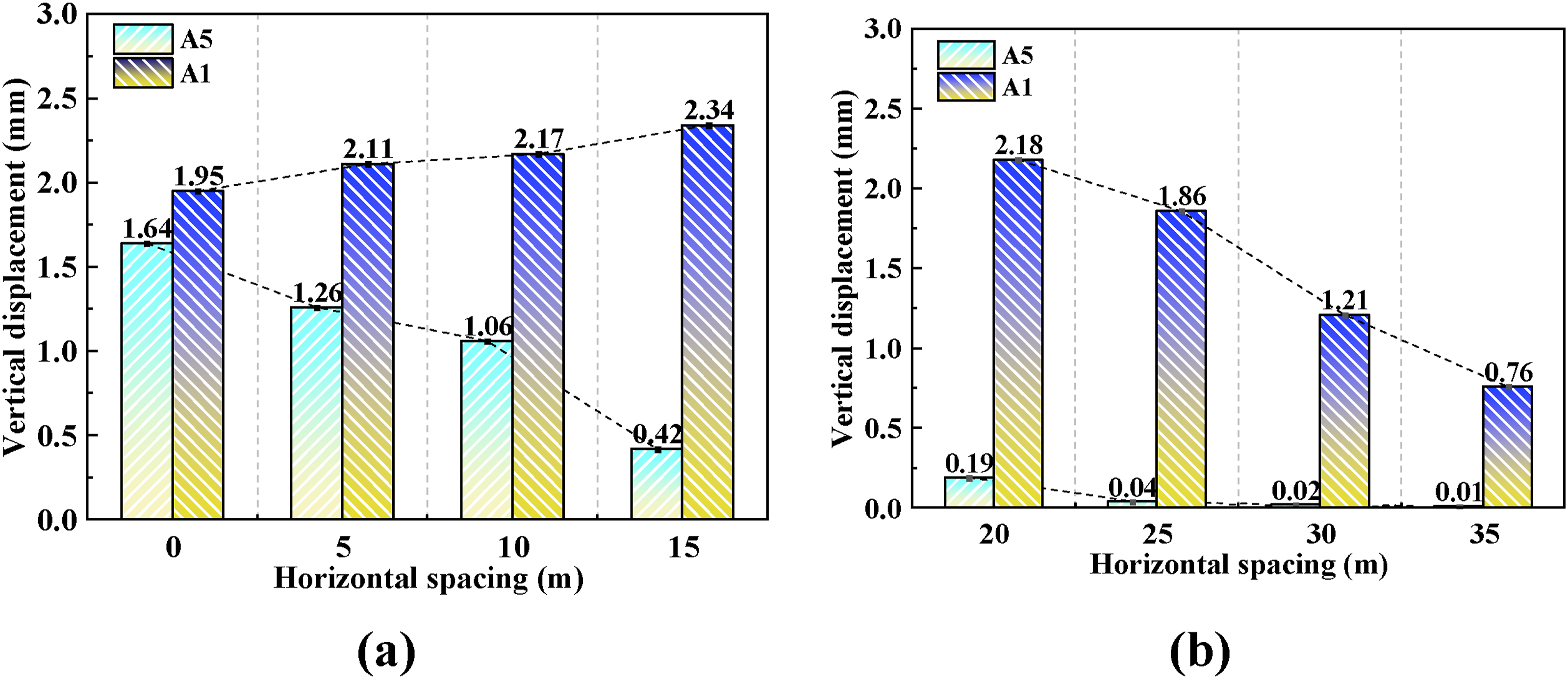
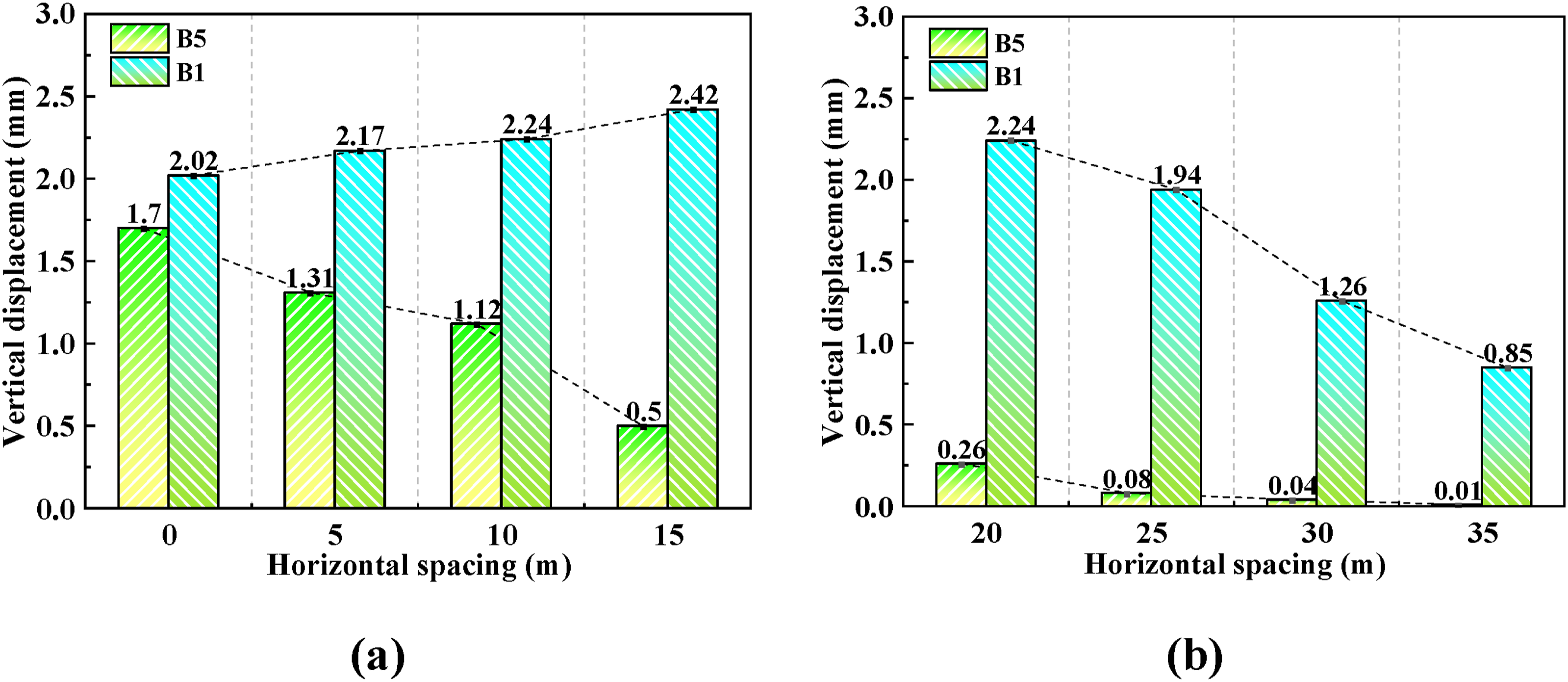
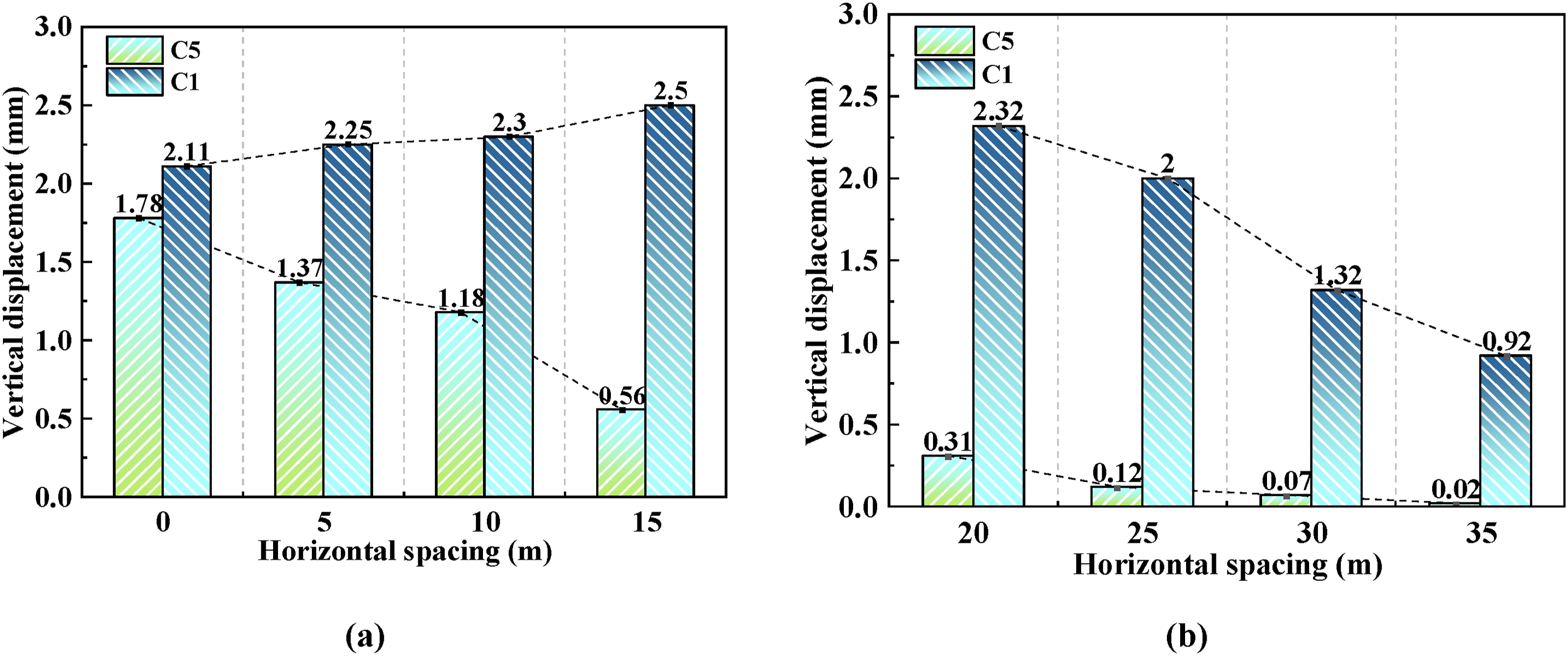
Due to the presence of buildings, the type of ground settlement curve is not axially symmetric, resulting in noticeable variations in ground settlement at building foundations.
From Figure 6–8, it can be concluded that when L is 0 m, the building is located between the two tunnels, and the settlement of the building foundation is relatively uniform, with a difference of less than 0.4 mm between the left and right settlement values in each row of the building, and the maximum settlement does not exceed 2.11 mm. When L is 10 m, the building axis coincides with the right tunnel axis, representing a case of the tunnel passing under the existing building. The maximum settlement is larger than that at L is 0 m. The excavation of the left tunnel causes unloading of the soil on the lower left side of the building, resulting in a settlement difference of 1.44 mm between the head and tail of the building foundation. When the right tunnel passes directly under the building’s central axis, the building experiences overall subsidence. Although the excavation of the left tunnel causes tilting, its impact on the existing building is relatively small. When L is 15 m, the settlement of the building caused by tunnel excavation is most pronounced, with a maximum value of 2.5 mm, and the existing building exhibits a tendency to tilt toward the tunnel excavation side, with the settlement difference between the head and tail of the building expanding to 1.94 mm. When L is 20 m, compared to L is 15 m, the overall settlement of the building decreases, but the settlement difference between the head and tail of the foundation increases to approximately 2.01 mm. When L is 25 m, both the settlement and the settlement difference between the head and tail of the building further decrease. As the horizontal spacing continues to increase, both the settlement and the settlement difference between the head and tail of the building show a decreasing trend.
Further insights from the figure indicate that between L is 0 m and L is 10 m, the building settlement is significant but relatively secure; however, between L is 15 m and L is 25 m, the substantial difference in settlement between the front and rear ends lowers the safety of the buildings. For L is 30 m to L is 35 m, the impact of tunnel construction on buildings is minimal, negligible at L ≥35 mm in terms of its effect on buildings.
In conclusion, the positional variation of buildings can significantly impact foundation settlement. In the context of a twin-tunnel scenario, when the edges of a building’s foundation align above a single tunnel, there is a significant difference in settlement between the front and rear ends of the building, indicating a higher risk. However, as the horizontal spacing further widens, the impact of tunnel excavation on buildings diminishes.
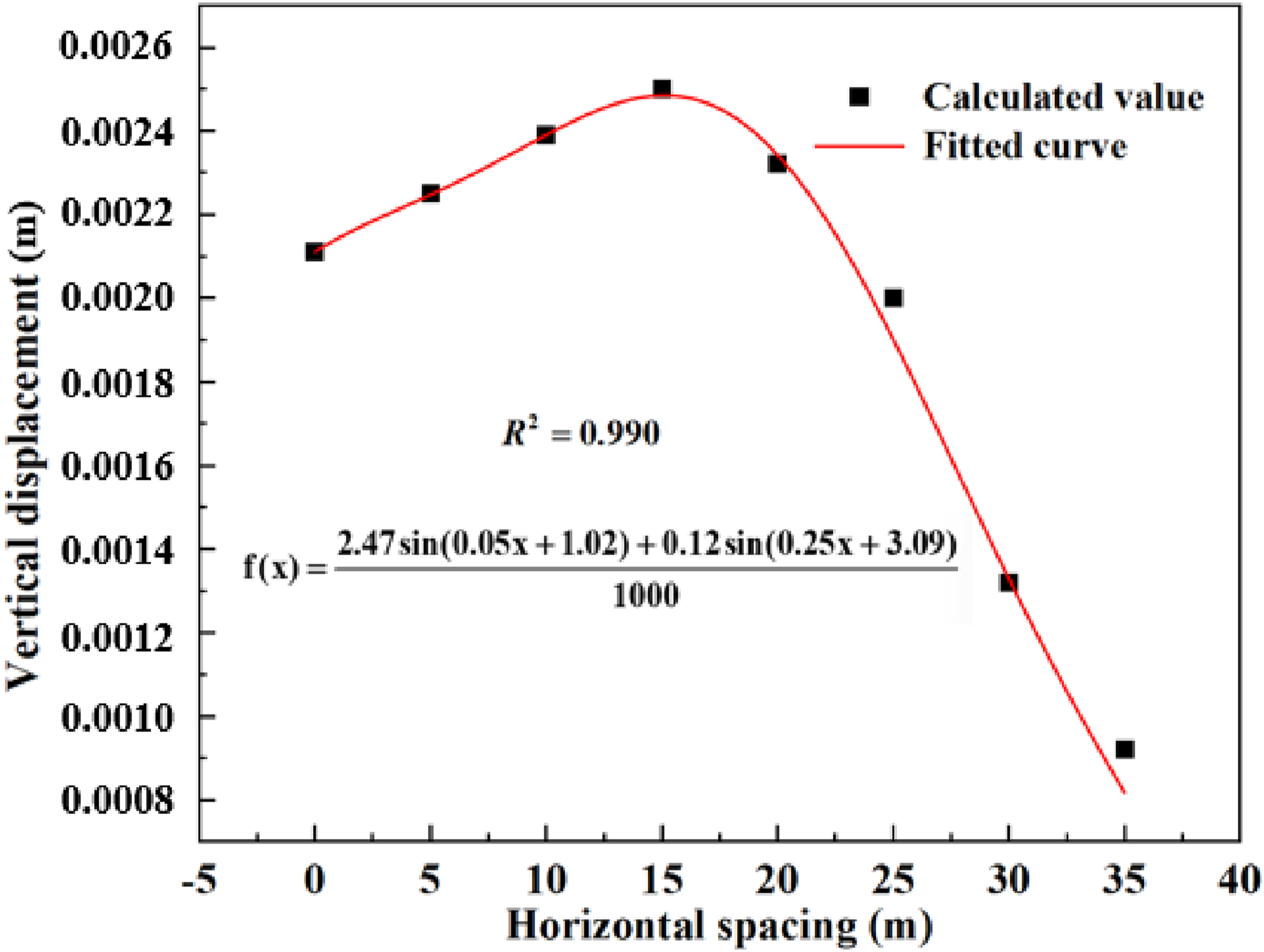
Based on finite element simulation data, mathematical formulas were fitted to describe the influence of tunnel excavation on surrounding buildings at varying horizontal distances. The results indicate that the impact of tunnel excavation on buildings at different horizontal distances can be effectively captured using a sine function, as shown in equation (1). Comparison of the fitting formula with the calculated values.
Impact of soil layer parameters on building deformation
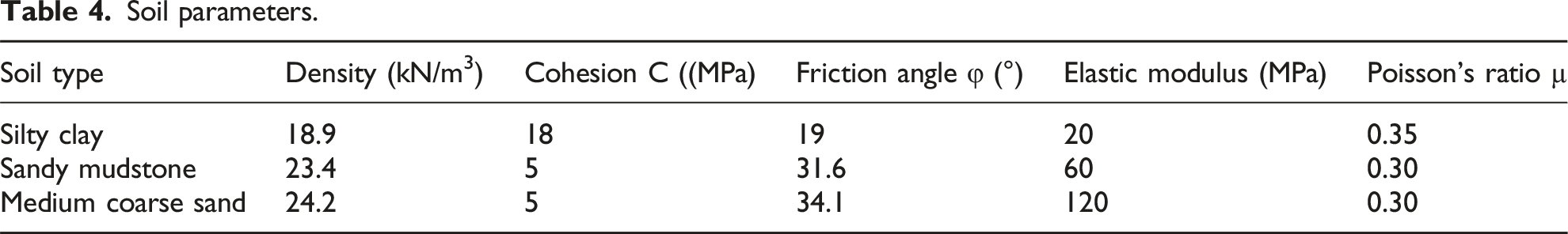
Soil parameters.
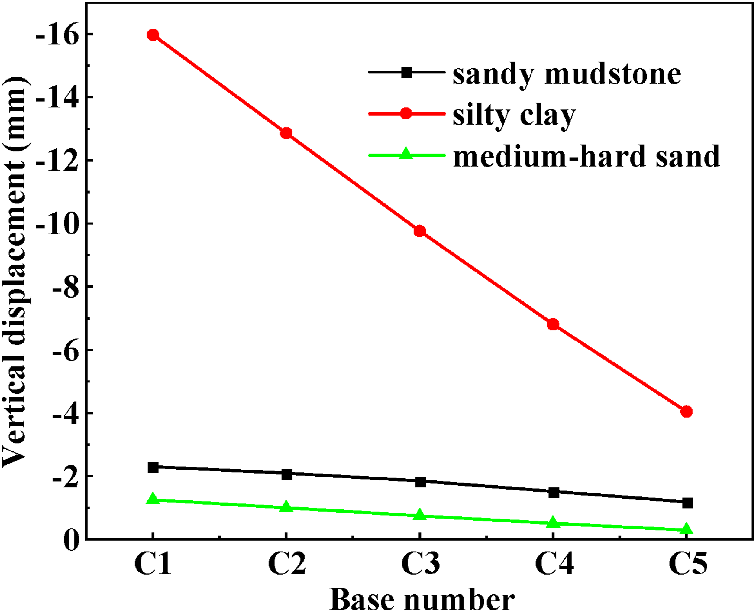
Deformation patterns of foundations with different soil parameters.
According to the data in Figure 10, as the soil quality deteriorates, the maximum settlement of the building increases significantly. When E is 20 MPa (the soil layer is silty clay), the maximum settlement reaches 15.9 mm, and a large settlement difference of approximately 11.9 mm occurs beneath the building foundation. In this case, the building is prone to cracking, indicating that the concealed excavation method is not suitable for poor soil conditions. If construction conditions only permit the use of the concealed excavation method, for small to medium-sized sections in weak strata, the CRD, CD methods, or the large pipe roof method can be considered. It is important to note that the full-face excavation method should not be used.
Influence of varied building heights
In addition to the horizontal spacing between tunnels and existing structures and the soil parameters, the differing heights of existing buildings also impact the deformation of structures. To investigate the influence of varying building heights on the deformation patterns of existing structures under the excavation of twin tunnels, four height scenarios are considered: H is 12 m, H is 18 m, H is 24 m, H is 30 m. Analyzing the deformation patterns of existing structures caused by tunnel excavation under different building height conditions, a uniform model parameter of L is 10 m was adopted.
From Figure 11, it can be concluded that when the building height H is 30 m, the vertical deformation of the building reaches its maximum value of 2.75 mm, and the settlement difference between the head and tail of the building is also the largest, approximately 2.29 mm, indicating that the building may exhibit a tendency to tilt toward the tunnel side. When H is 12 m, the maximum settlement value is about 2.17 mm, and the settlement difference between the head and tail of the building foundation is approximately 0.39 mm, which is the smallest among all working conditions. Therefore, as the height of the building increases, the settlement of the building gradually increases, and the corresponding risk of damage also rises. Displacement of row at different building heights.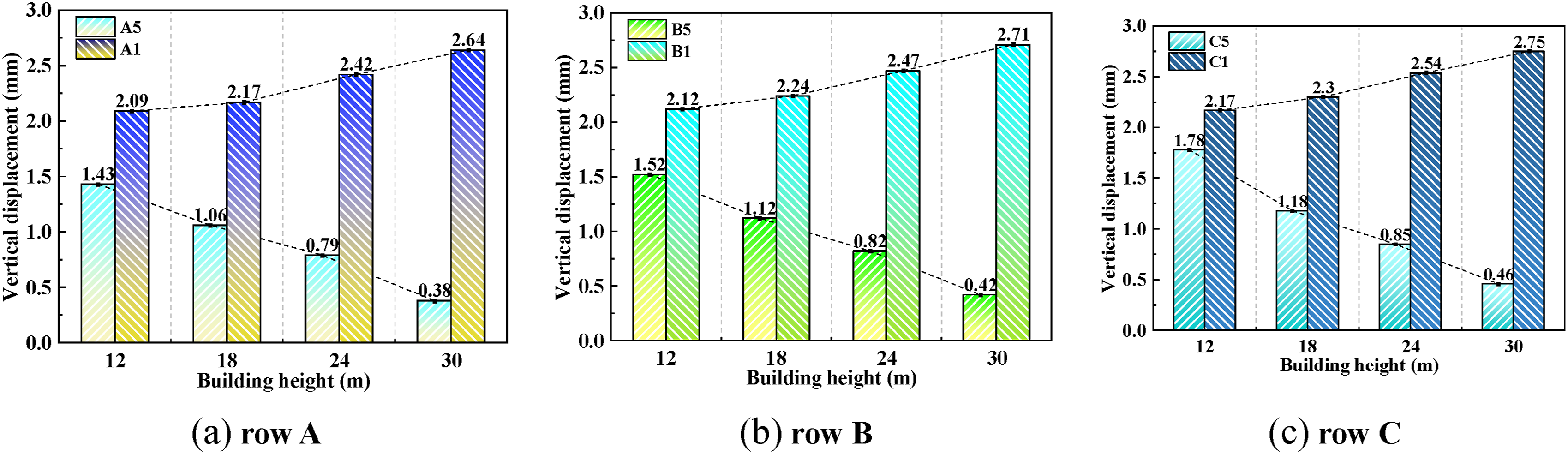
Conclusions
This study, integrating practical engineering considerations, investigates the deformation effects of tunnel excavation on adjacent buildings using numerical simulation techniques. It validates the stability of structures in practical engineering scenarios. Furthermore, an analysis of the response patterns of different key parameters on building deformation yields the following conclusions: (1) The spatial position effect is significant: the horizontal spacing between the building and the tunnel is the core factor influencing the deformation distribution. When L is 0 m (the midpoint between the two tunnels), the settlement of the building exhibits a uniform distribution, with a maximum difference of only 0.4 mm. When L is 15 m (directly above a single tunnel), the settlement difference between the head and tail reaches 1.94 mm, forming a pronounced tilting trend. The established displacement prediction formula (Equation (1)), through the superposition of sine functions, effectively characterizes the nonlinear relationship between the horizontal distance and the displacement response (R2 > 0.95). (2) The sensitivity of the formation exhibits significant differences: the elastic modulus of the soil has a decisive influence on deformation. Under silty clay formation (E is 20 MPa), the maximum settlement reaches 15.9 mm, representing a 572% increase compared to sandy mudstone formation (E is 60 MPa). In this case, the settlement difference between the head and tail reaches 11.9 mm, far exceeding the safety standards for buildings. Research indicates that when the soil elastic modulus is below 30 MPa, special construction methods such as the CRD method or the large pipe roof method are required to control deformation. (3) The coupling effect of building height is evident: increasing building height enhances the interaction between load and formation. The maximum settlement of a 30 m high-rise building (2.75 mm) increases by 26.7% compared to a 12 m low-rise building (2.17 mm), and the settlement difference between the head and tail increases from 0.39 mm to 2.29 mm. However, the horizontal displacement remains consistently less than 12% of the vertical displacement, indicating that the structure primarily bears asymmetric vertical loads. (4) The engineering safety threshold is defined through multi-condition comparisons, with a horizontal spacing of 35 m identified as the boundary threshold. At this distance, the building settlement attenuates to 0.18 mm, and the settlement difference between the head and tail is less than 0.1 mm. For highly compressible formations (E less than 30 MPa), it is recommended to employ dynamic grouting compensation technology to control the formation loss rate within 0.5%. The 35 m safety spacing threshold has been validated for tunnels with an H of around 2.5D. For shallow tunnels (H less than 1.5D), spacing should be scaled proportionally to burial depth and soil stiffness.
The limitations of this study primarily lie in the simplification of spatial effects by the two-dimensional model and the discrepancy between the assumption of homogeneous soil and on-site conditions. Future research will develop a three-dimensional refined model, integrate BIM monitoring data, and consider the coupling effects of complex loads such as seismic motions to enhance the engineering applicability of the prediction model.
Footnotes
Funding
The authors disclosed receipt of the following financial support for the research, authorship, and/or publication of this article: This work was supported by the China Postdoctoral Science Foundation (No. 2023MD734186), the Chongqing Doctor Direct Online Fund (CSTB2023 NSCQ-MSX0208, CSTB2022NSCQ-MSX0518), Chongqing Technological Innovation and Application Development Project (CSTB2022TIAD-KPX0144), Chongqing Construction Science and Technology Plan Project: (Chengkezi 2023 No.1-1).
Declaration of conflicting interests
The authors declared no potential conflicts of interest with respect to the research, authorship, and/or publication of this article.