



Abstract
As electric vertical take-off and landing (eVTOL) concepts and urban air mobility gain prominence, the mitigation of propeller noise has become essential. This study presents a comprehensive assessment of acoustic prediction methodologies, focusing on the application of both Formulation-1A and the more recent Formulation-1C of the Ffowcs Williams-Hawkings (FWH) equation. The work demonstrates the use of steady-state Reynolds-averaged Navier-Stokes (RANS) simulations with a single rotating frame (SRF) approach for efficient acoustic analysis, enabling the transformation of steady flow solutions into time-varying acoustic surface data. The methodology is implemented as a new class within the open-source libAcoustics library for OpenFOAM, leveraging its parallelization capabilities. Validation with experimental data and comparison against numerical results were performed for a range of propeller configurations. Comparative analysis with direct noise computation (DNC) highlights the improved accuracy of Formulation-1C, especially in scenarios with ambient flow, and demonstrates the limitations of Formulation-1A in such conditions. The results confirm the robustness of the proposed framework for propeller noise prediction across a range of operating regimes.
Keywords
Introduction
The accurate prediction of noise for propellers and other aircraft components plays a key role in development of overall quieter air vehicles. The development of numerical tools and experimental techniques that can predict the sources and propagation of acoustic pressure waves efficiently and with higher accuracy has become essential and remains active field of research necessary for aircraft development and certification. Both aerodynamic and acoustic performance analysis can be combined in an optimization framework for designing low noise systems. 1 Most of the methodologies involving acoustic analysis utilize, as input, aerodynamic data which is generated either through experiments or through numerical analysis such as computational fluid dynamics (CFD) and so the accuracy of acoustic analysis depends on the fidelity of the preceding aerodynamic analysis. 2 There are two main approaches which numerical noise prediction frameworks can generally follow: direct noise computation (DNC) approach and surface integration-based hybrid approach. In the first approach i.e. DNC, high-fidelity transient CFD simulations are performed using large eddy simulations (LES) or detached eddy simulations (DES) turbulence models and pressure fluctuations are stored during simulation in pre-defined probes on which spectral analysis is performed later.3–5 Although the DNC approach offers high accuracy, it is mostly restricted to near-field noise prediction due to requirement of detailed mesh and large computational resources. The second approach, involving volume and surface integral-based methodologies, utilizes Lighthill’s analogy6,7 which is derived from Navier-Stokes equations. The two major extensions are Curle’s analogy 8 which is restricted to static solid boundaries and Ffowcs Williams-Hawkings (FWH) methodology 9 which is more general and caters for moving medium and arbitrary movement of both permeable and impermeable surfaces. These analogies, involving surface integrals, can predict noise propagation in the farfield with less computational time. FWH surface-integral methodology has been widely applied for far-field broadband jet noise prediction 10 and have also been successfully used for propeller and rotor acoustic analyses, including recent low-Reynolds-number propeller studies. 11 Apart from the aforementioned time-domain approaches, low fidelity frequency-domain based acoustic theories for propeller noise prediction have also been formulated by Gutin, 12 Deming 13 and Hanson. 14
Comprehensive experimental and numerical research has been conducted in parallel over the years for characterization of propeller blade noise. Purcell 15 conducted experiments on scaled down version of UH-1H rectangular planform rotor operating at hover condition and high tip speed with transonic flow. A geometrically similar rotor was used by Boxwell et al. 16 in their experiments to measure impulsive noise for both hover and forward flight conditions. Farassat and Brentner 17 used the experimental results by Purcell to perform numerical comparison between Formulation–1A of FWH equation and Kirchhoff’s Formulation, finding Formulation-1A to perform better even if the surface is permeable. Later, Morgans et al. 18 extended the analysis for non-lifting forward flight. Extensive wind tunnel tests were also performed, both aerodynamic and acoustic, for designing a fuel-efficient group of NASA’s SR-series turboprop propellers.19–23 Tan et al. 24 used transient CFD results, whereas, Gennaro et al. 25 used steady-state CFD results of SR-2 propeller to obtain noise propagation using Formulation–1A and its steady-state version respectively. However, it was noted by Gennaro et al. 25 that few corrections were required in order to properly compare the steady-state acoustic results with experimental data. Marinus et al. 26 developed a novel truncated methodology for dealing with the problem of sonic singularity and performed acoustic analysis utilizing steady-state CFD results of SR-3 propeller geometry. A detailed comparison study of different frequency-domain based acoustic methods was performed by Herniczek et al. 27 for nine published experiment cases including the case of SR-2 propeller. They concluded that Hanson’s model 14 exhibited the maximum accuracy. Both experimental and numerical analysis were performed by Casalino et al. 11 with the purpose of setting a benchmark problem for low Reynolds number propeller acoustics. In the numerical part of their study, they utilized high fidelity as well as low-fidelity computational models. Recently, Baskaran et al. 28 performed detailed experiments to study the effect of number of blades on propeller broadband noise.
While Formulation–1A remains conventional and produces results within acceptable tolerances, its inherent limitation lies in its inability to account for ambient velocity effects. To address this, Najafi et al. 29 proposed a modified version, termed Formulation–1C, which explicitly incorporates ambient velocity considerations. Garrick Triangle (GT) Formulation 30 is the simplified version of Formulation-1C for stationary surfaces. Brès et al. 31 applied the GT method to conduct acoustic analysis of a fan by constructing a stationary permeable surface around it. Building on this work, Zhang et al. 32 developed an open-source FORTRAN code which integrates GT Formulation and leverages the OpenMP parallelization to increase computational speed of acoustic analysis. Although Formulation–1A has been used to perform acoustic analysis on steady-state CFD data, to the best of the authors’ knowledge the Formulation-1C has never been utilized in similar manner. Applying Formulation–1C to steady-state CFD data enables rapid and computationally efficient evaluation of propeller noise in the presence of ambient flow, overcoming the limitations of earlier methods and allowing for usage of both impermeable and permeable surface data for inclusion of nonlinear noise sources. This research brings a notable novelty to the existing literature, as it is the first to demonstrate and validate the use of Formulation–1C on steady-state numerical data for propeller aeroacoustics analysis.
The aims of this study are addressed through the following key objectives: 1. Summarize the foundational acoustic analogy forming the basis of the presented approach (Subsection: Acoustic analogy). 2. Establish the distinctions between Formulation-1A and Formulation-1C within the context of steady-state computational analysis (Subsection: Formulation – 1A and formulation – 1C). 3. Outline the range of verification and validation cases selected to demonstrate the effectiveness of the proposed methodology (Section: Verification and validation). 4. Highlight the comparative evaluation against both conventional Formulation-1A results and DNC from unsteady (transient) analysis (Section: Formulation comparison). 5. Integrate the developed methodology as a dedicated module within the libAcoustics suite for OpenFOAM, exploiting native parallel processing to enable efficient acoustic data handling.
Acoustic analysis methodology
In this section, the foundational FWH theory, which serves as the backbone of our methodology, is detailed. Both its convective and non-convective formulations are explained. Subsequently, the two principal integral solution Formulation-1A and Formulation-1C are discussed. The section concludes with a description of the steady-state methodology, integrating these developments into the overall computational approach.
Acoustic analogy
The FWH equation is derived from Lighthill’s acoustic analogy and is also its most widely used form. The differential form of FWH equation used for permeable surface is given as:

The first term on right hand side of FWH equation is monopole source and contributes to loading noise, whereas the second term is dipole source which contributes to thickness noise. Dirac delta function (


The tensor terms (
Formulation – 1A and formulation – 1C
Integral formulations of the FWH equation, both non-convective and convective forms, are essential for practical implementation. Formulation–1 A, introduced by Farassat and Succi
33
for both permeable and impermeable surfaces, is derived from the non-convective FWH equation. The pressure perturbation (

In the sum,



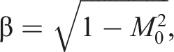
For moving surfaces, the components of the Mach vector

Formulation – 1C is derived from convective form of FWH equation by Najafi et al.
29
and the respective thickness and loading noise terms are defined as:




In this formulation, the geometric distance




Steady-state acoustic analysis methodology
Acoustic analysis, whether using DNC or surface integral methodologies like FWH, requires transient pressure and velocity field data on the surface as input. Generating this data through CFD is computationally expensive, particularly with high-fidelity models like LES or direct numerical simulation (DNS). For propellers, LES is essential to capture broadband noise by resolving turbulent fluctuations, while unsteady RANS (URANS) suffices for low-frequency tonal noise.
34
However, URANS simulations remain time consuming. When propeller loading (i.e., pressure and velocity distributions) remains stable, a steady-state RANS model, with a single rotating frame (SRF) approach can be employed.
35
The converged flow fields can then be sampled on the FWH surface and rotated along with it to generate time-varying data for surface integration. The primary limitation of this methodology is its inability to accurately capture complex effects during noise-generating such as blade vortex interaction (BVI),36,37 cavitation,
38
installation effects,39,40 interference between counter-rotating propellers,
41
and ground effects.
42
These events involve highly unsteady and transient flow characteristics, which are not effectively modeled using a steady-state CFD. Sampled scalar fields (e.g., density and pressure) require no rotation, while vector fields, including fluid velocity

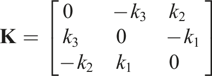
The rotated vector fields can be obtained by multiplying the rotation matrix with the vector field e.g.,

Field variables on the permeable FWH surface were sampled using OpenFOAM’s surfaceSampling utility, which applies cell-centered inverse-distance weighted linear interpolation. The sampled surface data was obtained directly from the steady SRF solution.
Verification and validation
In the present work, four cases were used to verify and validate the proposed methodology. The verification case involves baseline monopole and dipole acoustic sources, and the remaining three cases focus on propeller studies, with the results from the Formulation-1C method validated against existing experimental and numerical data. For the validation cases, steady-state CFD simulations were performed using a single reference rotating frame (SRF) approach in StarCCM+. The
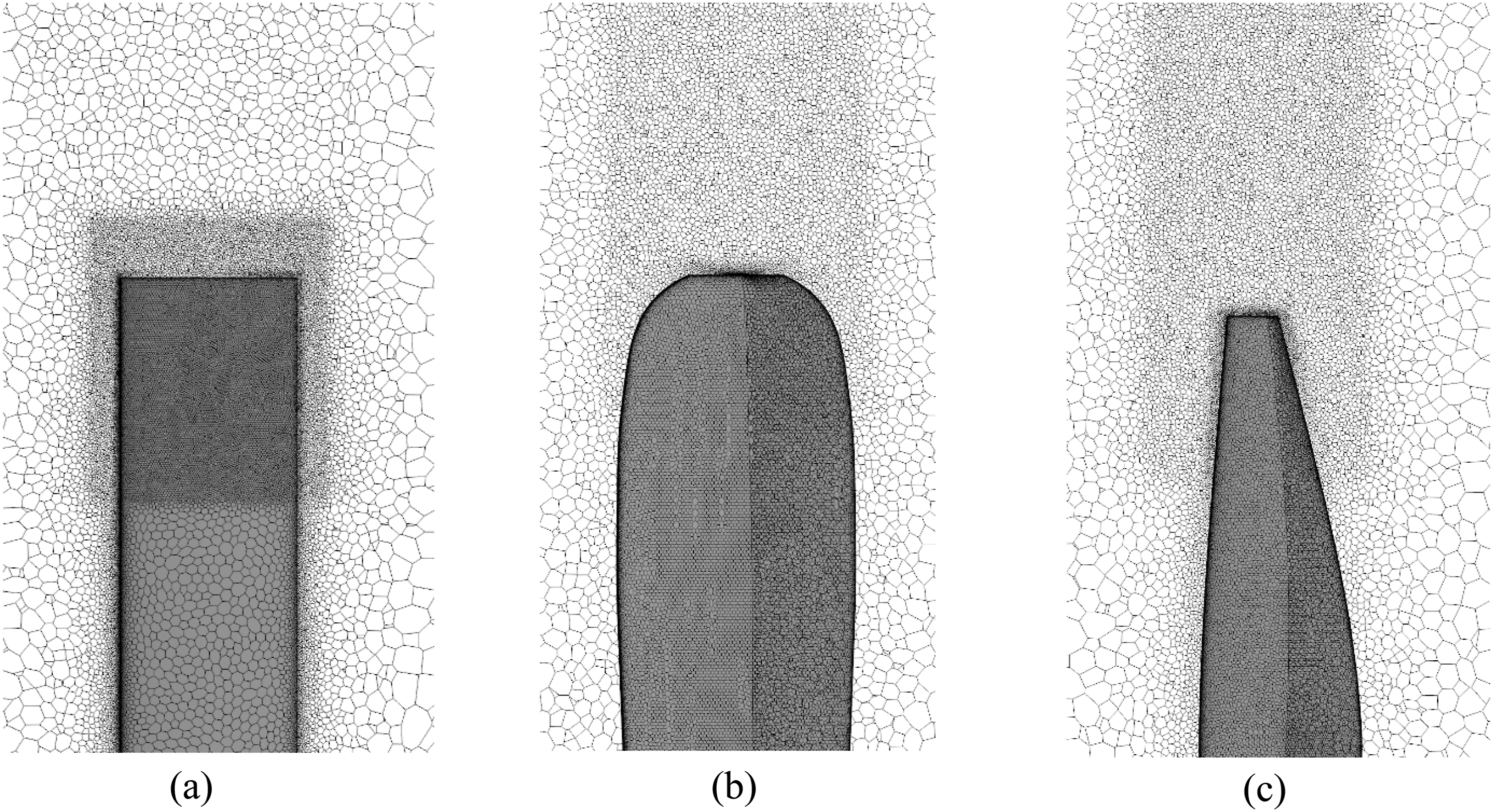
The computational domain was cylindrical, with a radius of 10 and a length of 20 propeller radii, centered on the propeller. For two-bladed geometries (UH-1H and Casalino Propeller), a half-domain with periodic boundaries was used, while a quarter-domain with periodic boundaries was implemented for the four-bladed SR-2 propeller. Surface meshing on the blades maintained a baseline cell size of (a) Semi-cylindrical computational domain used for the UH-1H and TUDelft Casalino propeller cases; (b) Quarter-cylindrical domain employed for the SR-2 propeller case. Tip mesh for propeller cases: (a) UH-1H tip mesh showing localized refinement for shockwave resolution; (b) SR-2 propeller; (c) TUDelft Casalino propeller.
Baseline monopole and dipole
Verifying the methodology and code functionality for transient analysis using baseline cases, such as monopole and dipole acoustic sources, is essential. These sources were selected for their simplicity and availability of their exact analytical solutions which can be derived without computationally intensive simulations. Furthermore, the superposition of monopole and dipole sources effectively models most real-world complex acoustic phenomena, making them ideal for verification. Formulation-1C’s unique capability to predict noise propagation in moving media, requires validation through analytical solutions for monopoles and dipoles in such environments. The potential function solutions for both sources are given below, as detailed in the work of Najafi et al. 29
Monopole

Dipole

The pressure and velocity perturbation can be calculated using the following expressions:


The FWH surface was defined as a sphere with a 1 m radius, with surface data computed using the equations (10)–(13). Verification involved 20 receivers arranged in a 30 Directivity pattern Directivity pattern  ): Formulation-1C results; (
 ): Analytical reference.): Formulation-1C results; (): Analytical reference.
Since the data on the FWH surface and the pressure data at the receivers were both computed using the same analytical equations, the resulting error is almost negligible. This comparison confirms that the methodology performs correctly for both monopole and dipole sources. It can also be observed that, in moving flow cases,
UH-1H rotor
The UH-1H rotor has been extensively used in experimental studies for thorough categorization of both thickness and loading noise components. As a result, a substantial amount of experimental data is available for comparison with numerical studies. The rotor features a simple rectangular planform with a NACA 0012 airfoil section, a radius of 1.045 m, and an aspect ratio of 13.7, as described in Purcell.
15
The test model was a CAD geometry of the UH-1H rotor with the permeable surfaces. Relative Mach number and pressure contours for the UH-1H rotor: (a) relative Mach contour at 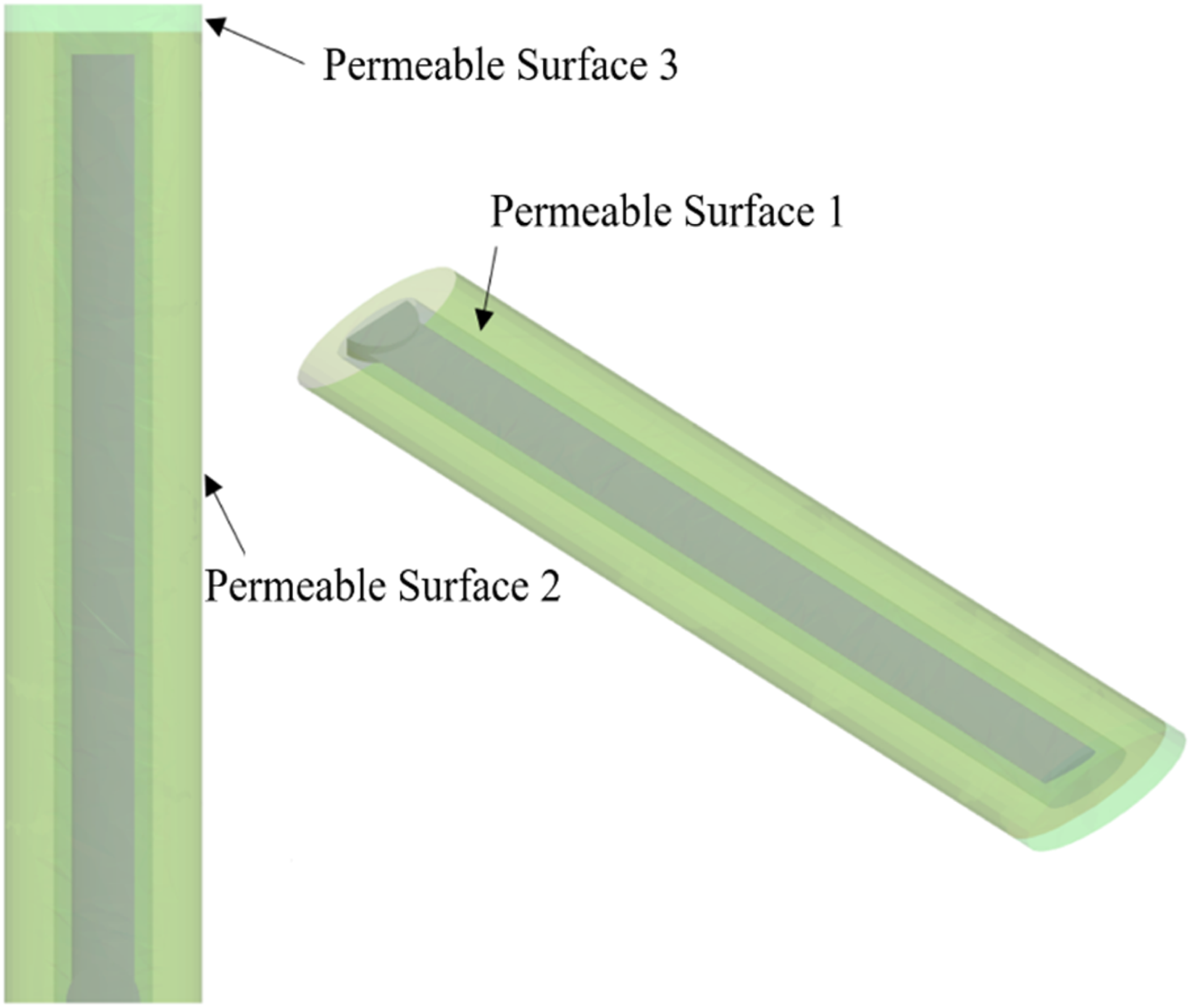
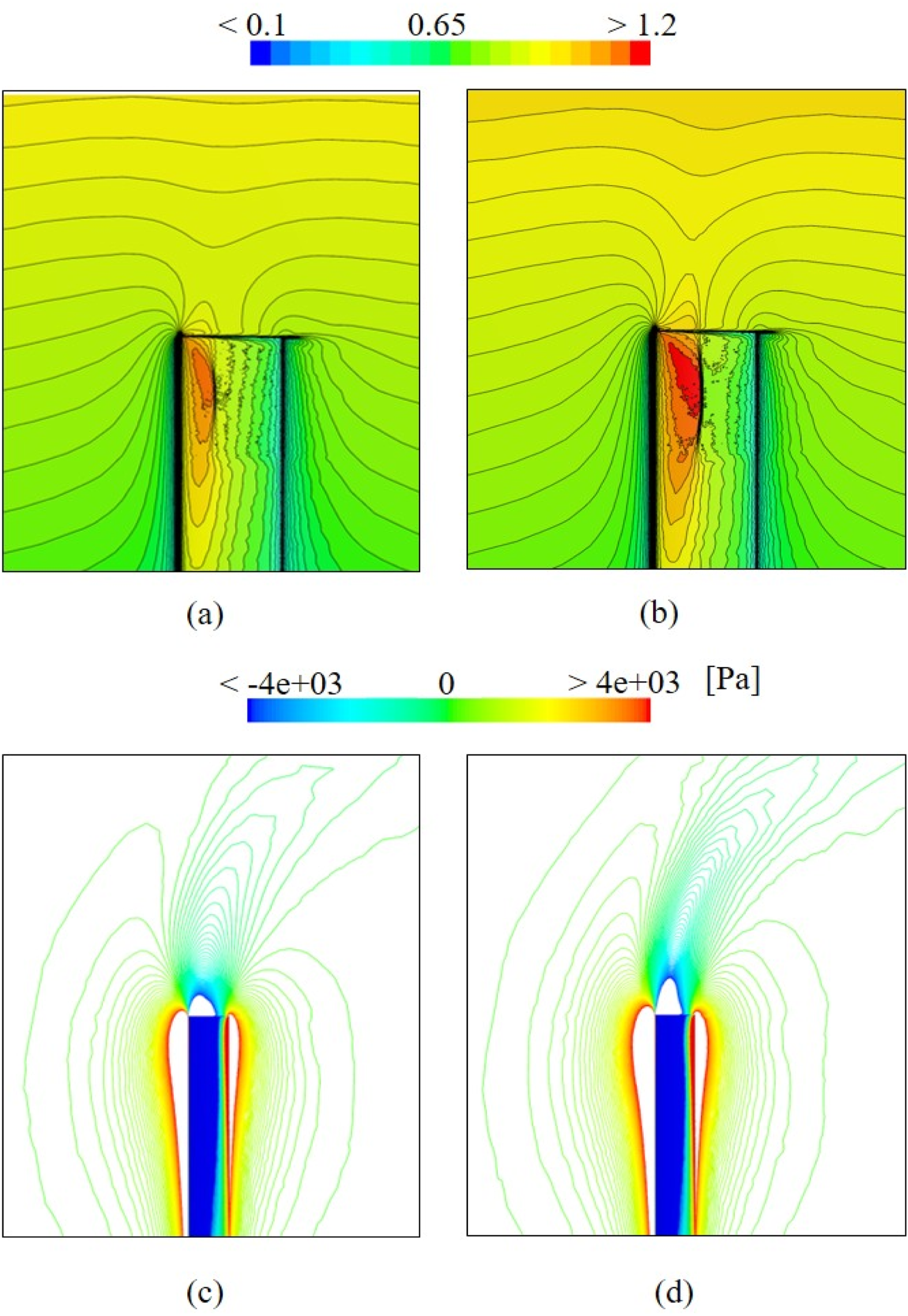
Analysis of the pressure drop profile at an in-plane receiver positioned 
 ): Permeable surface 1 (Current); (
 ): Permeable surface 2 (Current); (
 ): Permeable surface 3 (Current); (
 ): Wing (Morgans
 ): Experiment (Purcell
SR-2 propeller
The validation case involving the SR-2 turboprop propeller has been selected to allow the feasibility of the formulation to be assessed on complex propeller geometries, as well as the presence of upstream velocity in the corresponding experimental data. The geometry utilized in this study is a 4-bladed propeller with diameter of 0.591 m. The CAD geometry and distribution of geometric parameters with respect to radial ratio (a) SR-2 CAD geometry; (b) SR-2 geometric parameters distribution.
22
Experimental setup for SR-2 propeller noise measurements by Soderman and Horne
22
: (a) front view; (b) top view. Comparison of experimental and numerical results for SR-2 propeller.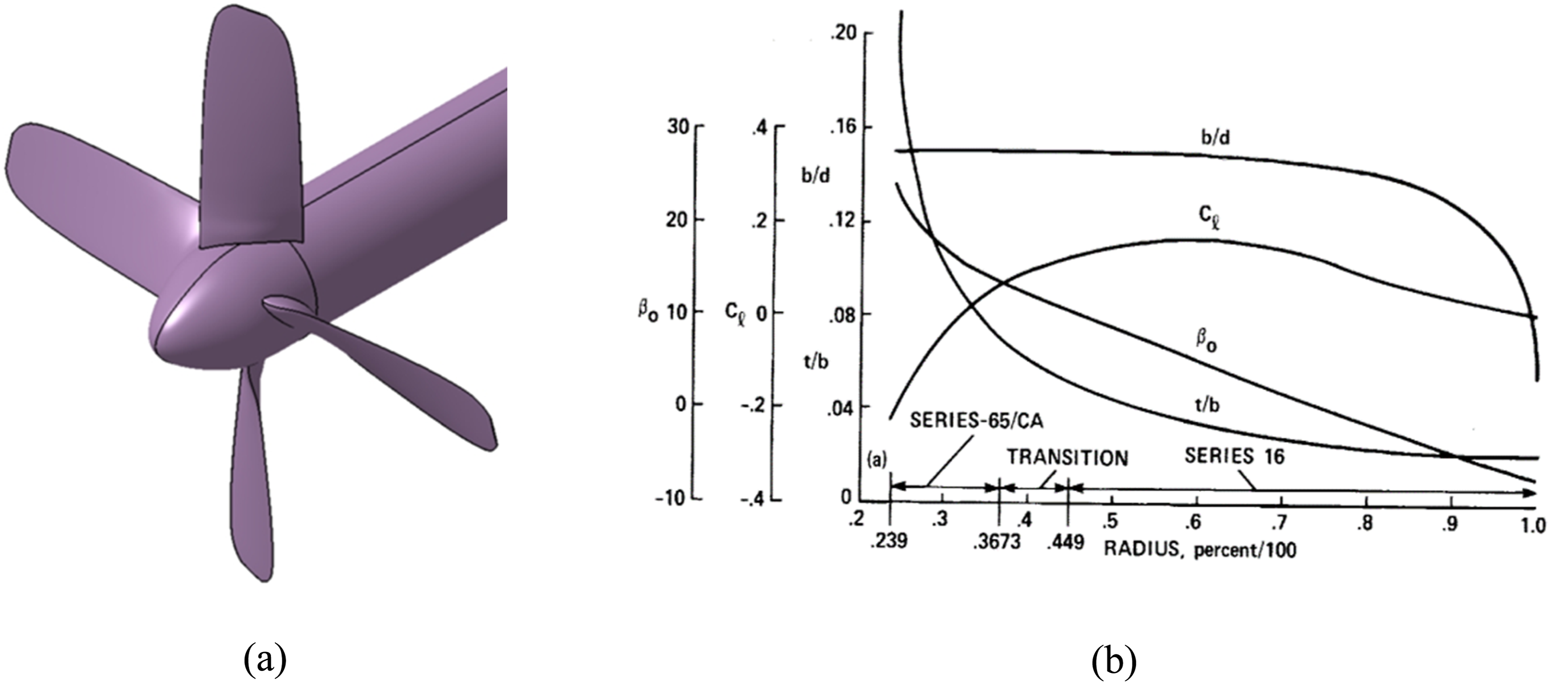


The maximum error for Sound pressure level (SPL) as a function of  ): Formulation-1C (Impermeable surface); (
 ): Formulation-1C (Permeable surface); (
 ): Gutin (Frequency method)
27
; (
): Gutin (Frequency method)
27
; ( ): Hanson (Frequency method)
27
; (
): Hanson (Frequency method)
27
; ( ): Experimental results.
22
.
): Experimental results.
22
.
Casalino et al. study (TUDelft)
Casalino et al.
11
conducted a series of experiments in TUDelft A-Tunnel on small-scale propellers designed typically for eVTOL applications. Their primary objective was to provide a comprehensive comparison of acoustic analysis results obtained from experimental measurements, high-fidelity large eddy simulations (LES), and low-fidelity blade element momentum theory (BEMT) calculations. The inclusion of this validation is essential to test the proposed methodology’s accuracy for propellers operating at low subsonic speeds. The experimental setup depicted in Figure 11 illustrates the placement of a vertical receiver array located at a distance equal to four times the propeller diameter. This array consists of approximately 13 uniformly spaced receivers. Notably, this configuration differs from the conventional arc arrangement typically used in such experiments. The two-bladed propeller has a radius of 0.15 m, with its geometric details present in Casalino et al.
11
The operating conditions used for both the experiments and numerical validation are presented in Table 2. It should be noted that the propeller RPM was held constant at 5000. Experimental setup used by Casalino et al.
11
for propeller noise measurements. Operating conditions.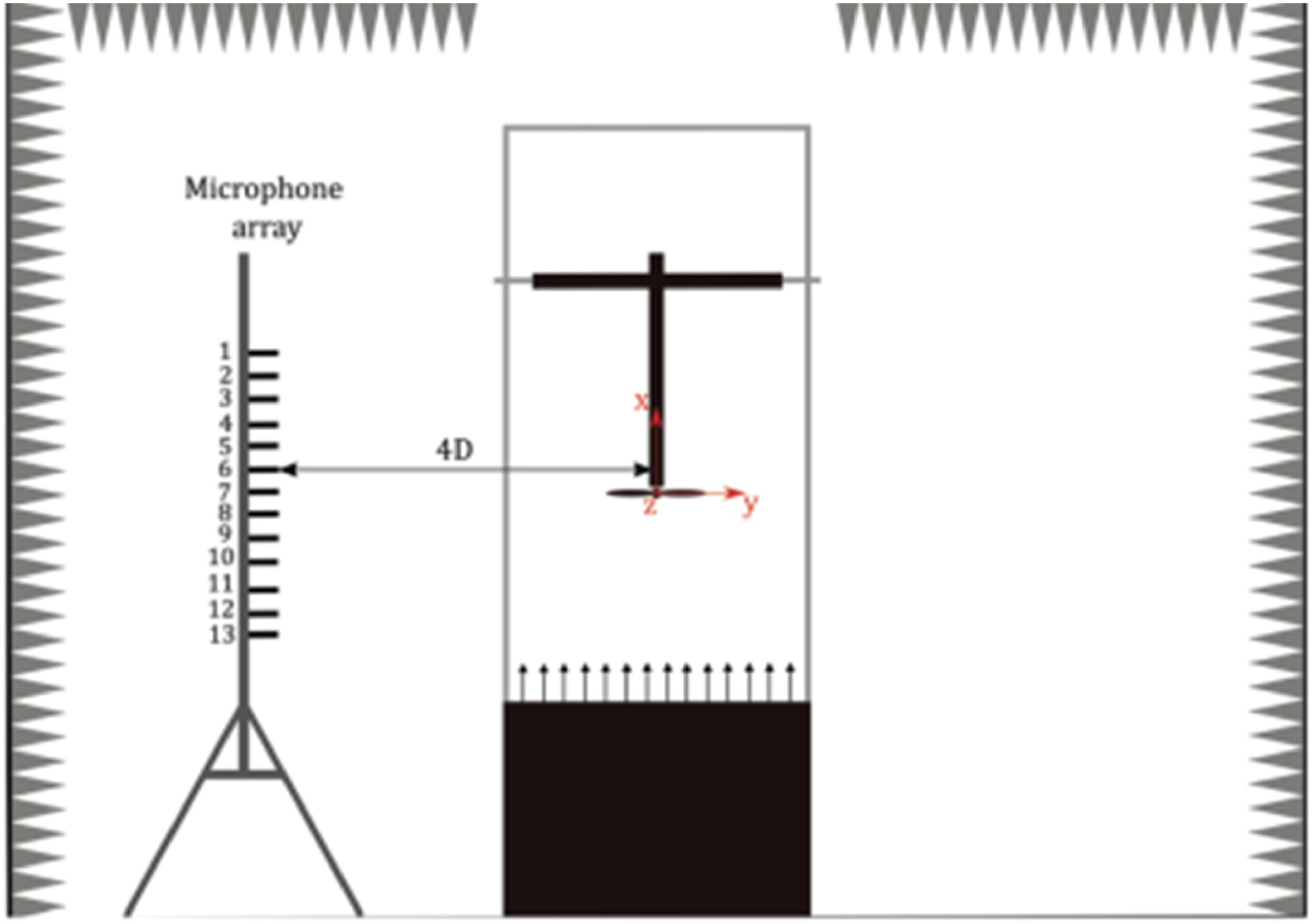

For performance validation, two key parameters were analyzed: the coefficient of thrust 

Formulation comparison
In this section, the propeller geometry from the study by Casalino et al.
11
is used to compare results from DNC with those from the steady-state method. This comparison aims to clarify the differences between Formulation-1A and Formulation-1C, as well as to highlight the limitations of Formulation-1A. For the transient analysis, the HiSA solver in OpenFOAM, using a RANS turbulence model, was employed. A timestep of Receiver locations relative to the propeller used for the comparison study.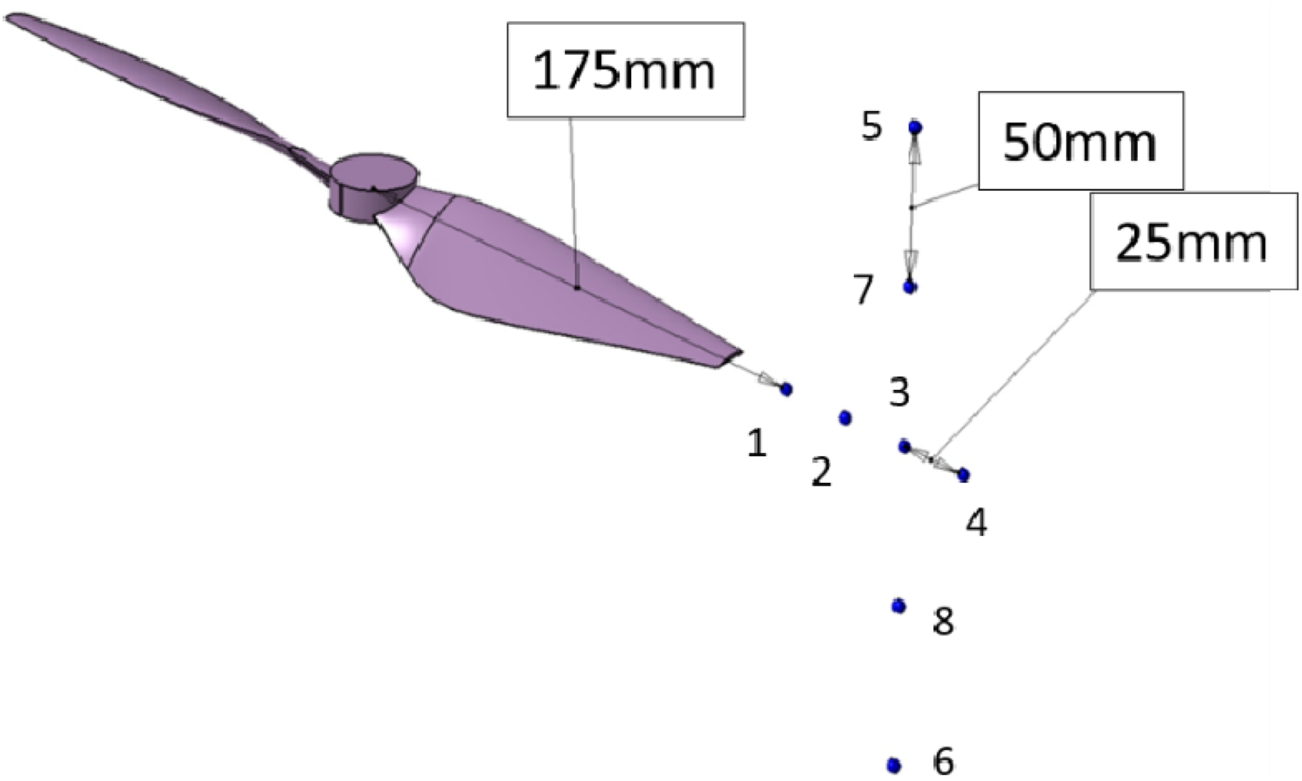
Analysis of Figure 15 reveals that Formulation-1C achieves minimal error when compared with direct noise results, while Formulation-1A shows significant discrepancies. The figure displays pressure time histories for two in-plane receivers (2 and 3) and one out-of-plane receiver (8). For receiver 2 (Figure 15(a)), both direct results and Formulation-1C exhibit pressure variations of approximately 10 Pa, while Formulation-1A shows fluctuations of 50 Pa. As distance increases (Figure 15(b)), Formulation-1A’s pressure range decreases substantially, though residual errors persist. For the out-of-plane receiver (Figure 15(c)), both formulations demonstrate minimal error and yield accurate predictions. These results demonstrate that pressure prediction errors for Formulation-1A peak within the propeller plane. This trend is clearly visible in Figure 16(a) (maximum SPL vs Pressure versus time at Variation of maximum sound pressure level (Max SPL) with respect to (a) x-location and (b) z-location. (): Formulation-1C; ( ): Formulation-1A; (
 ): Direct results.): Formulation-1C; (): Formulation-1A; (): Direct results.
Conclusion
This study establishes a framework for tonal noise prediction of propeller by FWH formulations (both 1A and 1C) with steady-state CFD. Through verification against analytical and validation with numerical, and experimental benchmarks, the approach demonstrates reasonable accuracy for acoustic sources and complex propeller configurations. The implementation within the libAcoustics library for OpenFOAM ensures computational efficiency and parallelization, making the methodology accessible for both academic and industrial applications.
The comparative analysis underscores the superiority of Formulation-1C over Formulation-1A, especially in scenarios involving significant ambient flow, where Formulation-1A’s neglect of convective effects leads to notable discrepancies. By leveraging a steady-state RANS model with a single rotating frame (SRF), the methodology offers substantial computational savings while reliably capturing tonal noise components. However, it is important to note that this approach is inherently limited in its ability to resolve highly transient phenomena such as blade-vortex interaction and cavitation noise, which require high-fidelity unsteady simulations for accurate prediction.
In general, the developed framework provides a practical and efficient tool for propeller noise analysis and optimization. Its successful validation across a range of propeller types and operating conditions demonstrates its potential to support the design and certification of next-generation low-noise propulsion systems. Future work may focus on extending the methodology to address broadband and transient noise mechanisms and its integration with the optimization framework, further enhancing its applicability to the evolving demands of aircraft noise prediction and mitigation. Although the present work focuses on tonal noise, approximate broadband estimates may be obtained using semi-empirical WPS models, such as Schlinker et al. 46 and Goody 47 which can complement steady-state SRF predictions.
Footnotes
Author’s note
First author’s current affiliation: Adelaide University, Adelaide, SA 5005, Australia. The research was conducted while the author was with Turkish Aerospace Industries, Ankara, Turkey. Updated email address:

Funding
The authors received no financial support for the research, authorship, and/or publication of this article.
Declaration of conflicting interests
The authors declared no potential conflicts of interest with respect to the research, authorship, and/or publication of this article.