



Abstract
Additive manufacturing is evolving toward more sophisticated territory for architects and designers, mainly through the increased use of scripting tools. Recognizing this, we present a design and fabrication pipeline comprised of a class of techniques for fabrication and methods of design through discrete computational models. These support a process responsive to varied design intents: this structured workflow expands the design and fabrication space of any input shape, without having to explicitly deal with the complexity of discrete models beforehand. We discuss a multi-resolution-based methodology that incorporates discrete computational methods, spatial additive manufacturing with both robotic and commercial three-dimensional printers, as well as, a free-oriented technique. Finally, we explore the impact of computational power on design outcome, examining in-depth the concept of resolution as a design driver.
Keywords
Introduction
Additive manufacturing (AM) is constantly evolving to offer increased sophistication of outputs and in applications for architects and designers, mainly owing to the use and adaptability of scripting tools. Computer-aided design and manufacturing practices have significantly transformed the way architects design and build. Architects have started to embrace AM technology in their projects, both at the prototype and built scales. In this, architecture remains anchored to a fundamental design process, namely, the manipulation of geometry. It is such geometrical manipulations in conjunction with AM that are of interest in this article. Specifically, this article provides a generalization of an informed alternative to current black-box end-to-end AM pipelines, namely, a multi-resolution-based methodology supported by discrete methods (DMs).
This article presents a structured workflow, comprised of four layers, see Figure 1. The input to the workflow is a raw global shape that will be processed through the workflow’s layers until it is transformed into a discrete shape with multiple resolutions. This allows different resolutions respond to specific design intents such as “the middle part of the shape should be more porous.” The first layer of this workflow discretizes the global input into a voxel-like structure at a default voxel size. The second and third layers select a printing technique and a manufacturing machine, respectively. The fourth layer is the most significant, as it is the one in which the multi-resolution method is applied. Responding to the design intent above, we can select the middle area of the global shape and decrease its resolution (for example, by increasing the size of the grid and/or choosing a less-dense geometry type for this cell). The result of this process is an informed and tailored geometry and fabrication file of raw input.
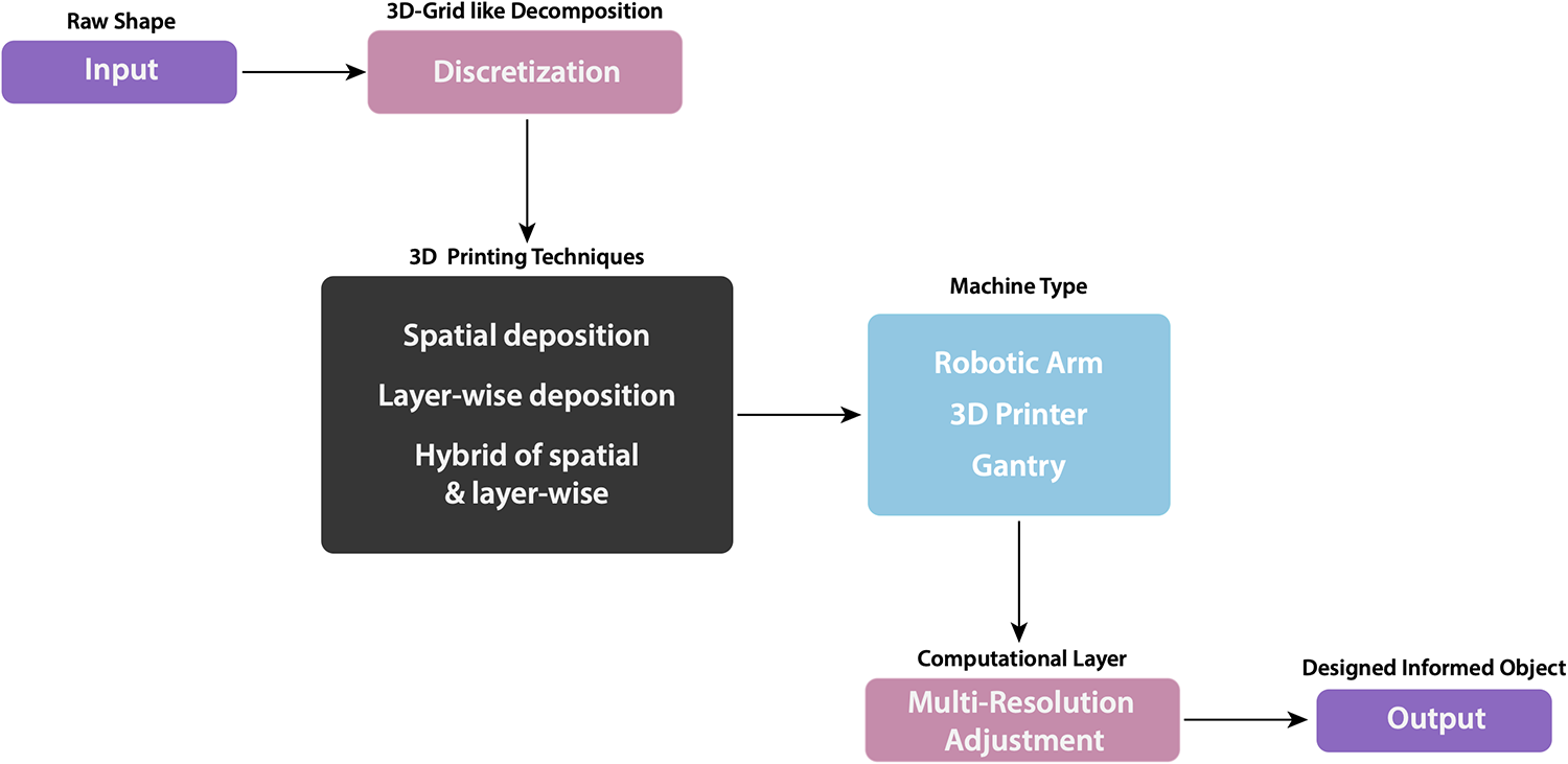
Proposed pipeline based on the multi-resolution method.
This workflow is considered in the context of fused deposition (FD), a subfield of AM, and from a computational analysis perspective. To support this, we will first review computational methods that are based on discrete models. Two main spatial printing techniques are considered, which test fabricating forms at differing scales, and are modeled with different parameters. Finally, we discuss specific fabrication techniques that are supported by our multi-resolution approach. By applying these techniques and methods to infills of closed objects, we demonstrate that this approach can converge to optimal FD solutions.
Background
AM–FD
AM consists of progressive adding of layers of material through numerical control to build a structure to create a global shape. This process of materializing a given form by placing matter where there was not before is fundamentally different from forming and subtracting processes.
AM is ideal for prototyping, namely, the manufacturing of complex topologies which are otherwise too expensive or near impossible to achieve with traditional manufacturing methods. Specific to FD, the fabrication of complex topologies such as overhangs is achieved by the use of supporting material. Although AM can present significant challenges for implementation at the architectural scale, current advances in large-scale AM demonstrate viability of application in building construction regardless of complexity, with more accuracy, faster, and at lower cost than traditional methods. 1 Recent trends have registered that digitization, advanced automation, and new technologies and materials are beginning to affect the construction industry. 2,3 Nonetheless, it is critical to develop efficient techniques and computational methods tailored for architectural scale applications, in order to implement AM in the building industry 4 and to harness the potential augment in productivity that is seen in other industries. 5
Standard three-dimensional (3D) printing process distinguishes two major parts: the outer perimeter or boundary of the object, and the interior of the object or infill. Recent efforts focus on topological optimization of the global shape. Parameters of both, the outer layer and infill, can be modified within the STL generator software. Commercially available slicing software includes undifferentiated 3D infills, interesting for their better mechanical properties as compared to continuous vertical extrusion of patterns in two-dimensional (2D) solutions. Newer developments in slicing software include variations in density and the possibility of manually introducing infill density differentiation by varying the percentage of solid and empty parts within volumetric thresholds defined by the solid meshes interior to the global geometry. However, although one can choose between a limited set of options, the deposition process itself is not considered as part of the design process. 6 Customizing the deposition process 7,8 allows the design criteria to be implemented at a material performance level 9 further enabling control over geometry.
Studies of large-scale production of structural components in architecture indicate that competitive time for fabrication and correct simulation of anisotropic mechanical properties are among the main challenges for future development of the manufacturing process. 1,10 This research studies the digital design itself, prior to the manufacturing process, to further optimize material distribution and robotic tool-path production, potentially increasing the performance and reducing the time required for production of the processed components, as the principal area of opportunity for significant improvement.
The capacity to structure the matrix of indices that define the internal constituents of a form harnesses the potential of informing the AM deposition process with a locally differentiated digital characterization, enabling direct incorporation of performance, simulation, and feedback loop results into the manufacture of form at the material level. 11,12
Current research is widely focused on optimizing mechanical performance, such as in stress-informed AM fabrication techniques. 13 A digital form is specifically tailored for a given application, thereby increasing its opportunity for optimization and reducing material waste. However, robust computational methods specific to AM techniques at a meso- to large-scale are not limited to optimization and engineering roles. The focus of this research builds on current computational methods and fabrication techniques for the manufacture of functional graded form, 14 founded in a performative and aesthetic inquiry of form design and materialization.
Discrete computational methods and resolution
DMs refer to any family of numerical methods that are based on discrete, finite elements. A discrete model can be indexed and serialized, which allows for, in general, fast and independent identification, access, and manipulation of each of its discrete components. In architectural design, DMs are relatively new and are natural consequences of embracing computation. 15 DM are essential for analytical frameworks; for example, in structural design software, where calculations are mostly done using finite-element method (FEM). In design theory, until recently, DMs have been seen in opposition to a style of seamless continuity, say, as exhibited by Foreign Office Architects’ Yokohama International Port Terminal, an early seminal example of the first digital turn. As Carpo 15 suggests in The Second digital Turn, discrete models began to play a more significant role in conventional design processes when AM was thoroughly embraced by architects and designers. From a computational perspective, AM represents a set of indexed coordinates, each individually designed, calculated, and concatenated within a linear structure. This atomistic nature of 3D printing is suggestive of a change in which we think of design as a set of discrete elements that conforms a continuous shape.
In practice, DM break down an object into smaller individual units, yet forming part of an integrative process. There are common uses of discrete computational models in various disciplines, for instance, terrain representation and simulation in the game industry, volumetric imaging in medicine, or granular flows and rock mechanics in engineering. In computer graphics, the synthesis of objects represented by volume elements (voxels), termed voxelization, is the process of approximating geometrically continuous objects with a set of discrete elements.
A key concept in this article is the notion of resolution as a computational strategy that drives a design methodology based on DM. Resolution is normally defined as the amount of data in a given region. 16 In other fields, this concept is fundamental—for instance, digital images measure resolution by its number of pixels, each containing a tuple of numbers that represent values for different channels, alpha, red, green, and blue in a colored image. There are recent examples in architectural research either involving the word “resolution,” or using discrete computational methods, as the main design scheme. For instance, Dillenburger and Hansmeyer 17 were among the first to employ resolution as a driver for architectural expression for their Digital Grotesque and Grotto Prototypes, described as a manifestation of exuberance and a celebration of computational power. Examples which do not employ resolution as a main design driver but exemplify DMs include: Manuel Jiménez Garcia and Gilles Retsin, who in Curvoxels and Voxel Chair, 8,18 use DMs to directly design for 3D spatial printing fabrication; the Computational Chair Design by Phillipe Morel of EZCT Architecture and Design who uses a finite-element analysis (FEA) framework as the design tool; and Cloud Pergola, the Croatian National Pavilion at the Venice Biennale, by Andrasek 19 is an example of large-scale robotic spatial printing, designed through active discrete elements that follow rules. These are all extraordinary examples of design by DM, showcasing a high performance at structural, material wastage or aesthetic capacities.
Approach and methodology
In this article, we describe a design methodology based on discrete elements whose main engine is the concept of multi-resolution. Here, resolution is defined as the quantity of information at a localized region of a discretized 3D shape. In this methodology, we manipulate data rather than geometry, which serves only for visualization purposes. See Figure 2, which illustrates a portion of an ulna bone at various resolutions that has been constituted, programmed, and discretized.

Portion of ulna bone modeled using four resolutions.
The resolution-based methodology is necessarily driven by scripted manipulation of data. These data are structured in a dictionary, which organizes the AM process of shape and infill engineering. The shared discrete language, of both the data structure and its equivalent custom AM code, facilitates local differentiation of the spatial deposition tool paths that results in data-informed material composition. The research described in this article is coded with connections to FEA tools and to modeling software for visualization purposes.
To evaluate the potential of this method, we consider two cases of spatial printing at different scales, using distinct machinery. Both fabrication techniques require particular models on specific parameters, as shown in Table 1.
Fabrication techniques.

FOAM: free-oriented additive manufacturing; SFD: spatial fused deposition; FEA: finite-element analysis; KNN: K-nearest neighbor; DoF: degrees of freedom.
The contribution of this article is to strategically identify and situate a multi-resolution design methodology in the computational layer of the proposed pipeline shown in Figure 1. In doing so, it expands the design and fabrication space of any input shape, without having to explicitly deal with the complexity of discrete models beforehand. We automate this process informed by the parameters shown in Table 1.
Spatial AM in robotic arm and commercial 3D printers
The fabrication technique described in this section builds upon previously published research. Spatial fused deposition (SFD) is a technique in which molten thermoplastic gets extruded and vitrified in space almost instantaneously so a network of threads can be arranged in different self-supporting configurations, generally, responding to either lattice or cellular typologies. The difference with conventional printing techniques resides in the violation of the layer-by-layer deposition principle that AM commonly uses. SFD has demonstrated the potential of optimized functional products, 20 reduced fabrication time for rapid prototyping, 7 and capability of being applied at any orientation without the misgiving of potential deformations due to gravitational forces, in a technique that uses a robotic arm, called free-oriented additive manufacturing (FOAM). 9 This last feature is due to the lightweight properties of thermoplastics, and it is driven by an algorithm that adjusts the printing parameters to any given orientation (Figure 3).
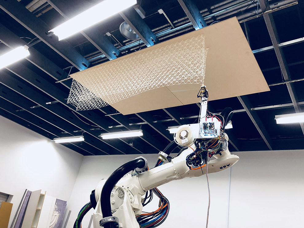
FOAM technique on ABB 6640.
Spatial AM is differentiated into four stages: horizontal, upward, downward, and dangling. 20 The main factors involved in this process are deposition speed, extrusion flow, cooling systems, and collisions check. Spatial 3D printing does not rely singularly on the use of a robotic arm. Instead, 3D printers can be altered to produce spatially printed designs facilitating generalization of this technique. However, programming is essential, as generation of the code file cannot be based solely on using commercial slicing software. Rather, the printing procedure can be organized into different operations: bed extrusion, knot, mid-air, or end of line. This is natural to SFD, since the model is not sliced but rebuilt by following some of the aforementioned typologies.
FOAM technique
FOAM is a robotic fabrication technique intended to print over existing environments without recourse to necessarily printing locking the nozzle vertically and pointing it down onto a horizontal surface. FOAM claims that effort in assembling parts is less necessary, resulting in decreased cost and time in construction.
We developed a cost-effective compact extrusion system that integrates all components at the end-of-the-arm tool (EOAT) as illustrated in Figure 4. A 2.75 mm diameter thermoplastic filament spool is fixed at the EOAT and fed into an MK8 extruder. A variety of thermoplastics were tested, including PLA, PLA+, ABS, ABS+, and PETG. In this research, we used commercial PLA spools, as these presented the best printing results due to its wide range of melting temperature, 190°C–210°C.

Printing end: end-of-arm tool used with the FOAM method. A. ABS nozzle protector. B. M6 threaded barrel hot end. C. Air hose Ø4mm. D. MK8 Nema 17 extruder. E. Ø 2.75mm filament feeder. F. 2″×12″×0.12″ Aluminum buffer plate. G. ATI QC-110 tool plate. H. QC-110 master plate. I. Ø 2.75mm PLA filament spool. J. Electronic box. K. Push-In signal connector.
FOAM benefits from a generous robotic reach, which scales up design opportunities and makes this technique freely and adaptable to reach any point within the robotic work-cell. This makes the printing optimal for flexibility to 3D print on geometrically complex built scenarios. FOAM was tested on a 6-axis 6640 ABB robotic arm sitting on a 6-m length track, proving its viability through different scenarios. The main instance checked the coordination and synchronization of two robotic arms, one holding the printing end, and the second holding a planar surface. The robot holding the surface situated it at different orientations, while the printing robot was able to continue printing the same object, proving successful the technique, since no practical deformation was encountered when changing the orientation (Figure 5).

Dynamic printing setup.
A second configuration tested the viability of this technique at a larger scale, printing a lattice structure hanging from a horizontal surface fixed at the ceiling of the work cell, successfully resulting in a 2 m × 1.5 m piece with no need of assemblage. This is shown in Figure 3.
One of the challenges for robotic spatial printing is to synchronize the robotic motion, stepper motor feed-rate, necessary wait times at points of discontinuity of the print model, and the cooling system that makes this technique possible. An overall of 3 mm/s speed combined with an 1/8 motor step was proven successful. The overall fidelity between the digital and physical models was maintained at a 93% approx., measuring this parameter based on overall deformation, regardless the orientation of the object.
Spatial AM on 3D delta printers
Applying spatial printing on commercial 3D printers is becoming widely popular. It is a cost-effective technique that offers materially efficient rapid prototyping, 7 skipping any hardship that the use of robotic arms might imply. In this research, we used delta-type 3D printers as their motors move more quickly along the Z axis than do Cartesian printers. This section is divided into two main parts, the first relates to hardware adjustments; the second, to software considerations.
Hardware adjustments
Although technically it is not strictly necessary to alter any major component of a 3D printer, there are always adjustments that will yield a variety of improved results. Air cooling is a main factor of spatial printing; therefore, having air-hoses or air-adaptors that point more precisely at the tip of the nozzle is recommended. Hot end and nozzles will have a major impact on print quality. This research uses bespoke nozzles that adjust the printing thickness to the research needs (Figure 6).

Custom nozzle for FD delivery.
The diameter of the aperture of the nozzle directly determines the thickness of the printed extrusion, whereas the morphology of the hot end will constraint the angle at which a lattice or cellular structure can be printed (Figure 7). Thus, the narrower the hot end, the less constrained the print is. This affects precisely the heating source and the thermal sensor. We have tested multiple options, ranging from conventional 12 V ceramic cartridges inserted into an aluminum block to a 22-gauge nichrome wire wrapping an M6 threaded barrel. More sophisticated options such as a bespoke mechanized all-in-one hot end will offer a higher precision and printing quality.
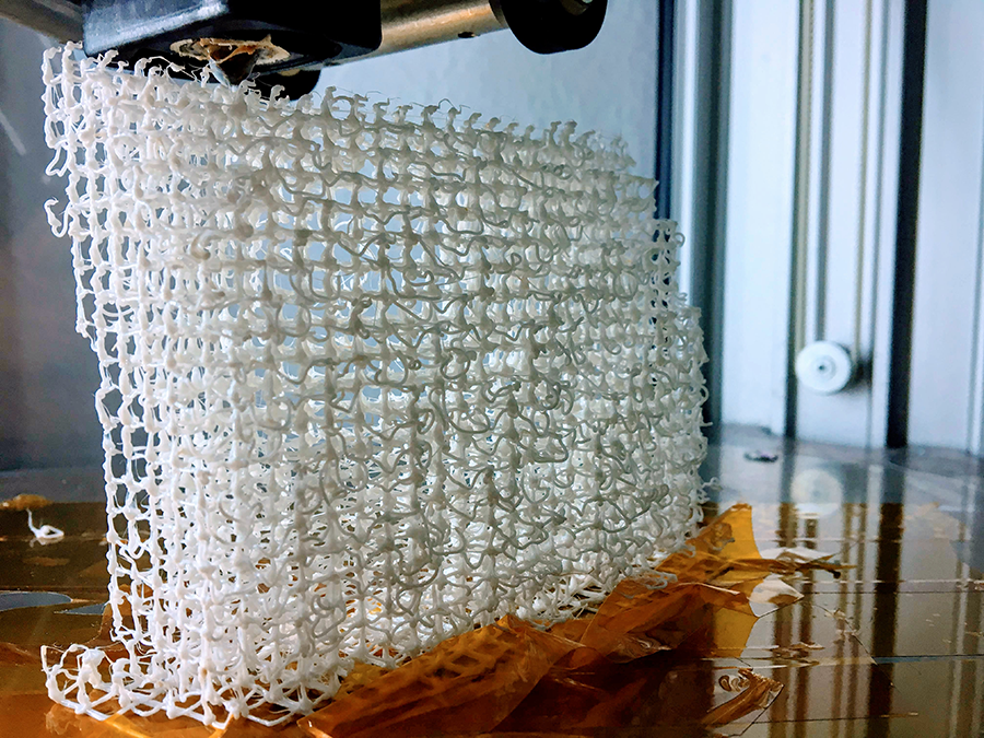
Cellular structure on 3D delta printer.
Software considerations
Commercial 3D printing software cannot be used with this technique. These rely on layer-wise deposition, and SFD violates this constraint. Regardless of which algorithm construes a design typology from object to a suitable print, for the success of this technique, the gCode generator has to convert XYZ coordinates to machine instructions. An algorithm that weaves moving commands, extrusion flow-rate, waiting times at discontinuities, and cooling control is imperative in order to achieve successful results (Figure 8). Due to a highly complex nest of instructions, use of an online viewer software as a bridge between the generated gCode and the fabrication step is recommended to avoid potential damage.
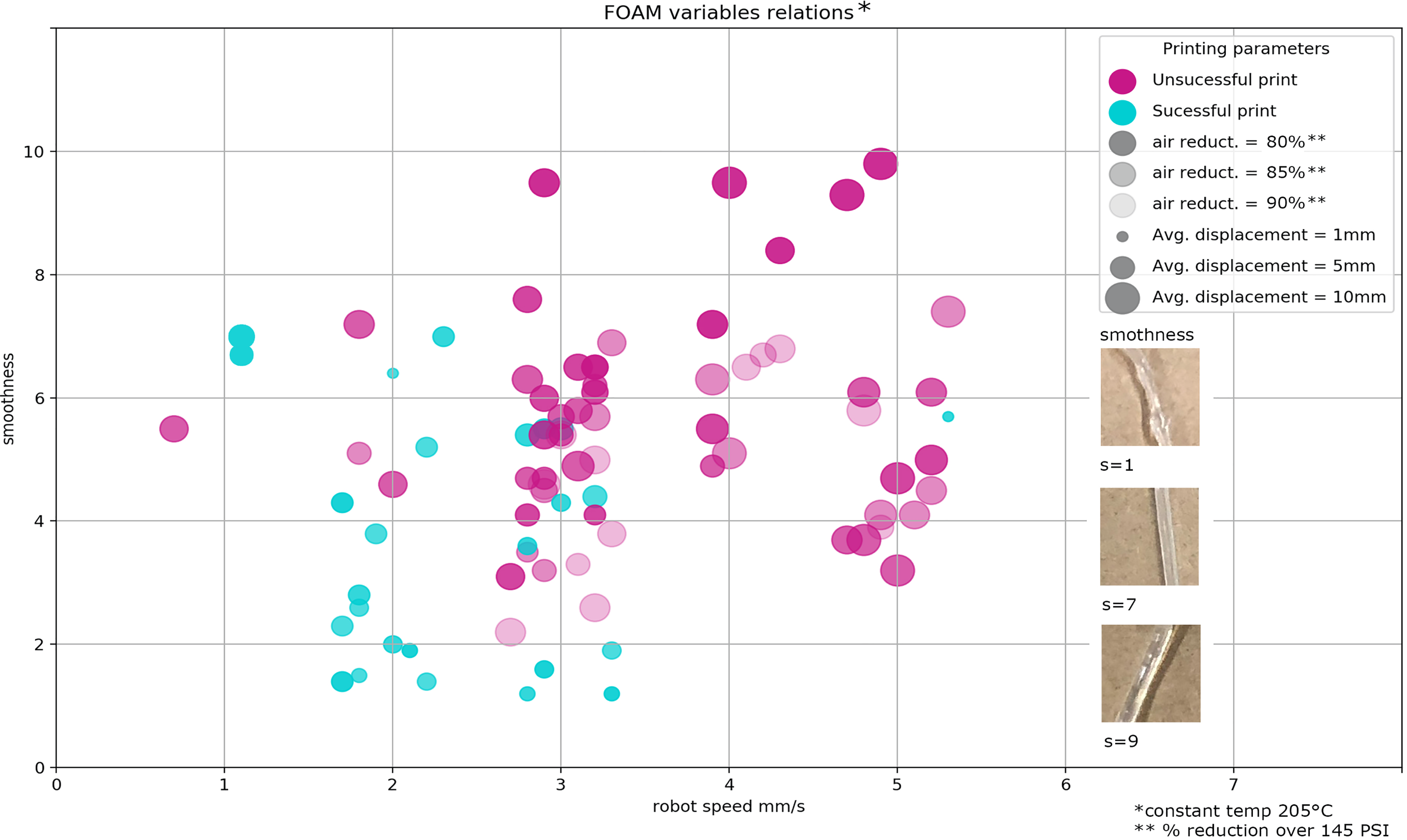
PLA test results.
Printing constraints
SFD processes in robotic applications are best suited to linear segments over curvilinear segments. On the contrary, 3D printers are limited to linear movements. Each point of discontinuity in a given structure presents different wait time scenarios in order to ensure proper bonding with already printed material and to deal with precision at drastic angle changes. Furthermore, flow-rate adjustments are needed to respond to tensile efforts that are caused by the nozzle when moving.
One of the challenges of this technique is to avoid potential collisions with material that has already been printed. Simple strategies are necessary to ensure successful results, such as offsetting the Z coordinates at the last point of each segment or require a more elaborate approach such as applying a backtracking algorithm in the design stage which can calculate whether a collision might occur.
Design computational methods
In this section, we mainly describe two complementary methods. The first, multi-resolution-based modeling, acts as the computational engine for the design and manufacturing process. That is, using this model, we design an object which is accommodated to output specific parameters for different fabrication techniques. The second method hybridizes a multi-resolution approach with a layer-wise approach, resulting in an indexed point cloud object which its infill pattern is modified to achieve optimal material and structural performance.
Multi-resolution-based methodology
The concept of resolution in design has not been highly explored. In the “Discrete Computational Methods and Resolution” section of this article, we reviewed previous work, 8,16,18,19 where even though the term resolution although not explicitly expressed, it is implicit in the use of discrete computational methods (the size of the discrete elements can be measured by resolution). It is only in Dillenburger and Hansmeyer’s study 17 where resolution is described as the main engine of each technique. In Ladron de Guevara et al.’s 16 study, multi-resolution refers to the potential that adjustments in multiple resolutions across a studied object may offer as a design opportunity, since the inherent discreteness of the process provides the means to reconfigure the object’s morphology. An object may embrace multiple configurations at once. These configurations respond to degrees of resolution that correspond to regions of interest. Thus, the more interesting a region, the higher the resolution it presents. The number of different resolutions is determined by certain design criteria. We study and use the multi-resolution concept to create a pipeline that necessarily uses this layer after selecting a printing technique and a manufacturing machine, to expand the design options for any given input shape.
The algorithm has three parts: shape analysis, creation of a 3D grid as the computational structure, and design of discrete elements. This method contributes to the generalization of the use of resolution as a concept for the design of architectural components and uses discrete computational models for its development. However, the authors acknowledge this is just the first of many steps in order for this method to be applicable to the construction industry. This approach has been tested on models of human bones, see Figure 9. This human scale simplifies barriers, allowing us to focus only on the design of the bone, without additional considerations, such as external and environmental agents, which would be included at an architectural scale.

Multi-resolution method in ulna bone.
Computational core
The data are organized into two main object classes.
A 3D grid establishes the multiple resolutions across the object, indexes them, connecting their computational units, called arxels, through a graph data structure, where arxels are the vertices, and edges of the graph are defined by the type of relationship between neighboring arxels.
Arxel—an acronym for architectural element—is a structure that stores the following data: material, local name, geometric typology, resolution type, location, and neighbors. For visualization purposes, arxels are represented by voxels or cuboids and are not until the end of the process, where the voxels are substituted by a final designed unit.
A linear language is chosen as the design typology, responding to the inherently segmental nature of spatial printing, conforming to a nomenclature of numerical matrix configurations, covering a range of possibilities, from simple to more complex shapes, as shown in Figure 10.

Nomenclature of design possibilities.
Infill optimization by FEA models
FEA models can influence 3D printing. Correct simulations of anisotropic mechanical properties are among the challenges for future development of manufacturing processes. FEA models provide a sophisticated alternative to modifying material distribution in fused deposition models (FDMs), contributing to potential improvements in mechanical behavior. Locally controlling filament deposition during FDM by the application of FEA models has shown successful transformation of mechanical properties. 21
Recent developments in slicing software combine variations in infill density differentiation by adjusting the percentage between solid and void parts within volumetric thresholds. By this technique, the resulting infill is computed as an independent set of volumes, which offer real alternatives for design, but fragile mechanical performance due to discontinuous fibers. 22
Differentiated infill method
This approach assesses whether the rationalization of mechanical behavior in graded components is able to enhance and improve structural performance on components manufactured using FD techniques. This research focuses on optimizing mechanical performance along principal stress lines, resulting in a porous cellular object. A method for automating infill differentiation that ensures fiber continuity while varying fiber density informed by FEA models (Figure 11) could potentially improve mechanical properties without recourse to material change.
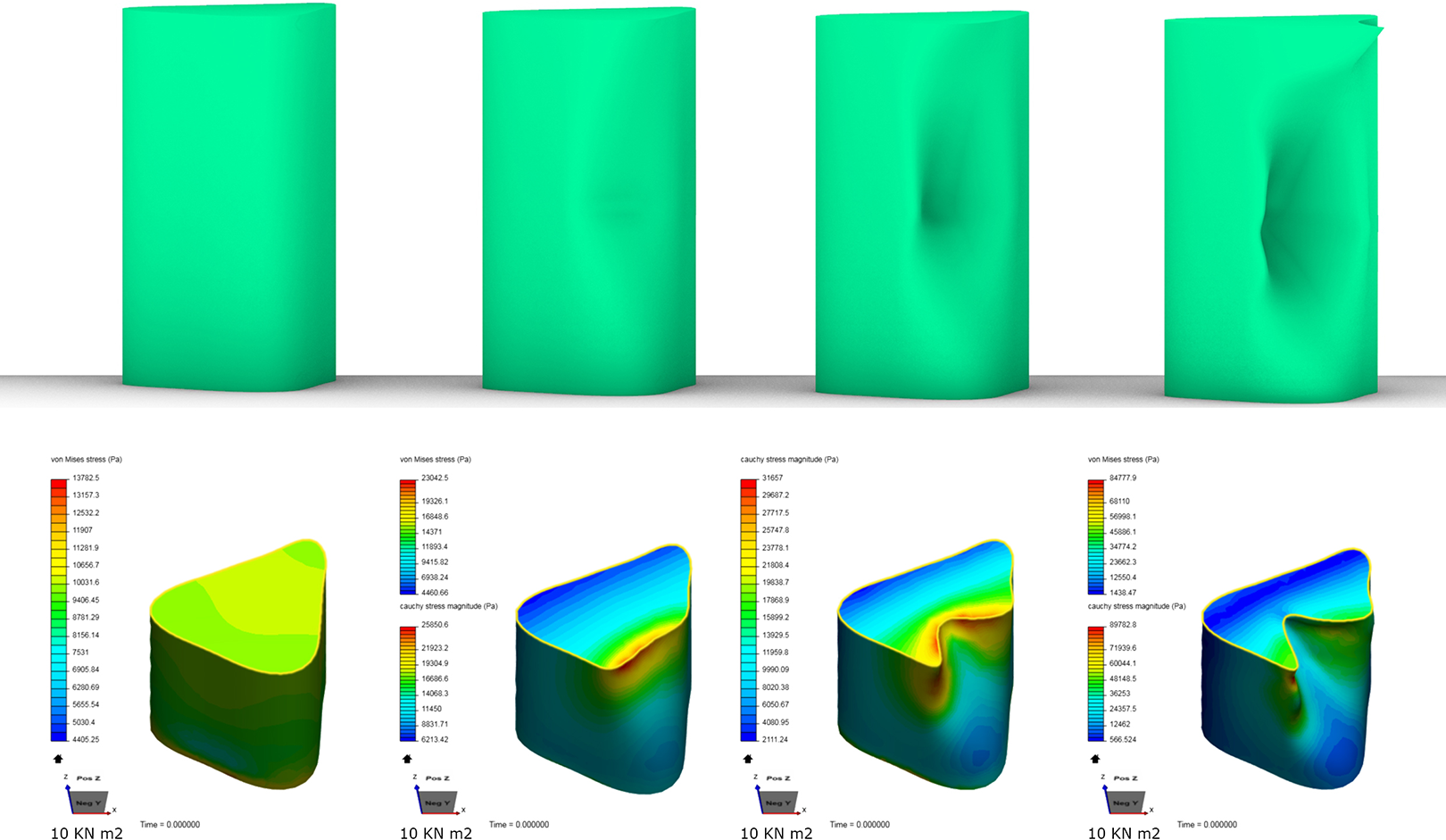
Sequence of denting force application and FEM results.
From FEM to gCode
From a holistic point of view, complex geometries are analyzed under FEA methods and discretized following a multi-resolution approach that respond to certain design criteria. The result of these analyses must inform the design of the piece, yielding to a differentiated infill optimizing the mechanical performance of the piece. This is illustrated in Figure 12. Consequently, FEM follows parallel design inputs, such as aesthetic values or density variation. An object is first imported to SimScale cloud-based FEM for discretization analyses. The data are then exported to ParaView, which acts as a bridge between SimScale and Rhinoceros®, exporting geometrical analyzed samples as 3D points, that Rhinoceros can read, and stress values in the form of a CSV file. An algorithm links both, geometrical 3D points with their respective stress values, indexes and structures this information, and creates a new infill that ultimately will be exported as gCode commands.
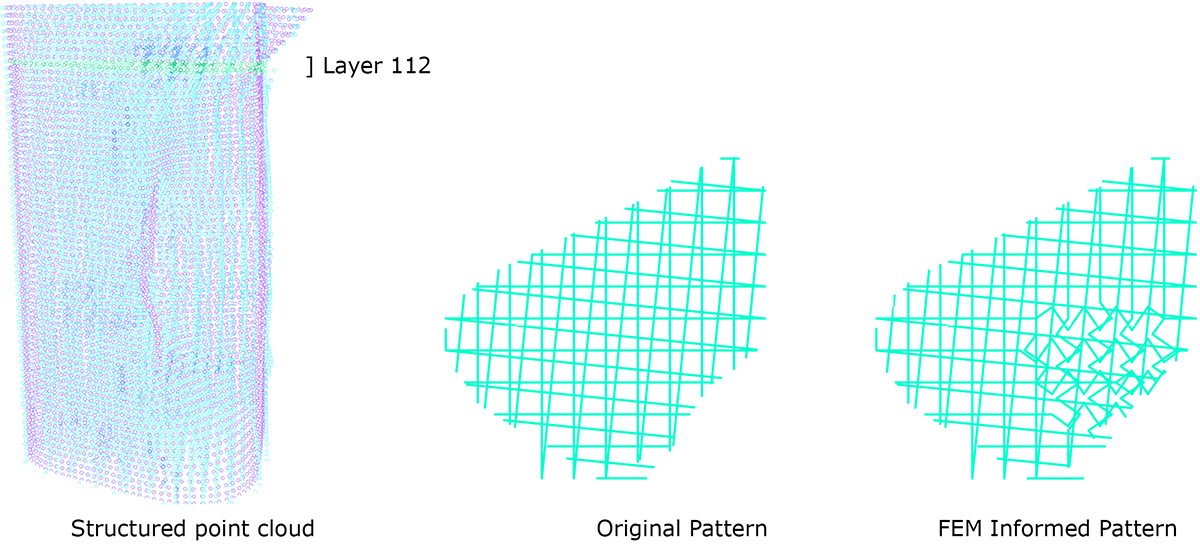
Custom infill design informed by FEA models.
Discussion
Design and fabrication processes that involve standard 3D printing do not present major challenges for designers because of the ease of black-box tool-pathing software. Although these accessible solutions are active contributors to the embracement of new technology, we believe that intervening in both the tool-path stage (that bridges design and fabrication) and the generation of an utterly customized object, constitute an alternative and flexible pipeline that expands the design space.
Current computational power makes possible to think of and design objects that combine multiple resolutions. Approximating form with discrete units of variable levels of resolution allows the designer to work at the level of the constituent element, expanding the design opportunities but requiring the atomistic understanding of a continuous form as an informed addition of units and capacities. The indexing, structuring, and geometrical definition of 3D printable informed units requires the designer to work with data as abstract equivalents of geometry and process of fabrication at the same time.
This method offers a way to highly customize the form and fabrication of an object, adding more parameters to tune during the design process. The more common parametric design pipelines comprise: (1) the tuning of certain decided parameters in a parametric design software such as Grasshopper or Dynamo; (2) baking a decided instance; (3) saving the file as .STL and sending it to a tool-pathing software, prior to (4) 3D print. We start, instead, by adding the number and type of resolutions to the object parameters in step (1). We then create a second layer of parametric decisions between steps (2) and (4), substituting step (3), all within one environment. This second layer of decisions is data driven. We believe that understanding the object as a set of ordered containers of parametrizable information that directly inform the overall shape and later fabrication could present a potential to augment the design space, in a manner similar to the way parametric design software provide augmentation in the decision-making stage.
Future work
This research contributes to the generalization of the use of resolution as a concept for the design of architectural components and uses discrete computational models for its development. However, the authors acknowledge this is just the first of many steps in order for this method to be applicable to the construction industry.
Even though the flexibility of the FOAM pipeline contributes to the generalization of structured computationally driven workflows, this is only an initial step that tests a limited number of techniques and computational strategies. Further research is needed in order to tackle the main issues of FD models such as structural feasibility or scalability. In addition, alternative permutations, modifications, and combinations of the techniques presented in this article might result in research that contributes further to the advancement in AM. We believe that inserting the data manipulation section between the tool and output layers augments the flexibility in the design output, leveraging informed designs and offering different platforms of inquiry.
Conclusion
This article proposes a new pipeline based on multi-resolution within a DMs approach (see Figure 13). This pipeline has been discussed in terms of the state-of-the-art in resolution-related design schemes. The pipeline is composed of three main layers: fabrication techniques, tools, and a set of computational design objectives. Each layer is potentially expandable. We have explored several workflows that result from particular combinations of these nodes.
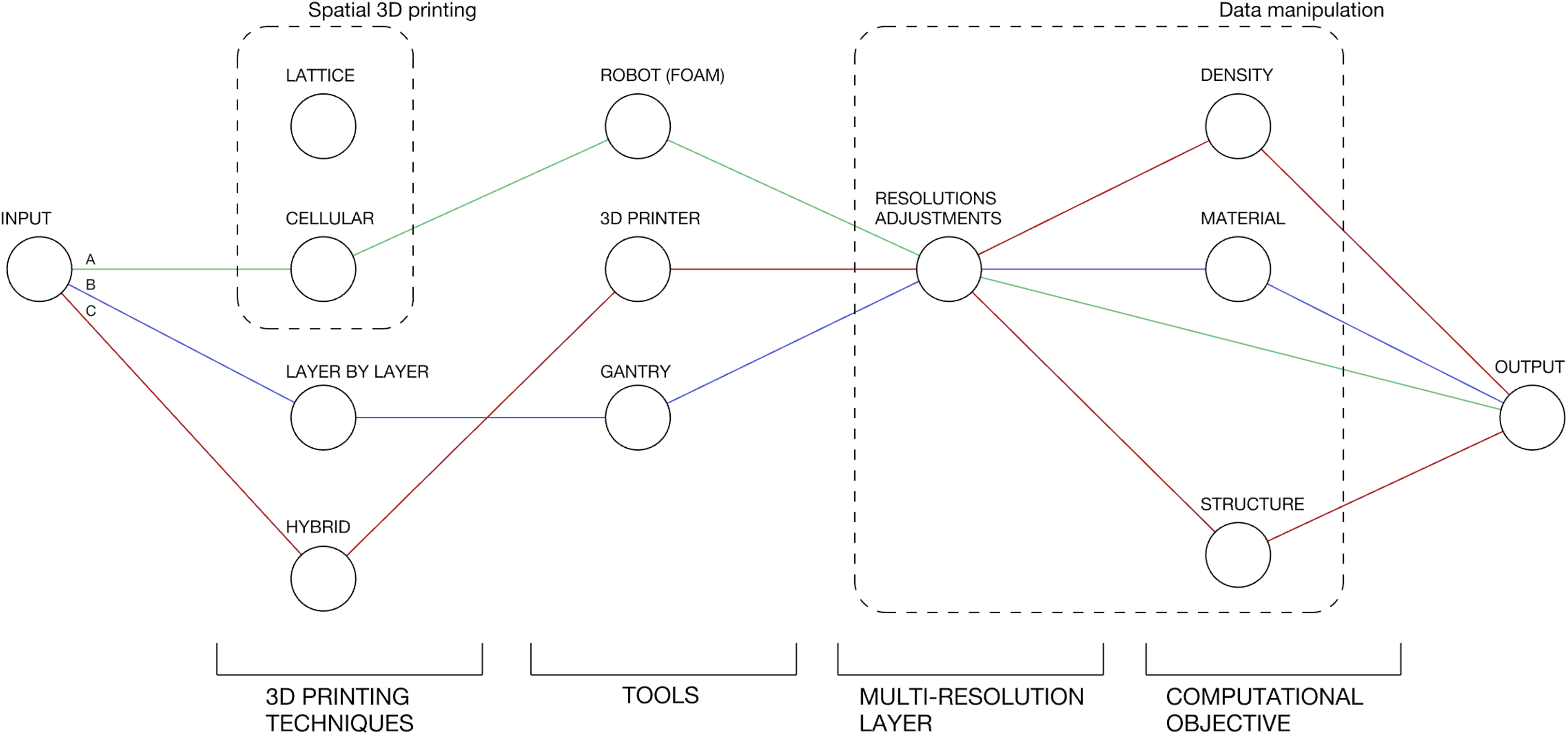
Multi-resolution pipeline.
The pipeline has been tested with three printing techniques: The first, FOAM, employs a robotic arm but does not need a planar horizontal surface upon which to deposit material. This technique has proven to be successful in printing onto situated built surfaces regardless their orientation, achieving a large scale without the need of assembly. The second, SFD, on delta 3D printers presents successful results for rapid prototyping and for fully finished products at a 3D printer scale. The last technique is a hybrid between spatial printing and layer-wise deposition, operating at a higher level of resolution on the indices that present weak values in the FEM analysis.
The main outcomes of this article are: Divergent design drivers were tested applying SFD models as well as FEA, informing custom infills using layer-by-layer deposition. To consider these factors, we have described AM from a computational point of view, with a special attention to FD. We have tested SFD at different scales using specific machines. We have conducted an analysis of the main engine of our proposed pipeline, based on multi-resolution adjustments. Finally, we demonstrate potential convergence to a computational approach based on FEA, for optimized differentiated infills of thermoplastic components.
Footnotes
Declaration of conflicting interests
The author(s) declared no potential conflicts of interest with respect to the research, authorship, and/or publication of this article.
Funding
The author(s) received no financial support for the research, authorship, and/or publication of this article.
