
Abstract
In this paper, we argue that synthetic biology can help us employ living systems’ unique capacity for self-construction and biomaterial production toward developing novel architectural fabrication paradigms, in which both the raw material production and its refinement into a target structure can be merged into a single computational process embedded in the living structure itself. To demonstrate, here we introduce bioPheme, a novel biofabrication method for engineering bacteria to build biomaterial(s) of designer’s choice into arbitrary 2D geometries specified via transient UV tracing. To this end, we present the design, construction, and testing of the enabling synthetic DNA circuit, which, once inserted into a bacterial colony, allows the bacteria to execute spatial computation by interacting with one another based on the if-then rules encoded in this circuit. At the heart of this genetic circuit is a pair of UV sensor – actuator, and a pair of cell-to-cell signal transmitter – receptor modules, created with genes extracted from the virus λ Phage and marine bacterium Vibrio fischeri, respectively. These modules are wired together to help designers engineer bacteria to build macro-scale structures with seamlessly integrated biomaterials, thereby bridge the molecular and architectural scales. In this way, a bacterial lawn can be programmed to produce different objects with complementary biomaterial compositions, such as a biomineralized superstructure and an elastic tissue filling in-between. In summary, this paper focuses on how scientists’ increasing ability to harness the innate computational capacity of living cells can help designers create self-constructing structures for architectural biofabrication. Through the discussions in this paper, we aim to initiate a shift in today’s biodesign practices toward a greater appreciation and adoption of bottom-up governance of living structures. We are confident that such a paradigm shift will allow for more efficient and sustainable biofabrication systems in the 4th industrial revolution and beyond.
Keywords
Introduction
All multicellular structures in nature, whether embryos or trees, involve fascinating computational processes through which their constituent cells interact with one another and collectively build these diverse “living architectures” (Figure 1). In this process, cells constantly monitor their local environment for chemical, mechanical, electrical, and optical cues to translate this incoming information into various spatial actions; such as initiating cytoskeletal movements for shape-shifting, or producing membrane-bound proteins for adhesion-mediated migration, or even transmitting various cell-to-cell signaling molecules for communicating with the neighboring cells.1,2 Spatial interactions like these enable individual cells to build larger tissue and organ hierarchies, giving rise to self-constructing complex biological architectures we see in and around us.3,4

Examples for multicellular biological structures’ ability to self-construct into diverse shapes and forms through the process of morphogenesis. Clockwise from upper left panel: leaves of African Acacia, developing mouse embryo, fungi Clathrus ruber, and squid Sepioloidea lineolata. The embryo micrograph is courtesy of S. Shankar, University of Oxford, UK.
This capacity of biological cells to process complex environmental stimuli into logical spatial organization is facilitated by a series of if-then rules physically encoded in their genomes. 5 These rules enable biological cells to actuate a series of information-triggered bodily responses such as synchronous migration, differential proliferation, collective folding, chemotactic locomotion, adhesion, sorting, fusion, material secretion, and so on. 2 By coupling these acts of physical computation to their unique capacity to self-replicate, biological cells carry out the complex mechanics of morphogenetic development and thereby give rise to the most critical hallmark of living biological structures: self-construction.
The phenomenon of self-construction in biological structures and its computational nature—evidenced by these rule-based morphogenetic acts of building—begs the question: Can we edit these rules of interaction embodied in the constituent cells, and thereby conceive of multicellular structures as a design medium? This question has been central to the inquiry of synthetic morphogenesis, a newly emerging branch of synthetic biology, that is concerned with creating high-level patterns in multicellular systems by manipulating the “rules” of lower level interactions between constituent cells.6,7 The methodology of synthetic biology involves introducing these novel rules as encoded in synthetic genetic regulatory networks, or “DNA circuits,” into a cell for it to then decode and execute these novel rules.8–14 Progress in this field has so far demonstrated the expansive power of synthetic biology to harness nature as a design medium and steer its morphogenetic processes toward designed ends.15–22 Can this approach be scaled up to the field of architectural fabrication?
Although synthetic biology has not yet been utilized to address problems of architecture, recently there has been a marked interest in biology among artists, architects, and product designers23–26 Furthermore, there have been several concrete examples demonstrating how biological organisms’ innate capacity for biomaterial production can be employed in design practices, creating opportunities to apply the theory and methodology of synthetic biology in the future. Some notable examples include bricks made by exploiting the natural ability of bacterium Sporosarcina pasteurii to turn calcium chloride into calcium carbonate, 27 furniture by employing the innate tendency of fungal mycelium to reinforce network-like structures, 28 and textiles by harvesting the intrinsic capacity of bacterium Acetobacter xylinum to create cellulose biofilm in liquid environments. 29 In these examples, fine tuning of material properties is made through changing the growth and incubation conditions, while control over the final form is achieved through external form-giving equipment such as molds, or 3D printers. In other words, as demonstrated by these state-of-the art examples, designers have so far been exploiting mostly the raw material production capacity of biological matter and have yet to tap into harnessing its capacity for computational self-construction.
In a way, this current state of architectural biofabrication is akin to the early days of aviation when humans could easily make an object fly by simply attaching wings to it; yet, they had no control over the direction in which the object flew, or when and where it landed. Similarly, today we can easily get a biomaterial substance to grow; but we cannot assign from within the direction in which it should grow, or when it should stop growing. Early aviators solved this direction control problem by steering the wings through a built-in sensing and actuation mechanism, as well as by developing a language that enabled the human designer to directly communicate with this built-in machinery. 30 This way, humanity has advanced from aimlessly flying winged objects into self-steering planes with cybernetic autopilots.
Similarly, to reach the next level in biofabrication, it will be critical for designers to embrace an analogous approach—except that biological cells already have built-in sensing and actuation mechanisms, as well as a “language” in-place via which these mechanisms operate. 5 If we can use this language to harness the self-organizational capacity of biological matter to not only grow the raw biomaterial, but also to have this biomaterial build itself into our desired target form, we can then overcome architectural biofabrication’s current dependence on external shape-giving equipment, as well as its resulting drawbacks like the difficulty of sustainable mass-fabrication. Therefore, in this paper we argue that architecture in the Fourth Industrial Revolution must focus on innovating novel biofabrication methods that are specifically tailored to making the most of the computational form creation capacity of biological matter, instead of merely appropriating existing fabrication methods that humans happened to develop for innate substances like plastics that are incapable of self-construction in the first place.
In order to illustrate one instance of this goal, here we introduce bioPheme: a novel biofabrication method in which much of the construction process unfolds in a bottom-up fashion, mediated through cell-to-cells interactions by design. Rules for these interactions are encoded in a synthetic genetic circuit made of DNA (Figure 2), and inserted into the host cells, which in this case are bacterial cells (Escherichia coli JM2.300 strain). An initial transient top-down input of ultraviolet (UV) stimulus prompts bacteria to turn this synthetic circuit on and execute the encoded if-then rules.

Abstract schema of the synthetic genetic circuit made of DNA, encoding rules of interaction by design.
Accordingly, in bioPheme, fabrication process starts with the designer tracing their desired target geometry into a “bacterial lawn” using a UV emitter (Figure 3), which takes in the order of seconds to minutes to deploy. Reception of this UV signal initiates a cascade of actions guided by the if-then rules encoded in the circuit, and results in the engineered bacteria to start manufacturing a 2D sheet made of selected biomaterials into the shape initially traced by the UV beam. In other words, in bioPheme, it is enough for the bacterial lawn to be initially exposed to UV traces for only a couple of seconds; bacteria can then be left alone to autonomously develop the target object into the specified shape.
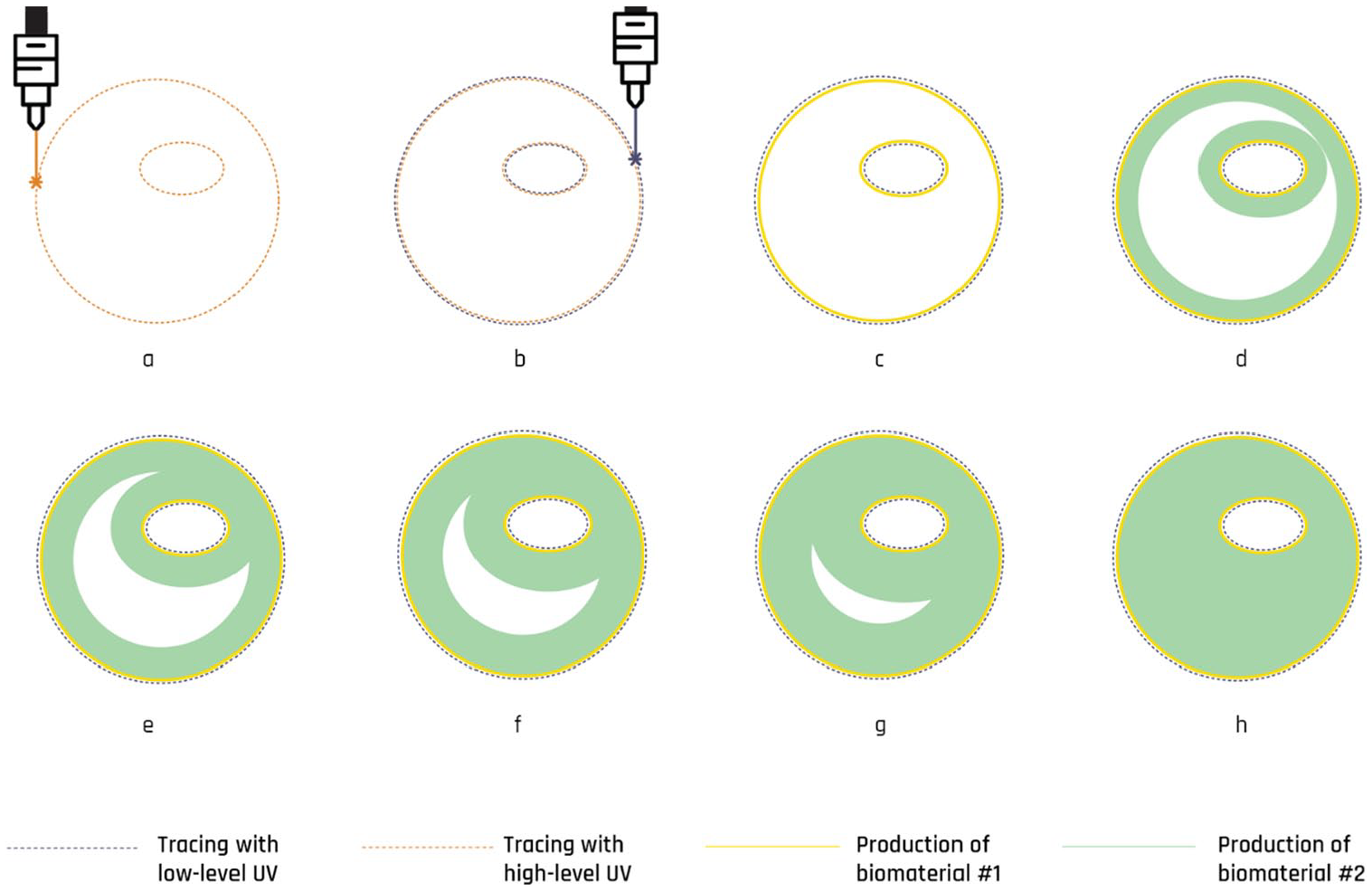
High-level stepwise breakdown of the fabrication workflow in the proposed method. (a) The positive boundaries of the shape are traced with a laser beam at high UV level. Tracing with high UV results in two events: growth of biomaterial#1 at the traces (see step c), as well as initiation of a cell-to-cell communication signal at the traces, which then propagates across the entire lawn and fills in the shape. Reception of this signal prompts the production of biomaterial#2 (see steps d–h). (b) The “negative” boundaries of the shape are traced with a laser beam at low UV level. Low UV tracing acts as a barrier by enabling propagation to stay inside the shape. (h) Final 2D product: circle with an ellipse-shaped hole inside, made of two different biomaterials.
When compared to existing top-down biofabrication methods, of which molding is the most commonplace, it is clear that bioPheme still relies on an external, top-down cue (i.e., the UV tracing) for the specification of the final shape. However, because in bioPheme this top-down cue is as agile as a UV beam, this dependence does not hinder its capacity for sustainable mass fabrication. This is because in bioPheme, UV tracing is not an external aid that must stay with the object throughout the entire fabrication process like a mold; but instead it is a transient environmental input to the computational form-making machinery inserted into the biological cells themselves (i.e., the genetic circuit). In other words, once the final shape is specified via UV tracing, which takes in the order of seconds, rest of the fabrication process can be left to the computational form generation ability of bacterial cells. This independence from external form-giving machinery gives bioPheme an advantage for scaling up not only in size, but also in production capacity, enabling many products to be fabricated in parallel without additional cost. Furthermore, this ability to specify the target shape through UV stimulus also enables designers to create shapes on demand by simply changing the UV tracing pattern, without needing to interfere with the genetic circuit architecture for each new target geometry. Whereas in the molding method, one would need to build a new mold from scratch for each new pattern, further tapering economical mass fabrication. As a result, we argue that using bioPheme, large-scale biofabrication processes can be liberated from the current drawbacks of methods involving external form giving machinery (e.g., molds, 3D printers), and instead architects can begin to leverage biological matter’s innate capacity for self-construction.
BioPheme: Multimaterial bioprinting—minus the printer
This project arose from a recognition that the following questions will be critical for architectural biofabrication: What if we could develop a shape-giving mechanism that does not impose the shape into the living matter externally, but rather directs it from within, via the interactions between constituent cells? Can we implement this mechanism to the cells in a way that it gets replicated as the cells self-replicate? Can we control and tune this mechanism externally in a quick and contactless way? These questions are motivated by the dichotomy between how current biofabrication approaches impose form into living systems in a top-down fashion, versus how living systems already have tremendous internal capacity for creating a diverse set of forms bottom-up.
To tackle this issue, in bioPheme, our aim is to mass-fabricate scalable 2D shapes on-demand, and we achieve this by programming the cell-to-cell interactions between bacteria through a synthetic genetic circuit made of DNA encoding novel rules of interaction by design (Figure 2). A series of if-then rules encoded in this circuit are called upon as bacteria are exposed to different environmental stimuli, such as different levels of UV excitation, or an incoming cell-to-cell communication signal. Through this DNA circuit, we program a “bacterial lawn,” which is a homogeneous single layer of monoclonal engineered bacteria, to respond UV excitation by initiating a synthetic cell-to-cell communication signal. Once bacteria generate this diffusible signal, by the design of this circuit, the signal does not diffuse away and die off; but rather starts to propagate to the rest of the colony, activating other downstream synthetic functions in neighboring bacteria that were not exposed to UV. Details of this process where bacteria communicate with one another and execute local computations per rules encoded in the synthetic genetic circuit is described in detail in Figure 4. Although this approach still relies on an external cue for instructing to the bacterial lawn the desired end shape, as discussed above, this global cue is a mere input to the computational form generation process. Therefore the fabrication process still primarily relies on cells’ capacity to process environmental inputs by executing novel rules of interaction encoded in the inserted synthetic genetic circuits.
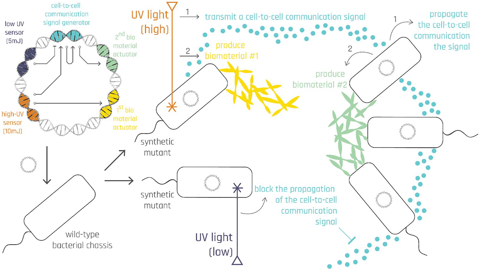
Low-level stepwise breakdown of the fabrication workflow and its inner workings across orders of magnitude: nanometers (DNA circuit), micrometers (bacterial colony), and millimeters/centimeters (UV tracing).
The specific cell-to-cell communication mechanism we used in this project is called Quorum Sensing (QS)4,31,32 and it has been widely used by synthetic biologists for over a decade to program interactions between bacteria to have them self-organize into diverse shapes.15–19,20,22,33 However, so far these shapes have been exclusively on the order of millimeters, which is not immediately applicable to architectural fabrication occurring at the scale of centimeters and meters. It is to bridge this scale gap and enlarge the cell-to-cell communication activity zone that, in bioPheme, we turn to optogenetics 34 : control of gene expression through light input. We merge QS and optogenetics by deploying a light-based cue (of UV) as our external input to the synthetic genetic system, which thereby enable the designer to trace arbitrary target shapes in the scale of millimeters, centimeters and even meters. Furthermore, as detailed next, we designed our genetic system to turn on different parts of the circuit (i.e., produce different outputs) in response to different UV intensities, enabling designer to specify different biomaterials to be integrated within the specified 2D geometry at a single cell resolution. This tuning enables the boundaries and fillings of the specified shapes to be made of different biomaterials, paving the way to create various structural compositions such as a hard tissue functioning as the superstructure, and a soft tissue, functioning as the filling between supports.
To this end, the initial UV exposure should be done such that the robotic arm traces both the “negative” and the “positive” outlines of the target shape onto the bacterial lawn using UV beams that are at low and high intensities, respectively (Figure 3(a and b)). While the high-intensity UV input calls upon a rule that makes bacteria start producing a cell-to-cell communication signal that can propagate across the lawn and fill in the specified shape (Figure 3(d–h)), the low-intensity UV input makes bacteria generate another molecule (aiiA) that act as a so-called “wave breaker,” blocking the propagation of the signal. Since the bacteria producing this wave breaker aiiA molecule are located at the negative edges of the shape, they mark the target shape’s outer boundaries. In other words, these bacteria determine when the colony needs to stop growing the biomaterial so that it can stay faithful to the initially traced shape.
In this section, we have so far explained the cascade of events at a high-level leading up to the formation of such products. In the next section, we will discuss how such high-level description can be captured at the genetic circuit level.
Genetic circuit design and experimentation
As explained above, bioPheme’s genetic circuit enables us to engineer bacteria to exhibit three different behaviors in response to excitation with three different UV levels: high intensity, low intensity, and no UV, each input calling on a different rule encoded in the genetic circuit. In this section, we show how these rules can be encoded at the genetic circuit level and thus produce the high-level behavior by design we have described thus far. Below we discuss both the final circuit design encapsulating all the rules we wish to introduce to our host organism (Figure 11), as well as the iterative steps required to arrive at this final design.
First step of the circuit design process was to focus on the most critical piece of our genetic circuit and identify from the literature possible DNA sequences for it: the “UV sensor” (i.e., UV-responsive promoter). The most effective UV sensor in the current synthetic biology toolbox comes from the virus Lambda Phage and is entitled “the lambda promoter (pλ).” The pλ was first introduced as a part of a synthetic circuit in 2004, where a C1-repressed pλ is deployed in a toggle-like motif and activated by UV via the SOS pathway enabling RecA to proteolyse the C1 repressor. 35 In a subsequent work, this mechanism was used in edge detection, 17 a mask-based bacterial lithography technique, 16 and multi-color bacterial photography. 19 Building on this existing literature, our goal in bioPheme was to go beyond binary output (i.e., yes UV, no UV), and construct a genetic system that can enable an organism to selectively respond to varying levels of UV intensities (and accordingly express different outputs for each level).
To achieve this goal, through the wet lab experiments discussed below, we characterized a series of UV sensor and actuator architectures, enabling us to map differing levels of UV input into different circuit outputs. As a result of our experiments, we have developed two different UV sensor-actuator pairs that respond to two different UV intensities in an orthogonal fashion. These novel genetic circuit architectures, when deployed in the context of the overall bioPheme circuit, can enable bacteria to produce two seamlessly integrated biomaterials. In this way, a homogeneous lawn of bacterial that initially carry the exact same circuit can, by the end of the fabrication process, generate various heterogeneous structural compositions such as a hard tissue functioning as the superstructure, and a soft tissue filling it in. The iterative design, build, test cycle of this circuit is introduced next, and a legend on Figure 5 is offered for reader to better navigate the following circuit diagrams.

Legend for reading genetic circuit diagrams. Black labeled items are DNA parts, whereas red items are types of actions that unfold between these parts. Promoters impact whether a gene is ON or OFF. Ribosome binding sites (RBS) has minimal impact in gene transcription but impact the translation of transcripts, hence the overall gene expression. Coding regions are the gene bodies, end point of which is marked by terminator sites.
The first design iteration of the genetic circuit, shown on Figure 6 is responsive to only a single level of UV input. As a result, increasing the UV intensity does not trigger any computation inside the cells, but simply kills them. 2 Whereas in the second iteration, shown on Figure 11, the circuit is designed to output different behaviors in response to different levels of UV exposure. This makes the architecture of the second iteration circuit more “tunable,” demonstrating a more sophisticated computational behavior when assigning the outermost boundaries of desired shape. In this second iteration circuit, increasing the UV level triggers formation of a molecular barrier, a wave breaker, against the propagating cell-to-cell communication signal. This internal barrier stops the signal propagation while keeping the cells alive. In contrast, in the first iteration, the only way to stop the signal propagation is to use an external physical barrier, like a mold, which would defeat the purpose of this project that is to avoid reliance on external form-giving aides. Second circuit iteration overcomes this shortcoming.
First iteration circuit architecture and response in the case of UV exposure.
First circuit design iteration
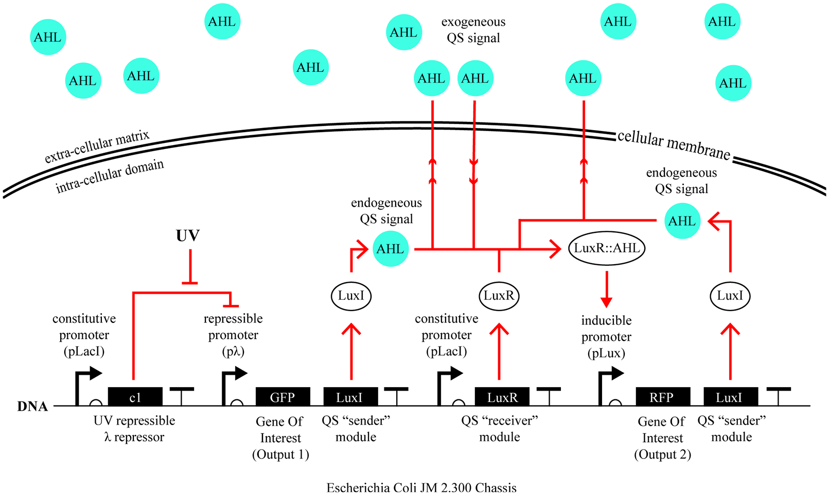
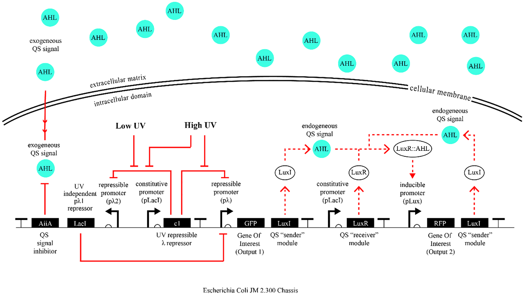
This first iteration of bioPheme’s genetic circuit (Figure 6) enables bacteria to respond only to a single UV intensity. This happens via a double repression pathway between the UV input and the promoter controlling the expression of Output1. In other words, the UV exposure represses the activity of the constitutively produced (i.e., always ON) c1 protein that itself represses the activity of its cognate λ promoter. As a result, when UV reaches the cell, the λ promoter gets turned on because it is no longer being repressed by the c1 repressor. When the λ promoter is turned on by an external UV input in this way, it produces two downstream genes: output 1 and the LuxI protein. In this proof-of-concept circuit, output 1 is assigned to be a fluorescent marker, a Green Fluorescent Protein (GFP), which is a proxy for any other gene that can be inserted in its place (e.g., a gene for the biomaterial of interest).
As a result, by the default state of this circuit, there’s no output being expressed; for this to happen the circuit must be activated by either UV, or an incoming cell-to-cell communication signal. Without either one of these inputs, the constitutively expressed c1 protein is in a state of constant repression of pλ, inhibiting both output 1 and LuxI. Furthermore, because LuxI protein is a precursor for the synthesis of the QS signal, which is a small diffusible molecule called acyl-homoserine lactone (AHL), in this “reset” state, the cell-to-cell communication signal is not being produced, either.
Accordingly, it is only when cells are exposed to UV do they begin to express the protein LuxI, and by extension the diffusible QS signal (AHL). While some amount of this signal freely diffuses outside the cell, into the extracellular milieu, some of it stays inside the cell and binds to the constitutively produced LuxR protein. This binding event results in the formation of an AHL-LuxR complex, which can act as a transcriptional activator when bound to its cognate pLux promoter. Activation of pLux promoter in this way results in the production of its two downstream genes: output 2 and more LuxI protein. This interaction forms the backbone of the quorum sensing signaling mechanism and is shown on Figure 7 in isolation.
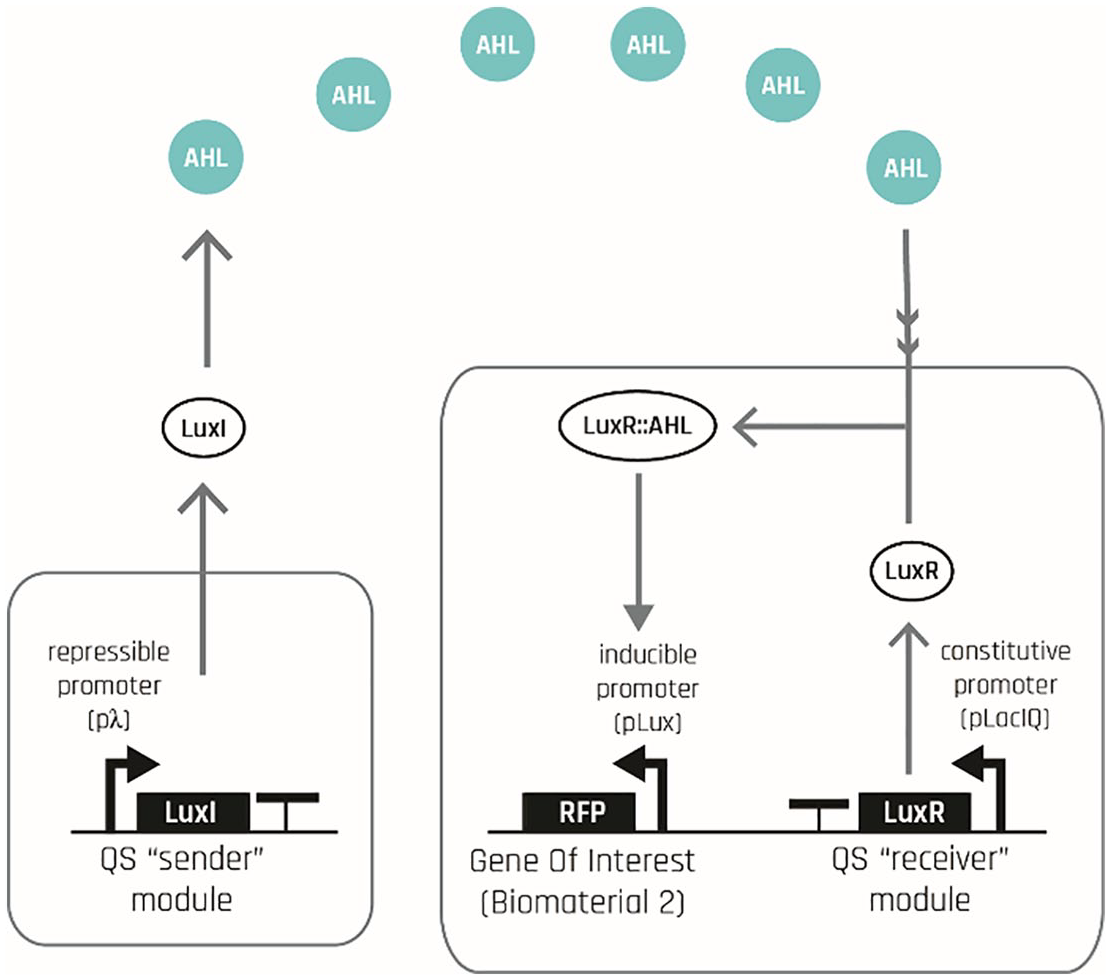
Simple quorum signaling mechanism between two bacterial cells.
As shown on Figure 6, because LuxI is the precursor protein to the signaling molecule AHL, this AHL-activated LuxI protein in turn produces even more of the AHL molecule, and hence forms a positive feedback loop inside the cell. It is this loop of AHL triggering the formation of more AHL that enables the signal to propagate to the rest of the colony, rather than diffuse and die off. This positive feedback loop removes the need for direct UV exposure for a cell to be able to produce the QS signal. In other words, any cell that uptakes the diffusing AHL molecule from the extracellular milieu, even if it has not been directly exposed to UV, can still produce AHL and export some of it back to the extracellular milieu, enabling further propagation of the signal into the rest of the population.
In addition to controlling the expression of this second set of LuxI protein in this way, the pLux promoter also controls the production of the other downstream gene: output 2. As a result, production of output 2 will be observed in all of the non UV exposed regions into which the signal propagates, enabling these cells to produce the second biomaterial (encoded by output 2) in the noUV-yesSignal regions (Figure 8).
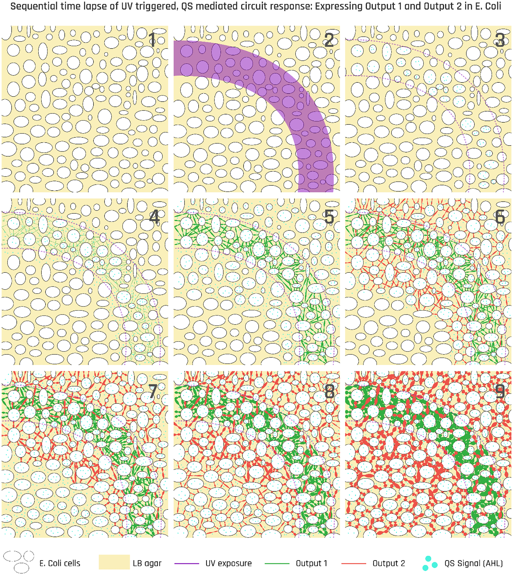
Timelapse diagram showing cells’ response to UV exposure per the first iteration circuit. Every single bacterium in this colony carries the same genetic makeup. Each bacterium, in addition to its own genome, carries the same synthetic genetic circuit we have inserted.
As a result of output 2 being expressed only in the presence of the QS signal, naturally, location where the signal propagation stops determines the outer boundaries of the shape. In other words, for the biomaterial to stop being produced, the QS signal propagation must be stopped in one way or another. In this first iteration circuit, the blockade of signal propagation can be made in one of two ways: one is to simply let the signal propagate until it cannot, that is, have the shape of the container to determine the outer boundaries of the shape. This solution is not desired because it completely contradicts the initial motivation for this work, which is to have the shape formation be independent of the container in which cells are grown. Another way is to trace the boundaries of the shape with a UV intensity that is far beyond what cells can tolerate. Because such an “input” would not trigger any computation inside the cells, but would simply kill them, we consider this option also as a brute force solution that does not necessarily capitalize on living cells’ ability to execute computation. To solve this issue of boundary setting in a way to continue harnessing cells’ internal computational form generation capacity, we created a second iteration of this circuit in which the boundaries of the shape is determined by the constituent cells’ executing spatial computation and silencing the signal. Details of the second iteration is discussed later in this section. Next, we introduce the design, build, test cycle of the UV sensor that is so critical to the overall design and that is explored in this first iteration.
UV sensor: Design, build, test cycle
Once the biodesigner comes up with an initial circuit design, as explained above, next step is to test this circuit in the wet lab to make sure it behaves in the initially intuited way. Thanks to synthetic gene circuits’ modular nature, before constructing and testing the entire circuit, it is possible to test and iterate over a specific sub-module to validate its function in isolation. This allows the designer to troubleshoot the final circuit faster and ensure that the best possible combinations of genetic modules are used.
In our case, we started with the submodule that is the most critical for the overall circuit behavior: the UV sensor. At the heart of the UV sensing and actuation mechanism in our circuit is the c1 protein, which is a very strong repressor, responding to UV in the above explained fashion. Accordingly, because in the above circuit design this strong c1 repressor is placed under a constitutive promoter (pLacI), we hypothesized that this combination may lead to excessive repression of c1’s target sequence (the λ promoter) such that the UV exposure (at the intensity we apply) may not be able to effectively relieve the repression. To test this hypothesis, we have curated a library consisting of eight different combinations of genetic parts (Figure 9), each amounting to a UV sensor, in each of which we have iterated over three variables: the c1 repressor itself, the promoter from which it has been expressed, and its ribosome binding site (RBS) following the promoter sequence. In other words, for each one of eight options in our library of UV sensors, while we kept using a two transcriptional unit architecture (sensing and actuation), we iterated over the sensing unit’s repressor, promoter, and RBS parts: for each part, we chose between either the c1 repressor or its mutant c1*, the constitutive promoter pLacI, or a UV-activated pλ; and finally a RBS30 or aRBS33, respectively.
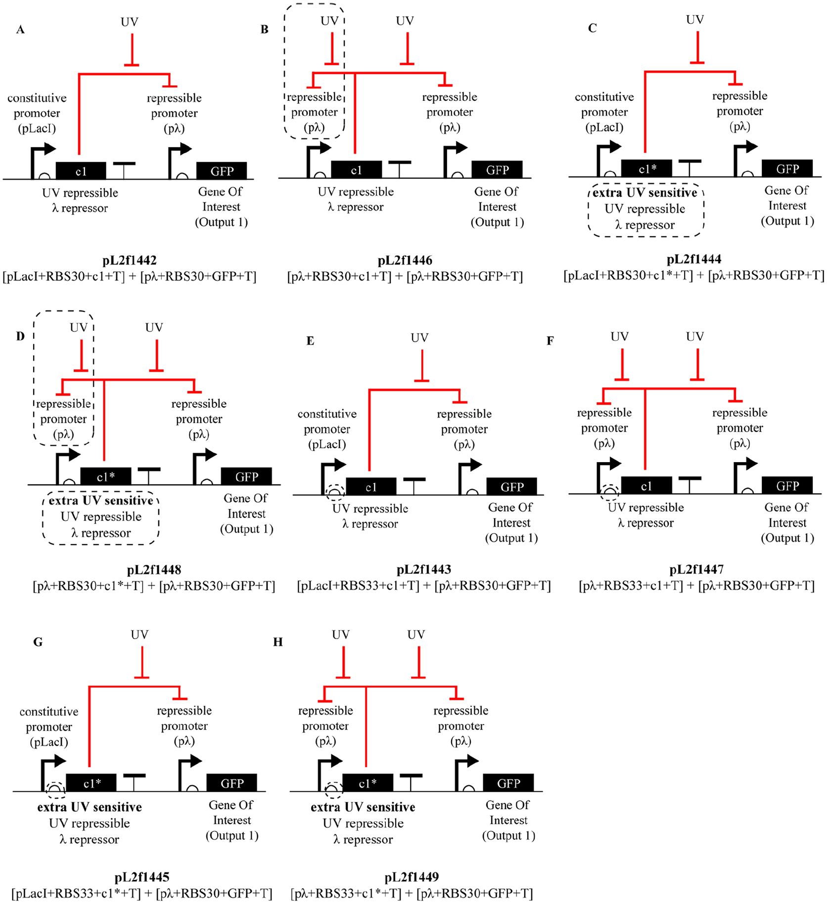
Possible design iterations for the UV sensor.
Reason for testing c1* alongside of c1 is because c1* is a more UV-sensitive mutant, meaning it binds to its target with less strength, hence its repression of the pλ promoter can be more easily relieved via UV exposure at the intensities the bacteria can afford. As mentioned above, another “knob” we can turn on the circuit design for a more responsive UV circuit, is the promoter from which c1 (or c1*) is expressed. In the first iteration circuit design introduced above (Figure 6), we use the pLacI promoter, which due to its constitutive nature is hypothesized to run the risk of overpowering c1, or even c1*, causing the UV sensor module to be unresponsive. To test this hypothesis, we added another promoter as an alternative into our library: c1’s own cognate promoter pλ. Rationale behind this negative feedback loop was the hypothesis that if c1 represses its own production, and is only produced when exposed to UV, its overproduction in the cell may be prevented. And finally, the last iteration was on the RBS placed upstream of the repressor. The original RBS we used was RBS30, which causes the mRNA transcript to tightly bind the ribosome, and hence allow for higher rates of translation. We hypothesized that using a weaker RBS, like RBS30, may decrease the rate of translation, hence attenuating the activity of c1 in the cell. Figure 9 shows all these different combinations of these alternative repressors, promoters and RBSs making up our library.
Once we curated this 23 = 8 options library, next step is to build each option out of DNA, put them into bacteria, and characterize their response to UV exposure using a flow cytometer, allowing us to determine the most robust UV sensor architecture. Results of this characterization experiment are shown in Figure 10.

Flow cytometry data showing all eight architectures’ response to UV induction along with two control plasmids. No UV exposure (left plot) and 10 mJ UV exposure (right plot). Sensor response is measured as the amount of Green fluorescent protein (GFP) that each bacterial population expresses (x axis: “FITC-A”), plotted against the duration since UV exposure (y axis: “incubation duration”).
As seen on Figure 10, the DNA circuit pL2f1443 showed the steepest transfer function with a 10-fold increase in its output activity. It is followed by the pL2f1447, which also showed a 10-fold increase, but it also showed a downward trend upon reaching maximal expression, while the pL2f1443 exhibited a steadier behavior in this critical region.
As a result of this characterization experiment, we decided to move forward with the pL2f1443 construct, which is the option where we place the wild type c1 under the constitutive promoter pLacI complemented with the RBS33. The fact that the common denominator between both best performers is that both have the weaker RBS33, instead of the stronger RBS30, tells us that when it comes to increasing the sensitivity of the UV sensor, translational dynamics (i.e., conversion of the mRNA transcripts into proteins) plays a larger role than the transcriptional dynamics of how strongly c1 is expressed (determined by the promoter), or how tightly it binds its cognate sequence (determined by its own structure, i.e., wild type vs the mutant).
Informed by this experiment, in the second iteration of the genetic circuit below, we decided to switch the RBS upstream of c1 from RBS30 to RBS33. Now that we identified the most optimal sensor architecture in this way, in the second iteration we coupled this sensor architecture to different actuator architectures to identify the combination that yields orthogonal responses to different levels of UV input.
Second circuit design iteration
As explained earlier in this section, the primary purpose of this iteration is to allow for different outputs in response to different levels of UV excitation, enabling bacteria to detect the edges of the shape computationally. Accordingly, in this updated circuit design (Figure 11), we generated two different λ promoter 3 architectures for which the c1 repressor has different affinities. While the promoter for which the c1 has a lower affinity will be able to get activated by lower level of UV exposure, a second promoter for which c1 has higher affinity will require a higher level of UV exposure for c1’s repression of this promoter to be knocked out.
Second iteration circuit’s response in the case of UV exposure can be followed on this circuit diagram.
As a result of these updates, this final design bacterial cells that are exposed to low UV intensity will turn on the gene for output 1, as well as initiate a QS signaling wave. Surrounding cells that receive this signaling molecule and have not been exposed to any UV will turn on the gene for output 2, as well as propagate the QS signal. Cells that are exposed to high UV will turn the gene for the output 3, which is the molecule aiiA, functioning as a “wave breaker” by breaking down the AHL molecule (the QS signal) and thus stops the propagation of the signal (Figure 12).
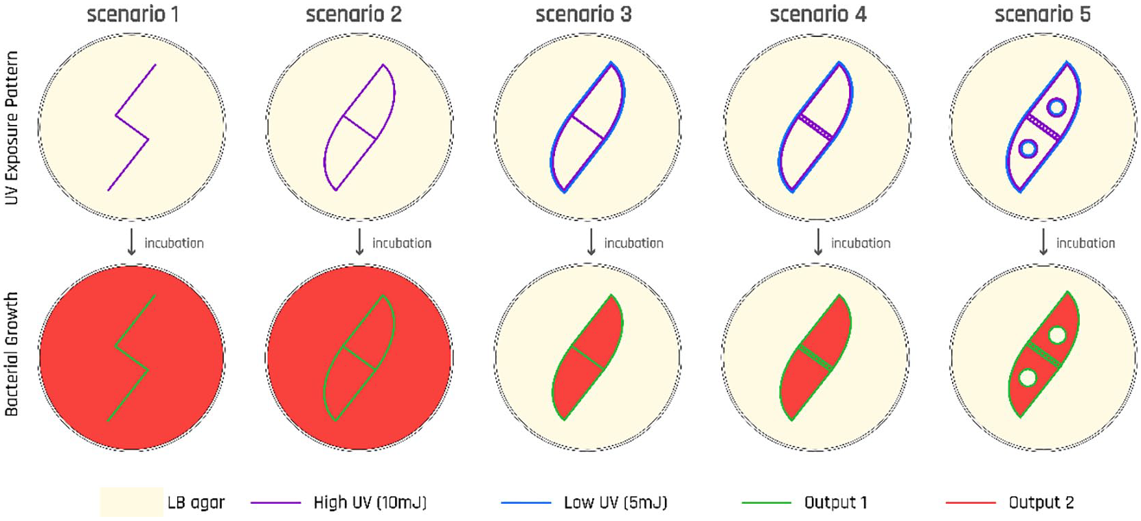
Diagram showing different scenarios for the cells’ response to UV per the second circuit design. As a result of a “killing curve” experiment, details of which is not included here due to space constraints, we have identified 10mJ to represent a “high UV,” and 5 mJ to represent a “low UV” intensity as these energy levels activated our host cells’ SOS pathway without actually killing them.
To achieve this differential response to UV exposure, we followed a similar approach to the characterization of the UV sensor sub-module discussed above: we generated a library of different sub-module architectures for the UV actuator—except that this time we have iterated over two parts: the c1 target promoter, and the RBS sequence following this promoter (Figure 13).
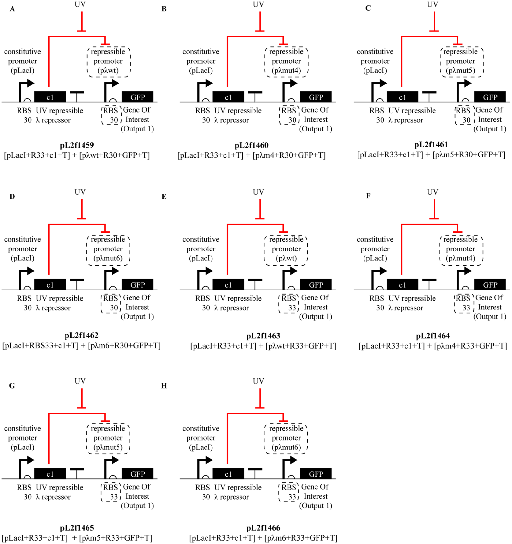
Gene expression library of second iteration.
UV actuator: Design, build, test cycle
In this section we discuss the design, build, test cycle of the different UV actuator modules enabling us to realize the updated circuit design introduced above in Figure 11. In these series of experiments, our goal is to build two orthogonal actuators to satisfy the need of having the circuit to differentially respond to different levels of UV input, which we added as a new design requirement in this second iteration of circuit design.
To achieve this goal, here we create a library of eight options, each is a unique combination between four different promoters and the two RBSs. These four promoters include the wild type λ promoter (pλwt), which we used in the first iteration of the circuit, as well as its mutated versions pλm4, pλm5, and pλm6, which are formed via single, two, and three base pair alterations in wild type pλ’s DNA sequence, respectively. Main difference between these promoters is their affinities for the c1 repressor, which is caused by the indicated mutations on their repressor binding sites (OR sites). And for the two different RBSs, we again use the RBS30, promoting a strong binding of the mRNA transcript to the ribosome, and the RBS33, promoting a weaker binding to the ribosome as introduced in the UV sensor characterization section above. Figure 13 below shows all the different combinations of these alternative promoters and RBSs making up our library.
Once we have curated this 2*4 = 8 options library, in the next step, we built each option out of DNA, put them into bacteria, and characterized their response to UV exposure using a flow cytometer, allowing us to determine the most robust UV actuator architecture. Results of this characterization experiment are shown in Figure 14. It is worth noting that in this set of actuator characterization experiments, as distinct from the previous sensor characterization experiments, we are not going after an optimization problem. Instead, we are trying to find two well-functioning modules, by which we mean modules with distinct ON/OFF states, whose dynamic range falls into different parts of the output spectrum. Such orthogonality is required for different outputs to be mapped into different UV excitation levels.
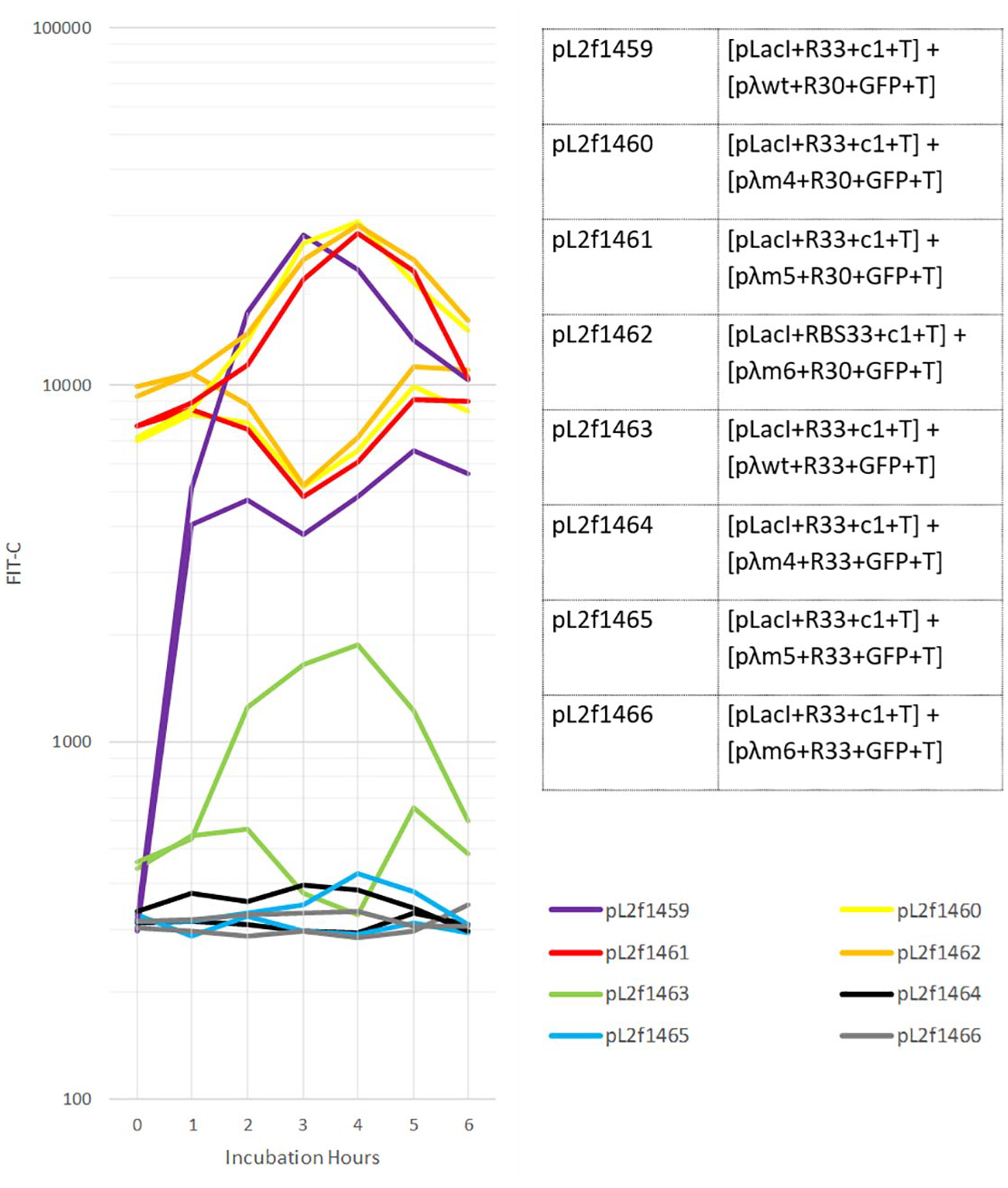
Flow cytometry data showing all eight architectures’ response to UV induction along with two control plasmids.
In the Figure 14 above, responses of eight different bacterial populations to no UV exposure (the bottom curve in each color) and 10 mJ UV exposure (the top curve in each color) is shown. The response is again measured as the amount of Green Fluorescent Protein (GFP) that each bacterial population expresses (x axis: FITC-A), which is the readout from the actuator modules shown on the above library, plotted against the duration of post-UV exposure (y axis: incubation duration). As can be seen on this graph, the pL2f1459 and pL2f1463 constructs together show two distinct and steep transfer functions with each close to 10-fold difference between their ON and OFF states. This means that, assuming we choose appropriate promoters for both outputs, we can use these two sets of actuators to be controlled by different levels of UV and trigger two different output responses.
We believe that the identification of UV sensor and actuator modules in this way is the most critical step for this project’s actualization in the wet lab, given the genetic toolkit for the QS module has already been well characterized in the literature.31,32 As the next step, the biodesigner would put together these sub-modules to create the full design of the circuit introduced on Figure 11. In conjunction with these dynamics, designers can program the output 1 to be the expression of a sturdy substance such as a biomineral, 35 and the output 2 to be a soft and elastic substance, such as cellulose 36 (Figure 15). In this way, we can create objects where the biomineral-based solid superstructure and the cellulose-based softer filling tissue are not only generated by the single input of UV excitation, but are also seamlessly integrated at a single cell resolution.

Rendering showing the envisioned result of scenario 5 on Figure 12 above. Example of a 3D structure formed as a result of 2D fabrication, enabled by the living hinges.
Finally, even though in bioPheme the fabrication process itself unfolds in 2D (Figure 12) this technique can still be used to create 3D structures (Figure 15) as there are various effective methods for transitioning 2D shapes into 3D structures, including living hinges (Figure 12), shape memory alloys, 37 self-folding38,39 and tissue contraction. 40 Although mammalian synthetic biology is a more suitable platform for construction in the third dimension for biodesigners, 41 building 3D structures out of 2D microbial sheets can still be very advantageous as it can allow for fabricating light-weight 3D structures with minimal assembly requirements. This aspect of planar 2D to 3D transition is true for human-made structures, as well as for nature itself where formation of voluminous structures out of planar elements is abundant, for example, the nautilus shell. This is because articulating 2D support elements together for creating a 3D structure is evolutionarily more advantageous for an organism than committing to bulk growth; the former lessens the amount of material used, hence diminishes the metabolic and physical burden on the organism. 3 Such natural structures are valuable examples for architects—not because nature should be taken as a mighty catalog for designers to copy from, but because we can learn much from nature regarding the construction logic that works best when building with biological systems.
Conclusion
In this paper we introduced the novel biofabrication method entitled bioPheme, where the fabrication workflow starts with designer’s specification of the target shape onto a lawn of engineered bacteria using a UV beam (similar to a laser cutter’s UV beam, though with the much less intensity of 10mJ). Once the target shape is traced, which takes in the order of seconds, the workflow proceeds with bacteria taking this UV excitation as an input and accordingly executing the inserted synthetic genetic circuit.
Encoded in this circuit are several complex rules forming feedback loops and combinatorial logic for how bacteria should communicate with one another to autonomously fill in this initially specified shape with the biomaterial of designer’s choice. More specifically, through these rules, bacteria that come in direct contact with the UV stimulus executes a feed-forward loop, resulting in bacteria’s formation of biomaterial A, as well as starts transmitting a cell-to-cell communication signal. This signal can diffuse into the extracellular milieu and propagate across the remaining bacterial population via the positive feedback loop encoded in the circuit. In addition to the activation of this positive feedback motif, receipt of this signal also triggers bacteria to begin generating a biomaterial B in the non-UV-traced parts of the population. Finally, a negative feedback loop motif activated by a higher intensity UV trace enables the cells themselves to assign the boundaries of the shape they create —not the container in which they grow. In this way, by avoiding dependence on external guides, such as molds, that themselves require yet another fabrication step biofabrication can be sustainably scaled up into the realm of centimeters, and even meters. Accordingly, we believe bioPheme to be a critical step toward unlocking biofabrication’s potential for being deployed as an architectural construction method and creating scalable 2D and 3D structures with hybrid material characteristics on-demand. BioPheme can also be practiced in-situ and thus be used for construction in “extreme” locations, into which transportation of traditional construction machinery and material is prohibitively expensive, such as isolated locations on Earth like deserts, oceans or high-altitude regions, or even in outer space.
Finally, in this paper, in the course of describing the technical details of our bioengineering proposal to the community of architects we offer a map of the inscrutable world of biotechnology and help bridge these disparate communities which are surprisingly similar in motivations despite their substantial differences in methods. We offer a few key metaphors to guide a reader familiar with architectural computation into the world of biotechnology—in particular, synthetic biology—that undergird the proposal in this paper. For example, bacteria may be viewed as computers, with communication as broadcast packets rather than point-to-point communication. The underlying genetic mechanisms correspond roughly to well-known computational methods with enough accuracy that understanding the proposed method without training is feasible, though not easy. With the awareness that the subject matter of the document is new or even intimidating to our audience—as it was for the author at the outset of bridging these two communities—we encourage the reader to follow the technical citations, which we have selected not only for their technical value but also for their accessibility for readers who are interested in understanding the potential of harnessing nature in unprecedented ways to advance our field of architectural computation.
Footnotes
Acknowledgements
The work presented in this paper was designed, conducted, and completed during the author’s dual-degree studies at the Massachusetts Institute of Technology’s Department of Architecture and the Department of Electrical Engineering and Computer Science. The author acknowledges Nicholas DeLateur’s technical contributions to the characterization of the submodules library for genetic circuits using a flow cytometer. The author conducted this independent study in the Laboratory of Ron Weiss at the MIT Department of Biological Engineering.
Declaration of conflicting interests
The author declared no potential conflicts of interest with respect to the research, authorship, and/or publication of this article.
Funding
The author disclosed receipt of the following financial support for the research, authorship, and/or publication of this article: Funding for this work was provided in the form of a Graduate Fellowship from the MIT Department of Architecture.