
Abstract
Hybrid girihs refer to Islamic geometric patterns that include various stars/rosettes in their final pattern. In this paper, we first identified historical hybrid girihs and then categorized them based on symmetry groups and the number of stars/rosettes folds. In the next step, we analyzed the existing hybrid girihs to identify the generative parameters and present a method for generating historical and novel systematic and non-systematic hybrid girihs. The proposed method of this paper is a computational and parametric approach based on the symmetry groups theory. Its general steps include generating the minimal essential information (template motif) within the fundamental region, applying appropriate symmetry operations on the content of the fundamental region to create the content of the unit girih, and replicating the content of the unit girih in a suitable network according to the symmetry group to create the whole pattern. Our method is used to generate hybrid girih for adorning surfaces in digital spaces and for constructing facade modules (adorned with Islamic geometric patterns) and interior decorative partitions and furniture in physical spaces according to the aesthetic judgment of users.
Introduction
The advancement of contemporary technology, the rise of ideas like interactive and responsive architecture, and the integration of movable or shape-changing building elements suggest that structures could become significantly more versatile and adjustable. 1 Interactive and adaptable architecture involves constructing buildings that can swiftly adapt to changes throughout their lifespan. 2
In computational architectural design, project goals are achieved by analyzing parameters and variables. The concept of computational and interactive architecture is centered around achieving a balance of mutual interactions between these parameters and variables. This approach also involves user participation in defining relationships and controlling the final design. 3
Interactive architecture is a digital system that combines hardware and software to create architectural behaviors like shape or form change. 4 Changes in the physical aspect of interactive architecture are driven by adjustments in the software parameters. The hardware component lags behind the software due to tool complexity and high costs, resulting in many designs lacking a tangible presence. However, the rise of virtual spaces, fueled by technologies like virtual reality, augmented reality, and mixed reality, has opened up new opportunities for architects to explore the concept of metaverse. 5 This allows for computational thinking and an interactive architectural approach without the constraints of the physical world. For this purpose, Generative parameters by specialized creators (architects) should be identified for good 3D user experiences.
According to the above, architects with computational thinking must identify generative parameters for implementing design algorithms on digital platforms. Architects must be prepared to engage in this new space and strive to transfer valuable aspects of physical architecture to digital platforms and the metaverse. Iran’s traditional architecture holds significant cultural heritage elements that need to be decoded and integrated into this new 3D realm to safeguard them and enhance the quality of the metaverse. The girihs (Islamic Geometric Patterns) that embellish traditional Iranian architecture, rooted in mathematics, present a suitable opportunity for deciphering their generative parameters and applying their algorithms on digital surfaces, enabling the creation of various Islamic geometric patterns.
Islamic geometric patterns are a sacred art and a visual expression of the order of universe creation. 6 The proportions used in these patterns are rooted in the study of nature and matter.7,8 They are a rich source of visual data with compelling combinations of shapes in regular geometric configurations. The regularity of these visual data aids in their mental processing. 9 Symmetry in Islamic geometric patterns creates a sense of harmony through mirroring and repeating units. 10 While these patterns may appear complex at first, their structure gradually becomes understandable due to proper order, arrangement, symmetrical operations, and indicator marks. 11
Islamic art has evolved over time and influenced regions worldwide. Various cultures and artistic styles from different countries have left their mark on this art form. Today, we can see a great variety of Islamic geometric patterns that, despite their diversity and intricacy, share a common foundation and structure. Iranians have long utilized a variety of ornaments in their architecture. Before the advent of Islam in Iran, human and animal figures were the primary decorative elements. However, with the rise of Islam in Iran, geometric patterns, plant motifs, and calligraphy became prevalent in architectural design. Islamic geometric patterns, known as girih in Iran,12,13 are abstract designs that indirectly refer to God. 14 Girihs gradually spread in Iran, evolved, and became more complex during different dynasties and eras. In Iran, girihs are categorized into six-point, 8-point, 10-point, 12-point, and hybrid girihs based on the type and number of stars/rosettes they feature. 15
This paper focuses on hybrid girihs and presents a computational and parametric method based on the symmetry group theory to generate traditional and novel hybrid girihs. The method involves a systematic procedure starting from establishing the basic information required (template motif) to create a particular symmetry type within the fundamental region to replicating the unit girih on a two-dimensional surface using an appropriate grid. (Refer to 16 to learn about symmetry groups, definitions of the fundamental region and the unit cell, and the generation process of patterns and designs based on the symmetry groups theory).
The other sections of this paper are organized as follows: “
Related works
The scientific aspect of Islamic geometric patterns motivates researchers and scientists to decode these intricate designs. Extensive research has been conducted in this field, focusing on studying, evaluating, and categorizing these patterns.14,17-22 Several studies have been dedicated to proposing techniques for creating Islamic geometric patterns.14,15,23-39 The most important of these are the Polygonal Infrastructure Network,14,23-30 the Radial Infrastructure method,15,33 and the method based on Symmetry Groups Theory.31,32
The polygonal infrastructure network method, known as Hankin’s method or polygons-in-contact (PIC), was first explained by Hankin based on his discoveries of semi-finished Islamic geometric patterns.23-26 Building on this, Kaplan 27 introduced a method to create Islamic star patterns. He 28 used Lee’s method 38 to construct patterns in regular polygons. Kaplan and Salesin 29 used inflation tiling to create star patterns based on regular polygons’ symmetry axes. Bonner 14 has conducted extensive studies on decoding Islamic geometric patterns. His main focus is on the polygonal technique and using historical documents to validate it. Bonner proposes two approaches for creating polygon networks: systematic and non-systematic. The systematic approach comprises five types: regular polygon system, 4-fold system type A, 4-fold system type B, 5-fold system, and 7-fold system. In the non-systematic approach, polygons are formed using radial matrices.
There are also historical documents supporting the radial method, such as the Tashkent scroll, based on which Bodner introduced this technique. 33 Contemporary masters of Islamic geometric patterns in Iran typically utilize the radial infrastructure network method to create girihs.15,40
Symmetry is intertwined with Islamic geometric patterns, and the symmetry groups theory is a scientific approach to explaining these patterns. We can see point, frieze, and wallpaper symmetry groups in the substructure of Islamic geometric patterns.17,21 The geometrical order under the foundation of these patterns is resulted by using appropriate symmetry operations, which provide the possibility of replicating these patterns on a wide scale.
Some researchers have employed symmetry group theory to classify, analyze, and create Islamic geometric patterns. Khamjane and Benslimane 32 presented a computerized method to generate Islamic star and rosette patterns. Azizi Naserabad and Ghanbaran, 31 by filling the gap in previous research, 32 presented a method to construct geometric girihs in all four families: acute, middle, obtuse, and two-point that Bonner has introduced.14,30 Other Computerized methods based on symmetry group theory are also accessible for generating Islamic geometric patterns.41,42 Furthermore, there are comparable methods capable of constructing Islamic self-similar and quasi-periodic patterns.39,43,44 Several studies have been carried out in this area to classify patterns,17-19 as well as to analyze and recognize Islamic geometric patterns using symmetry group theory.19-21,45
Our proposed method in this paper falls under the category of methods based on symmetry groups theory. So far, there has been no comprehensive study on hybrid girihs, nor has there been an exclusive digital method for constructing them. The main objective of this paper is firstly, to study hybrid girihs and secondly, to present a digital method for generating hybrid girihs. Our method produces a greater variety of girihs than those created using the infrastructure polygonal networks.14,29 Additionally, it generates hybrid girihs in all four families: acute, middle, obtuse, and two-point (The proposed method in 32 only covers girihs in three families: acute, middle, and obtuse).
Although the method presented in 31 generates girihs in all four families: acute, middle, obtuse, and two-point, it does not cover hybrid girihs. Our proposed method in this paper aims to provide a rail-based method (similar to the method presented in 31 ) that can construct a wide range of novel hybrid girihs in addition to the existing ones.
Hybrid girihs refer to girihs with various stars/rosettes in their final pattern.
40
In this paper, we categorize hybrid girihs into two types: − Systematic hybrid girihs: Stars/rosettes are centered at the vertices of the fundamental region in these girihs. − Non-systematic hybrid girihs: Stars/rosettes are found not only at the vertices of the fundamental region but also within or on its boundary in these girihs.
We start by studying systematic hybrid girihs and propose a method for creating them in section 3; subsequently, in section 4, we unveil unique hybrid girihs and explain the process of constructing them.
Systematic hybrid girihs
As mentioned, systematic hybrid girihs have various stars/rosettes centered at the vertices of the fundamental region. For example, the 12/9-point girihs, which Bodner has presented methods for drawing them,33,34 are systematic hybrid girihs. Bodner has pointed out that these girihs have Persian origin and were first observed in documents and buildings related to Iran. Both of these girihs are classified in the p6m symmetry group (girihs 1 and 2 of Table 1). Table 1 shows the various systematic hybrid girihs we collected from different references14,15,32-34,40,46 and redrew at the unit girih scale. Preliminary reviews of systematic hybrid girihs show points as follows: − These girihs are either in the p6m or p4m symmetry group. − In terms of the number of various stars/rosettes in the final pattern, hybrid girihs are either 2-star/rosette girih or 3-star/rosette girih. Historical and existing hybrid girihs.
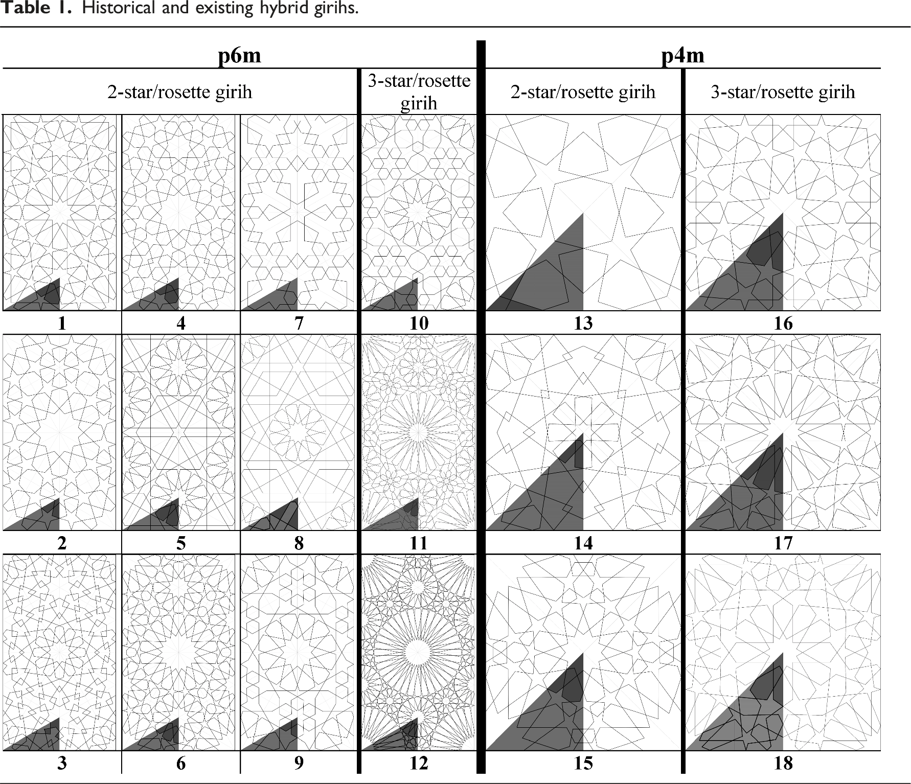

The design of Table 1, which includes two columns: p6m and p4m, and two sub-columns: 2-star/rosette girih and 3-star/rosette girih, is based on the points mentioned above.
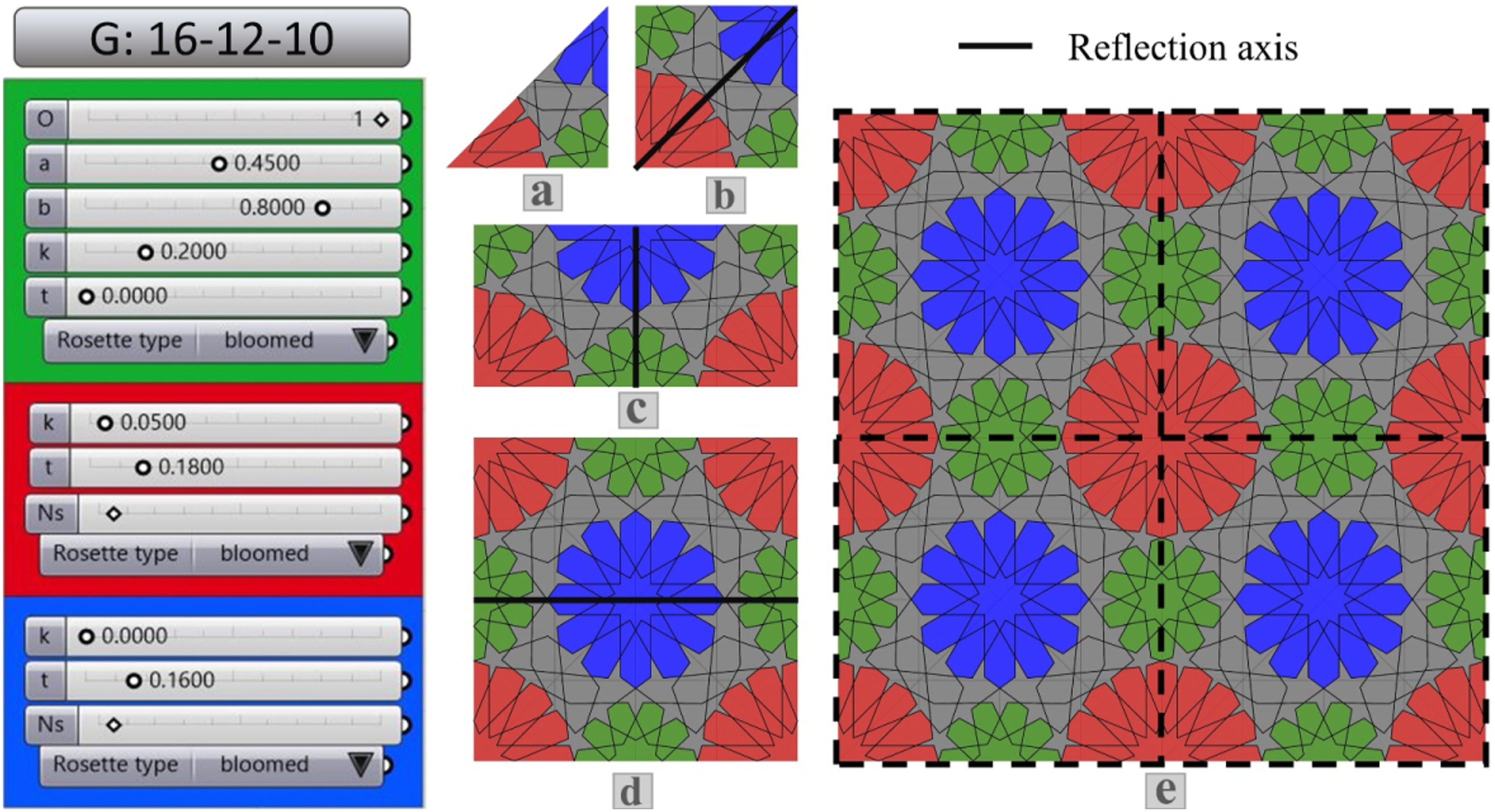
Figure 1 shows the fundamental region, the replication unit, the suitable net for replicating the content of the replication unit, and the symmetry operation used for the p6m (Figure 1(a)) and p4m (Figure 1(b)) symmetry groups. In this paper, we have used the unit girih as the replication unit. The unit girih is used in the radial infrastructure network method as a replication module to draw girihs.15,40 By dividing the unit girih into equal triangles, the fundamental regions of two p6m and p4m symmetry groups are created (the 90-30-60 triangle for the p6m symmetry group (Figure 1(a)) and the 90-45-45 triangle for the p4m symmetry group (Figure 1(b))). All three vertices of these two triangles are the centers of rotational symmetry; In the triangle of p6m, vertex A is the center of 6-fold, vertex B is the center of 3-fold, and vertex C is the center of 2-fold rotational symmetry. In the p4m triangle, vertices A and B are the center of 4-fold, and vertex C is the center of 2-fold rotational symmetry. The fundamental region, the replication unit, the suitable net for replicating, and the symmetry operations of the p6m and p4m symmetry groups.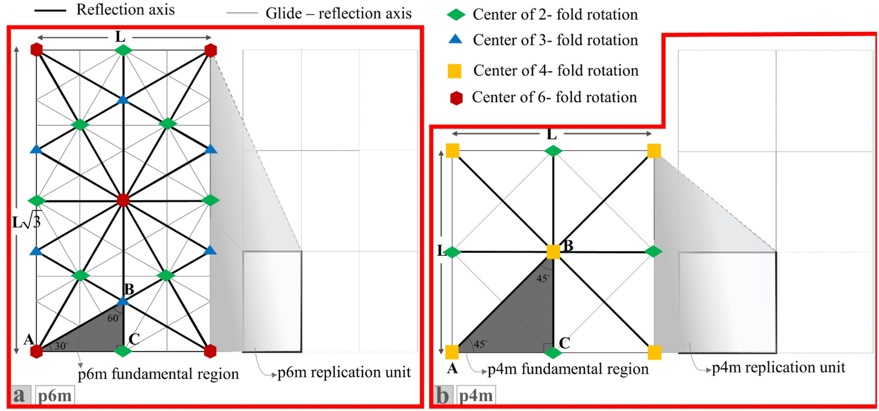
In Table 1, the fundamental region of each girih is specified on it. By comparing the number of folds of the stars/rosettes, which their centers are at vertices of the fundamental region (triangle ABC (Figure 1)), with the rotational symmetries that occur at each vertex, it can be concluded that at each vertex of triangle ABC, the number of folds of stars/rosettes is a multiple of the number of folds of the rotational symmetries. For example, a 36/18/12-point girih is a p6m hybrid girih that the star/rosette placed at the vertex A has (6*6)36 folds, the star/rosette at the vertex B has (3*6)18 folds, and the star/rosette at the vertex C has (2*6)12 folds (girih 12 of Table 1). A 16/12/10 girih is a p4m hybrid girih that the star/rosette placed at the vertex A has (4*4)16 folds, the star/rosette at the vertex B has (4*3)12 folds, and the star/rosette at the vertex C has (2*5)10 folds (girih 18 of Table 1).
Analysis
In this section, we will delve deeper into the systematic hybrid girihs presented in Table 1 to extract the necessary morphological information to establish the method for constructing systematic hybrid girihs.
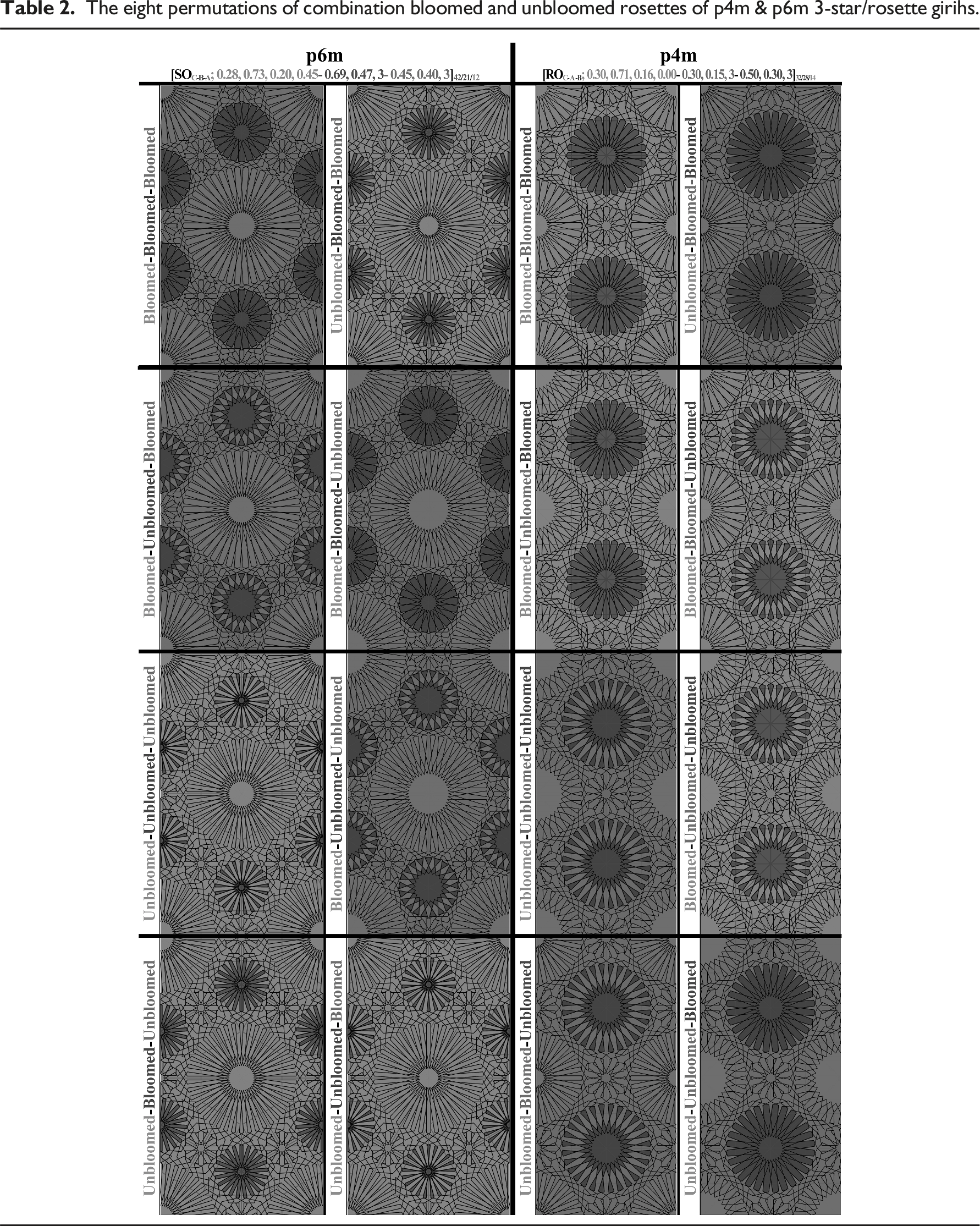
As the first point, rosettes of hybrid girih not only can be different in terms of the number of folds but also can be different structurally. Rosettes are of two types: bloomed and unbloomed (See Fig. 4 of reference [31]). We can see the combination of these two types in the final patterns of hybrid girihs (girihs 3, 5, 7, and 8 of Table 1). Therefore, the proposed method of this paper should cover both types of rosettes.
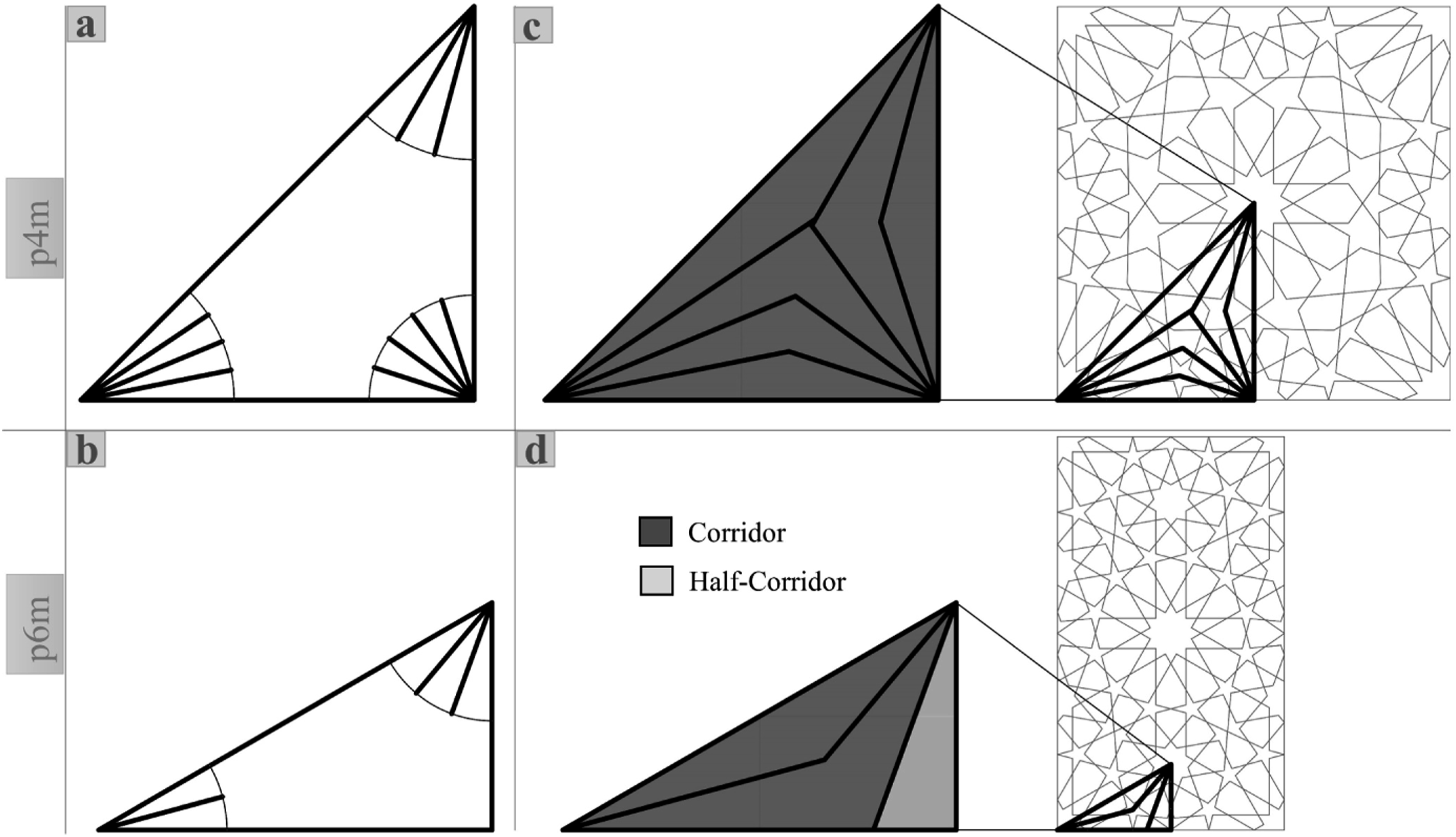
For better analysis of systematic hybrid girihs, we create corridors within the fundamental regions (Figure 2). The contents of these corridors are parts of the template motif (the content of the fundamental region) that connect the counterpart half-folds of the stars/rosettes. These corridors are created by the collision of radii extracted from the vertices of triangle ABC (Figure 2(c) and (d)). These radii divide the angle of each vertex into equal angles. The number of divisions of angles How to create the corridors within the fundamental region for hybrid girihs.
For example, in a p4m 16/12/10-point girih, the number of divisions of angles
By examining and analyzing the girihs of Table 1, we can present the following explanations about hybrid girihs:
Two-star/rosette systematic hybrid girihs
2-star/rosette systematic hybrid girihs include girihs have stars/rosettes at the vertices A and B (Table 1; 2-star/rosette girihs except girihs 7 and 13), or A and C (Table 1; girihs 7 and 13) of fundamental regions. In 2-star/rosette girihs, we can see a great variety of stars/rosettes combinations (in terms of the number of folds), with the condition that the number of folds of each star/rosette is a multiple of the rotational symmetry folds of the corresponding vertex of fundamental regions. For example, Figure 3 shows 2-star/rosette girihs have 18-fold rosettes at vertex A, and the rosettes of vertex B can be 3N-fold rosettes; N is an integer greater than 1, and three is the number of the rotational symmetry folds of vertex B. The possibility of construction of various 2-star/rosette girihs.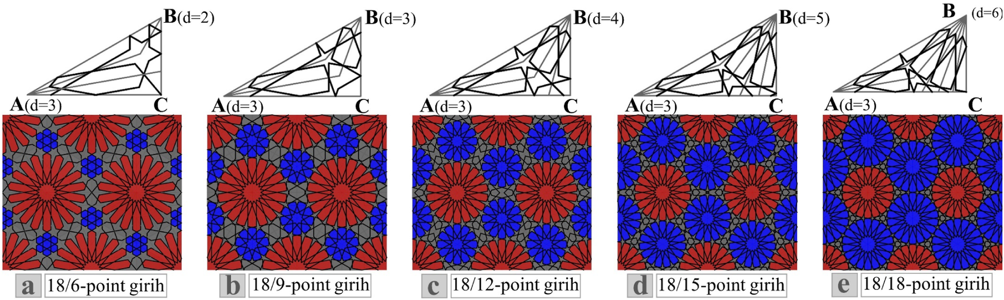
In general, three situations occur for 2-star/rosette hybrid girihs: 1- The number of divisions of angle 2- The number of divisions of angles 3- The number of divisions of angle
Three-star/rosette systematic hybrid girih
In the final patterns of 3-star/rosette systematic hybrid girihs, we can see star/rosette at three vertices of triangle ABC. In 2-star/rosette hybrid girihs, because there is no star at one vertex, it makes us not have any restrictions in the combination of stars/rosettes. But in 3-star/rosette hybrid girihs, this freedom does not exist. In these girihs, the combination of stars/rosettes within the fundamental region should be such that all the template motif is placed within the corridors (in this case, we do not have half-corridors (Figure 2)). Therefore, the corridorization of the fundamental region of 3-star/rosette hybrid girihs should be such that no triangles (half-corridors) are created, and we only see corridors in this region. For this purpose, we must consider the following conditions in the creation of corridors within the fundamental region of 3-star/rosette hybrid girihs (For the case that we consider vertex C of the fundamental region as the starting point of girihs construction): − If the number of divisions of angle Creation of the corridors within the fundamental region for 3-star/rosette girihs based on the description of Section 3.2.

For example, if the number of divisions of angle −If the number of divisions of angle

For example, if the number of divisions of angle
The proposed method
Figure 5 is a graphical representation of the entire process of creating the template motif of systematic hybrid girihs within the fundamental region. As you can see, 3-star/rosette girihs have more construction phases. Therefore, the proposed method of this paper is described in more detail for these girihs. We can use the method for 2-star/rosette girihs with one less phase. Graphical representation illustrating the creation of the template motif for systematic hybrid girihs within the fundamental region.
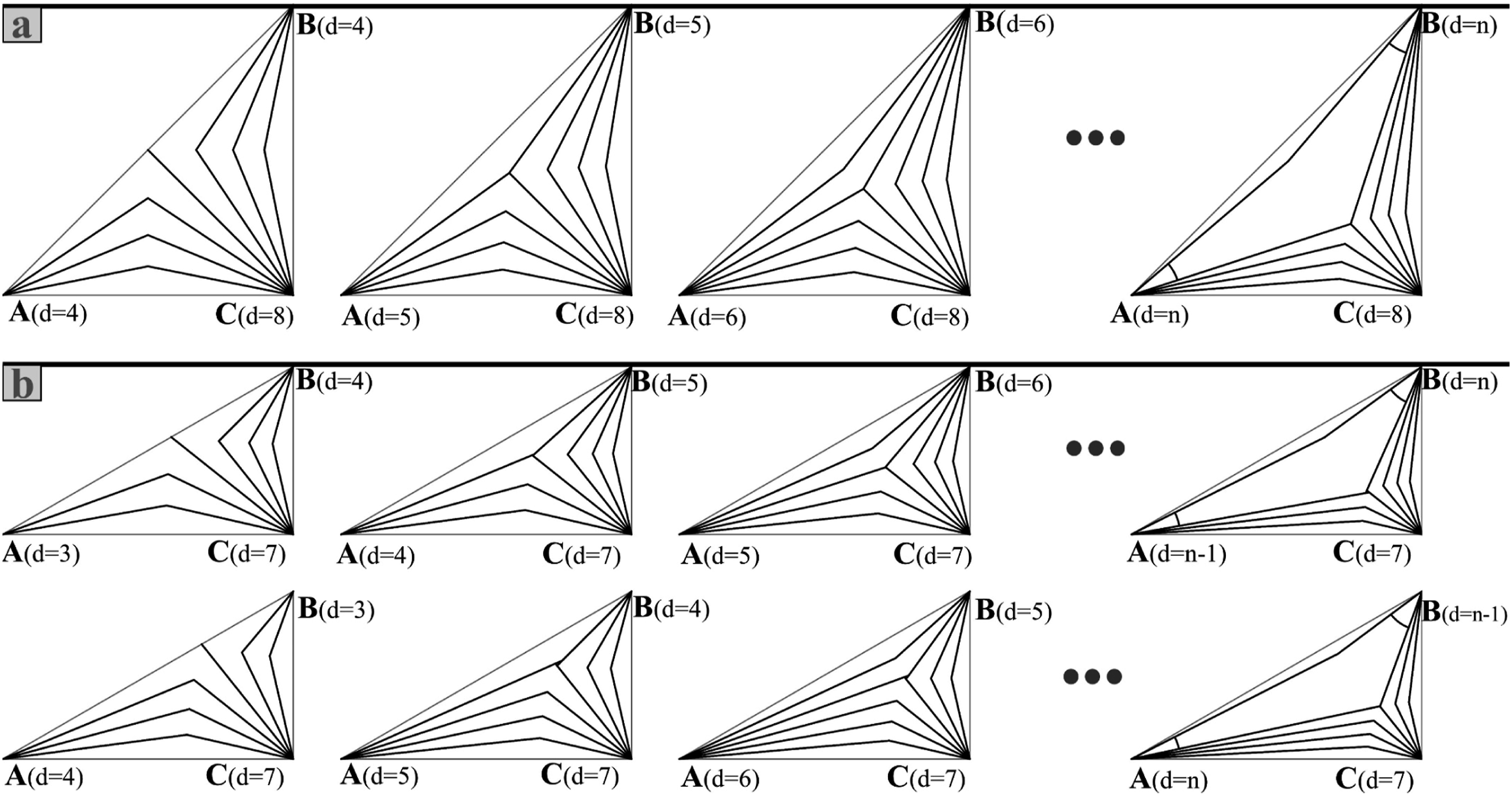
The process of generating hybrid girihs can be started from any of the vertices (A, B, or C) of the fundamental region (triangle ABC). From any vertex we start, the girihs construction phases are similar, but the variety and combinations of girihs in each state can be different. Figure 6 shows the hybrid girihs with different beginnings of the girih construction process. In Figure 6(a), the girih generation process begins from vertex A. In Figure 6(b), the process starts from vertex B, and in Figure 6(c), the process triggers from vertex C. In Figure 6, the number of divisions of vertices, at which the construction process begins, is equal in all three girihs, but the final pattern of those is different. Hybrid girihs with different beginnings of the girih construction process. The start of the girih construction process in a is vertex A, in b is vertex B, and in c is vertex C.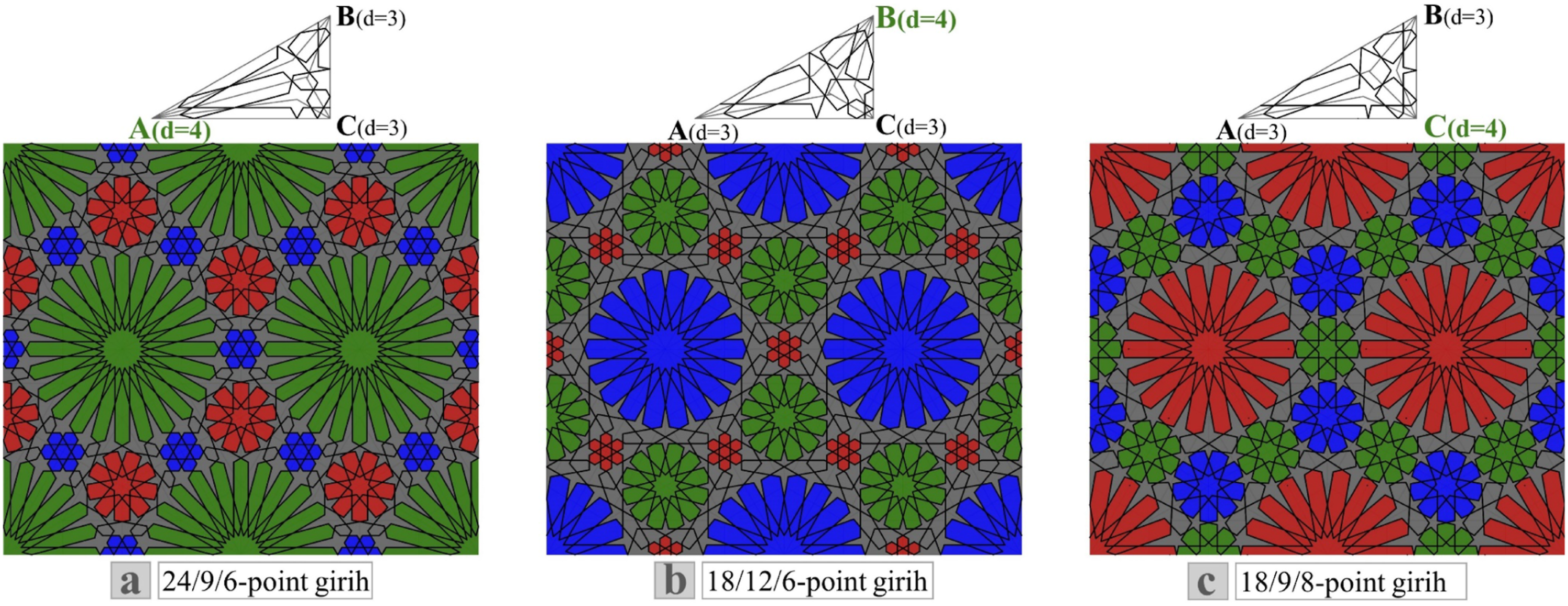
In this paper, we consider vertex C as the starting point of the hybrid girihs construction process. To generate 3-star/rosette girihs, we propose four main phases as follows (We describe these four phases in the fundamental region of p4M hybrid girihs (Figure 5: the blue path). These phases are similar for the p6m hybrid girihs):
First phase: Construction of line M and its successive mirror reflections (creating motifs around vertex C)
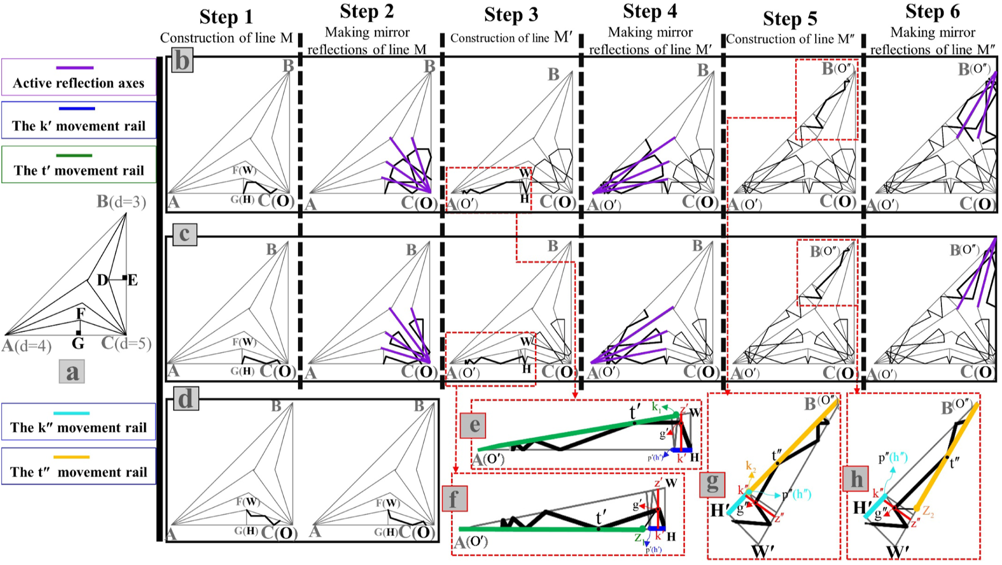
First, outline the radial grids within the fundamental region to create generative corridors and draw lines from points D and F perpendicular to BC and AC at points E and G (Figures 7(a) and 8(a)). Compare the dimension of CE and CG; If CE is smaller, consider triangle CDE as the generative region (Figure 7; Step 1). If CG is shorter, consider triangle CFG as the generative region for constructing line M (Figure 8; Step 1). The methods presented in previous works can be used to generate line M. We chose the rail-based method
31
to construct this line because it is more comprehensive and fills the gaps of other works. Triangle CDE or CFG is analogous to the triangle OWH, and line M is equivalent to the lines S and S′.
31
After creating line M, using the radii extracted from vertex C as symmetry axes, reflect it successively to create a part of the template motif near vertex C (Figures 7 and 8; Step 2). The construction process of lines M, M′, and M′′. The construction process of bloomed (b) and unbloomed (c) rosette patterns.
Second phase: Construction of line M′ and its successive mirror reflections (creating motifs around vertex a or B)
The last segment of line M intersects with WH in one of the following cases: − At point H (Figures 7(b) and 8(b); Step 1) − At a point other than W and H (Figures 7(c) and 8(c); Step 1) − At point W (Figures 7(d) and 8(d))
If the last segment of line M meats WH at point H, apply mirror reflection to it (WH is the mirror reflection axis) and extend it to reach OʹW or OʹH at point rʹ (Figure 7(b); Step 3). If the last segment of line M meats WH at a point other than W and H, extend it to reach OʹW or OʹH at point rʹ (Figure 7(c); Step 3). r 1 rʹ is the first segment of the Mʹ line that acts like a light ray after meeting OʹW or OʹH reflected successively towards Oʹ (vertex A or B).
If the last segment of line M meats WH at point W, it is not possible to create correct hybrid girihs. This is because the interesting property of Islamic geometric patterns, which is the formation of an X by the straight segments at each point of intersection, is violated. Generally, as the intersection of the last segment of line M and WH gets closer to Point W, it becomes impossible to construct appropriate hybrid girihs.
Third phase: Construction of M′′ line and its successive mirror reflections (creating motifs around vertex B or A)
Similar to the previous phase, the last segment of line Mʹ (within triangle OʹWʹHʹ) intersects with WʹHʹ in one of the following cases: - At point Hʹ - At a point other than Wʹ and Hʹ - At point Wʹ
If the last segment of line Mʹ meats WʹHʹ at point Hʹ, apply mirror reflection to it (WʹHʹ is the mirror reflection axis) and extend it to reach OʺWʹ or OʺHʹ at point rʹ. If the last segment of line Mʹ meats WʹHʹ at a point other than Wʹ and Hʹ, extend it to reach OʺWʹ or OʺHʹ at point rʺ. r 2 rʺ is the first segment of line Mʺ, and similar to r 1 rʹ, it acts like a light ray and creates the Mʺ line after successive reflections towards Oʺ (Figure 7; Step 5).
During the successive reflection process of lines Mʹ and Mʺ, their direction is reversed at a point (qʹ & qʺ). When this happens, the end of lines Mʹ and Mʺ are determined, and the segments of Mʹ and Mʺ that have inverse movement are not part of them (in Figure 7 (step 3&5), the red line segments are not part of Mʹ and Mʺ).
If the last segment of line M′ intersects with W'H' at point W′, it also becomes impossible to create correct hybrid girihs. Here too, the closer the intersection point of the last segment of line M′ and W'H' to point W′, the more challenging it becomes to construct appropriate hybrid girihs.
As illustrated in Figure 7, to create the rosette patterns near Oʹ (vertex A or B) and Oʺ (vertex B or A), we implement the refraction idea for lines Mʹ and Mʺ. For this purpose, we consider lines zʹkʹ and zʺkʺ that move on rails h´H and hʺH´ (hʹ(hʺ) is the meeting point where the pʹhʹ(pʺhʺ) line is perpendicular to OʹH (OʺH′) and pʹ(pʺ) is the start point of the last segment of line Mʹ (Mʺ)) and at points gʹ and gʺ intersect Mʹ and Mʺ and causes they to be refracted (Figure 8; Step 3&5). zʹkʹ and zʺkʺ can intersect any segment of lines Mʹ and Mʺ except pʹqʹ and pʺqʺ (the last segment of Mʹ and Mʺ) and cause they to deviate. In general, based on the refraction of Mʹ (Mʺ) at point gʹ (gʺ), two types of bloomed and unbloomed rosette patterns are generated: − If the start of a segment line of Mʹ (Mʺ) that collides with zʹkʹ (zʺkʺ) is on OʹH (OʺH′), the end of the first segment of line Mʹ after refraction (gʹtʹ (zʺkʺ)) will be on OʹH (OʺH′) to create the unbloomed rosette (Figure 7(f)) and be on OʹW (OʺW′) to construct the bloomed rosette (Figure 7(e)). − If the start of a segment line of Mʹ (Mʺ) that collides with zʹkʹ (zʺkʺ) is on OʹW (OʺW′), the end of the first segment of line Mʹ (Mʺ) after refraction (gʹtʹ (zʺkʺ)) will be on OʹW to create the unbloomed rosette (Figure 8(h)) and be on OʹH (OʺH′) to construct the bloomed rosette (Figure 8(g)).
Consider rails k 1 Oʹ (k 2 Oʺ) and z 1 Oʹ (z 2 Oʺ) for the movement of point tʹ (tʺ) to control the refraction angle by changing the position of tʹ (tʺ). k 1 (k 2 ) is a point where when we extend the last segment of line Mʹ (Mʺ) before refraction, it meets OʹH (OʺH′) or OʹW (OʺW′). z1 (z 2 ) is also the intersecting point of extension of the mirror reflection of the last segment of Mʹ (Mʺ), before refraction, with OʹH (OʺH′) or OʹW (OʺW′) (Figure 8(e)–(h)). After refraction, the Mʹ (Mʺ) line continues its successive reflections after colliding with OʹH (OʺH′) and OʹW (OʺW′) towards Oʹ (Oʺ) until the direction of its movement is reversed. The patterns of Figure 7 are a kind of rosette pattern with the condition that zʹkʹ & zʺkʺ are on WH & W'H' and tʹ & tʺ are on point k 1 & k 2 respectively.
Due to the consecutive reflections, segments of line Mʹ (Mʺ) may be many, and all of them may not be required in the final pattern. For this purpose, consider a parameter to control the number of Mʹ (Mʺ) segments. We show this parameter with NS (Number of Segments). NS is an integer; Its lowest value is 2 for rosette patterns and its highest value is equal to the maximum number of Mʹ (Mʺ) segments due to consecutive reflections after refraction.
NS cannot be less than two for rosette patterns because the first segment of Mʹ (Mʺ) after refraction is incomplete and is complemented by the last segment before refraction. The second segment after refraction also determines the shape of the star, and for star formation near Oʹ (Oʺ), there must be at least one complete segment after refraction. Figure 9 shows the different values of this parameter and the effect it can have on the final shape of patterns. In Figure 8(b), NS = 3; In this case, rosette patterns are created with the 3-layer structure introduced in 47. The effect of the NS parameter on the final shape of the rosette patterns.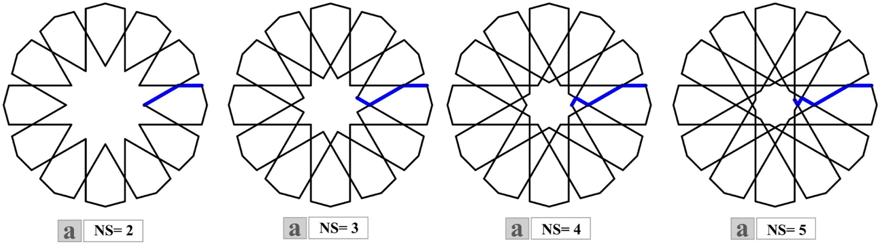
After forming line Mʹ and Mʺ, using the radii extracted from Oʹ (vertex A or B) and Oʺ (vertex B or A) as symmetry axes, reflect it successively to create a part of the template motif near Oʹ and Oʺ (Figure 8; Steps 4&6).
Fourth phase: Construction of interstitial motifs
Interstitial motifs of Islamic geometric patterns are usually very diverse. There is always a basic algorithm for interstitial motifs that can be combined with secondary algorithms to create various interstitial motifs. In this paper, we present the method of creating basic interstitial motifs.
At this step, within the corridors where the final motif has not yet been completely created, extend lines M, Mʹ, and Mʺ towards the red lines that pass through the center of the corridors (Figure 10; Step 7). Corresponding motif segments within each corridor, when reaching the red lines, either meet each other at one point (Figure 10; Step 7 (the green corridors)) or intersect the red lines with a distance (Figure 10; Step 7 (the blue corridors)), in which case, the last segments of the corresponding motifs must be extended to meet each other at a point, and this point must not be outside the corridor (Figure 10; Step 8). By doing these actions for all corridors with incomplete motifs, the interstitial motifs and then the template motifs are created (Figure 10; Step 9). If the last segments of corresponding motifs intersect each other outside of their respective corridor, an appropriate template motif for generating hybrid girihs is practically not constructed. The construction process of interstitial motifs. (a), (b), (c), and (d) are related to Figures 6(b), (c), 7(b), and (d), respectively.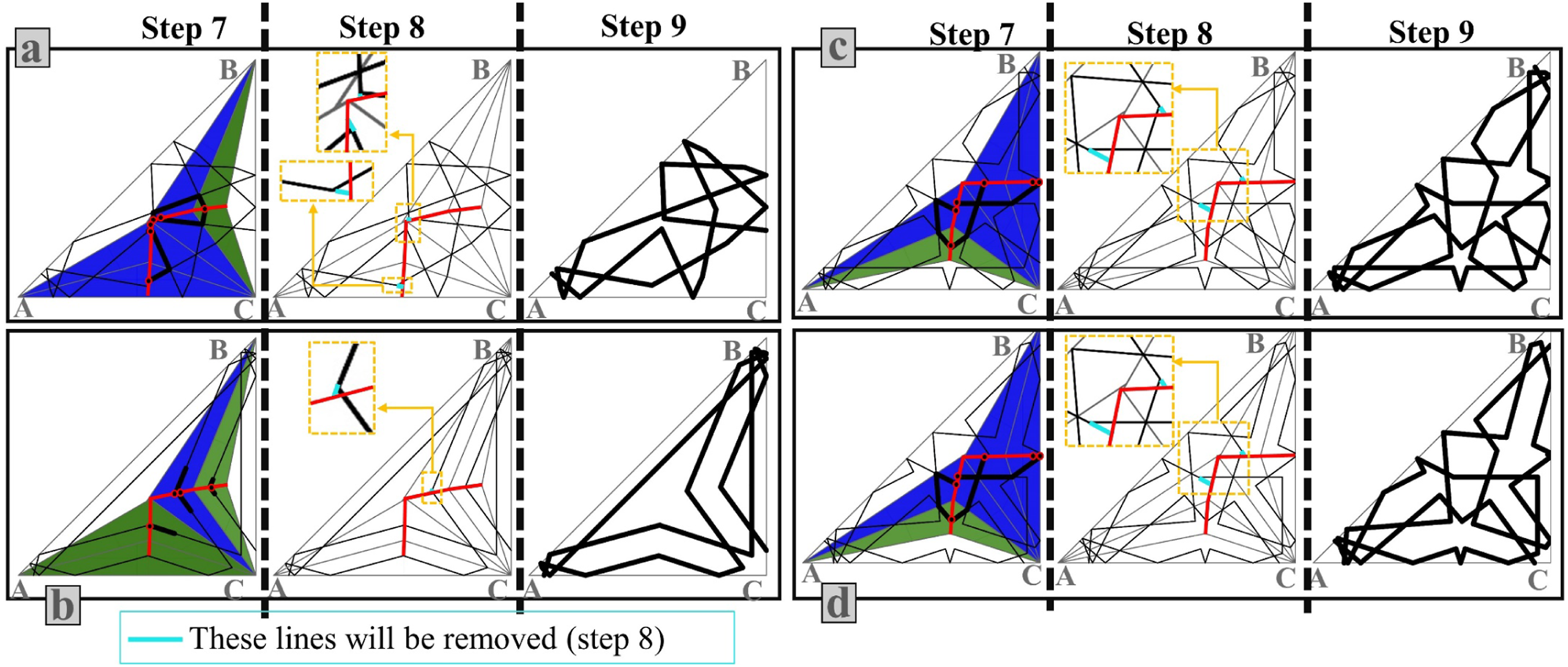
In these four phases, we presented how to create the template motif of 3-star/rosette hybrid girihs within the fundamental region. Figure 11 shows the unit girihs created by applying the appropriate symmetry operation (Figure 1) on the content of the fundamental region of systematic hybrid girihs, whose construction procedures are detailed in Figures 7, 8, and 10.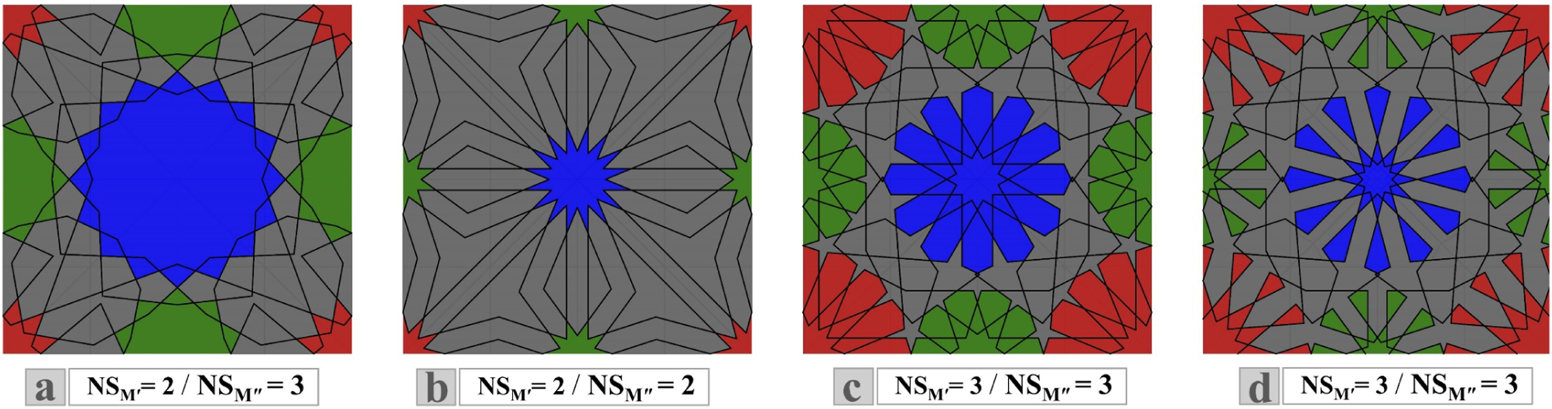
Notation system
In this section, we introduce a notation system for the generative parameters of hybrid girihs. Some parameters of these girihs are the same generative parameters introduced for constructing line M: O, Po a , Po b , Po k , Pot, and G. 31 The O parameter indicates the orientation of single-star/rosette girihs that is straight (SO) or rotated (RO). For hybrid girihs, we show this parameter with a two-letter or three-letter subscript. For example, SO C-A-B is a generative parameter for a 3-star/rosette hybrid girih in which the girih generation process starts from vertex C, then motifs near vertex A, and finally motifs near vertex B are created.
The G parameter specifies the number of star/rosette folds of single-star/rosette girihs. For hybrid girihs, we show this parameter as a combination of two or three numbers representing the number of stars/rosette folds. For example, G = 18/12/6 is a parameter for a 3-star/rosette hybrid girih with an 18-fold star/rosette at vertex A, a 12-fold star/rosette at vertex B, and a 6-fold star/rosette at vertex C.
Based on the descriptions and conditions of Section 4, other generative parameters of hybrid girihs are as follows: − Po
k
ʹ: is the position of point kʹ (Intersection of zʹkʹ and OʹH), which its movement
domain
is from hʹ (start) to H (end) (Figure 8(e) and (f)). − Potʹ: is the position of point tʹ, which its movement domain is from k
1
(start) to Oʹ (end) or z1 (start) to Oʹ (end) (Figure 8(e) and (f)). − NS
Mʹ
: is a parameter to control the number of Mʹ segments. − Po
kʺ
: is the position of point kʺ (Intersection of zʺkʺ and OʺHʹ), which its movement domain is from hʺ (start) to Hʹ (end) (Figure 8(g) and (h)). − Po
t
− NS
Mʺ
: is a parameter to control the number of Mʺ segments.


According to the introduced parameters, the following notation systems can be suggested for all girihs: − For 1-star/rosette girihs
31
: [O; Poa, Pob, Pok, Pot]G − For 2-star/rosette (hybrid) girihs: [O; Poa, Pob, Pok, Pot - Pokʹ, Potʹ, NSMʹ]G − For 3-star/rosette (hybrid) girihs: [O; Poa, Pob, Pok, Pot - Pokʹ, Potʹ, NSMʹ- Pokʺ, Potʺ, NSMʺ]G
Implementation
So far, we have provided the generation method for creating template motifs of P6M and P4M hybrid girihs. 2-star/rosette hybrid girihs can be created by any combination of stars/rosettes, in terms of the number of stars/rosettes folds, at vertices A&B or A&C (With this condition: at each vertex, the number of folds of stars/rosettes is a multiple of the number of folds of the rotational symmetries).
In 3-star/rosette hybrid girihs, there must be a half-fold of stars/rosettes at each vertex for each half-fold at other vertices to be within a corridor and generate part of the template motif by combining the lines propagating from them. To allow this to be possible, the divisions of angles − If the number of divisions of the basis vertex (the vertex from which the girihs generation process starts) is even, the number of divisions of other vertices must be equal. − If the number of divisions of the basis vertex is odd, the number of divisions of other vertices must be one even and one odd with a difference of 1.
We have implemented the algorithm of the method described in this paper in Grasshopper for Rhino 7 for Win. In this algorithm, we have chosen vertex C as the basis vertex to start the girihs generation process and considered the maximum number of divisions of angles
The first step in the implementation process of the proposed method of this paper is the creation of the fundamental region for the p6m and p4m hybrid girihs (Figure 12). How to define the fundamental region of p4m and p6m symmetry groups in Grasshopper.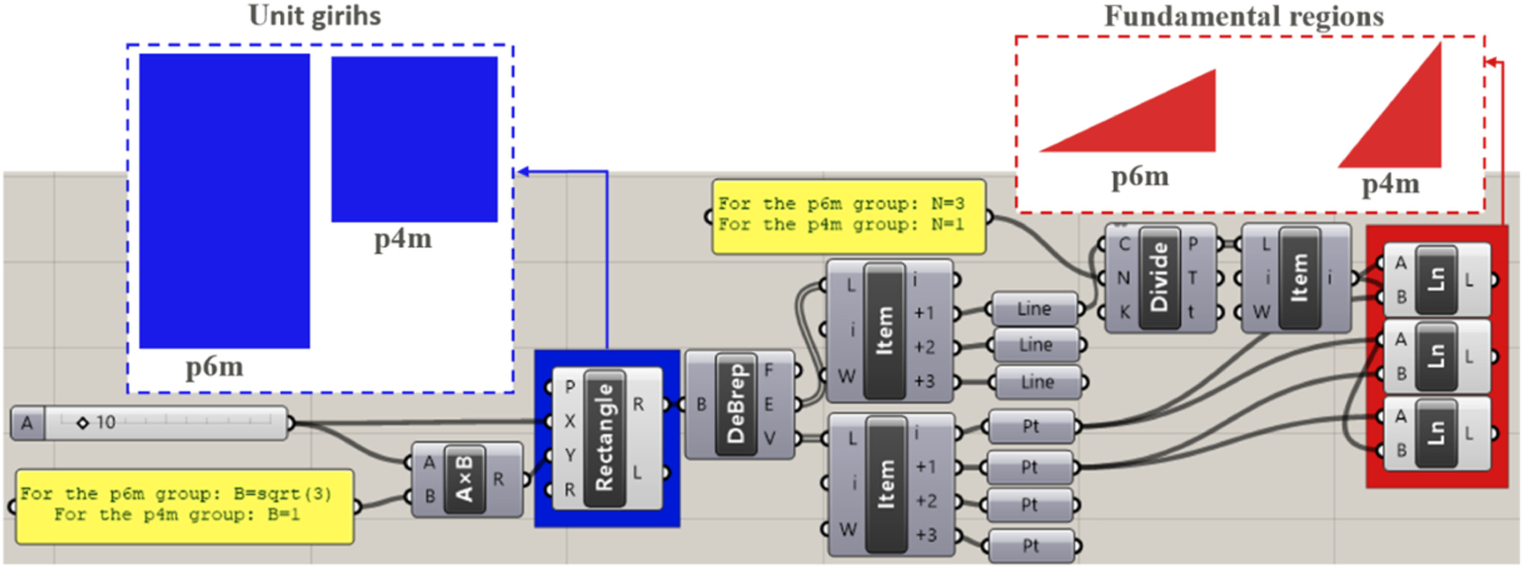
After defining the fundamental region, the template motif can be generated based on the description of Section 4. Applying symmetry operations appropriate to each symmetry group on the content of the fundamental region to generate the content of the unit girih and replicating the content of the unit girih in a suitable net are other steps of implementation process, which are specified in Figure 13 (for p6m hybrid girihs) and 14 (for p4m hybrid girihs). The steps of implementing the method of this paper in the software platform for p4m hybrid girihs. The symmetry operations, which we use, are specified in each step. (a) is the template motifs within the fundamental region. In (b), (c), (e), and (f), we use a reflection axis to mirror motifs. In d, we use a 2-fold rotation to rotate the motifs 180°. (f) is the content of the unit girih, and (g) is the replicated unit girih in a suitable net. The steps of implementing the method of this paper in the software platform for p4m hybrid girihs. The symmetry operations, which we use, are specified in each step. (a) is the template motifs within the fundamental region. In (b), (c), and (d), we use a reflection axis to mirror motifs. (d) is the content of the unit girih, and e is the replicated unit girih in a suitable net.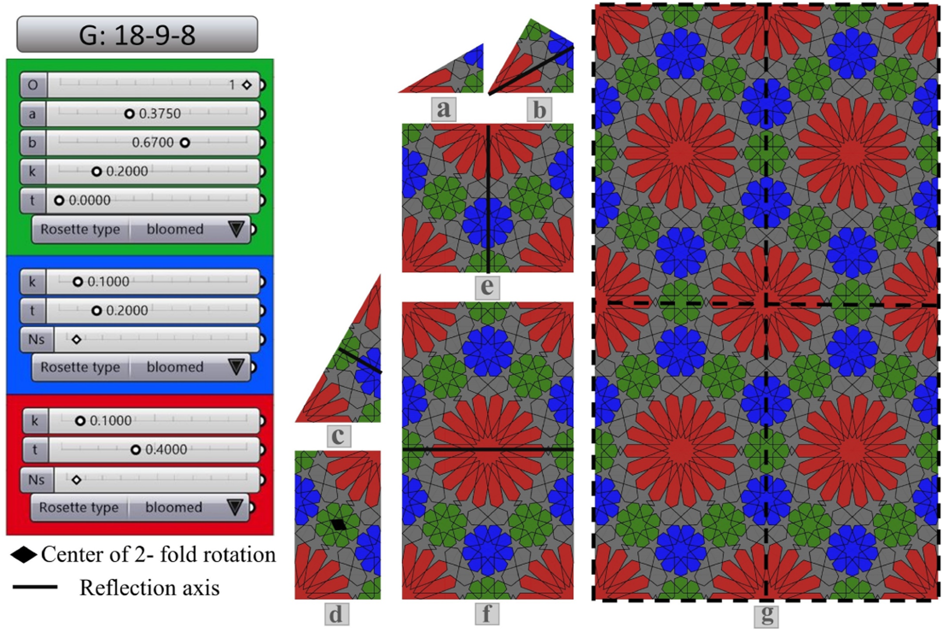
The eight permutations of combination bloomed and unbloomed rosettes of p4m & p6m 3-star/rosette girihs.

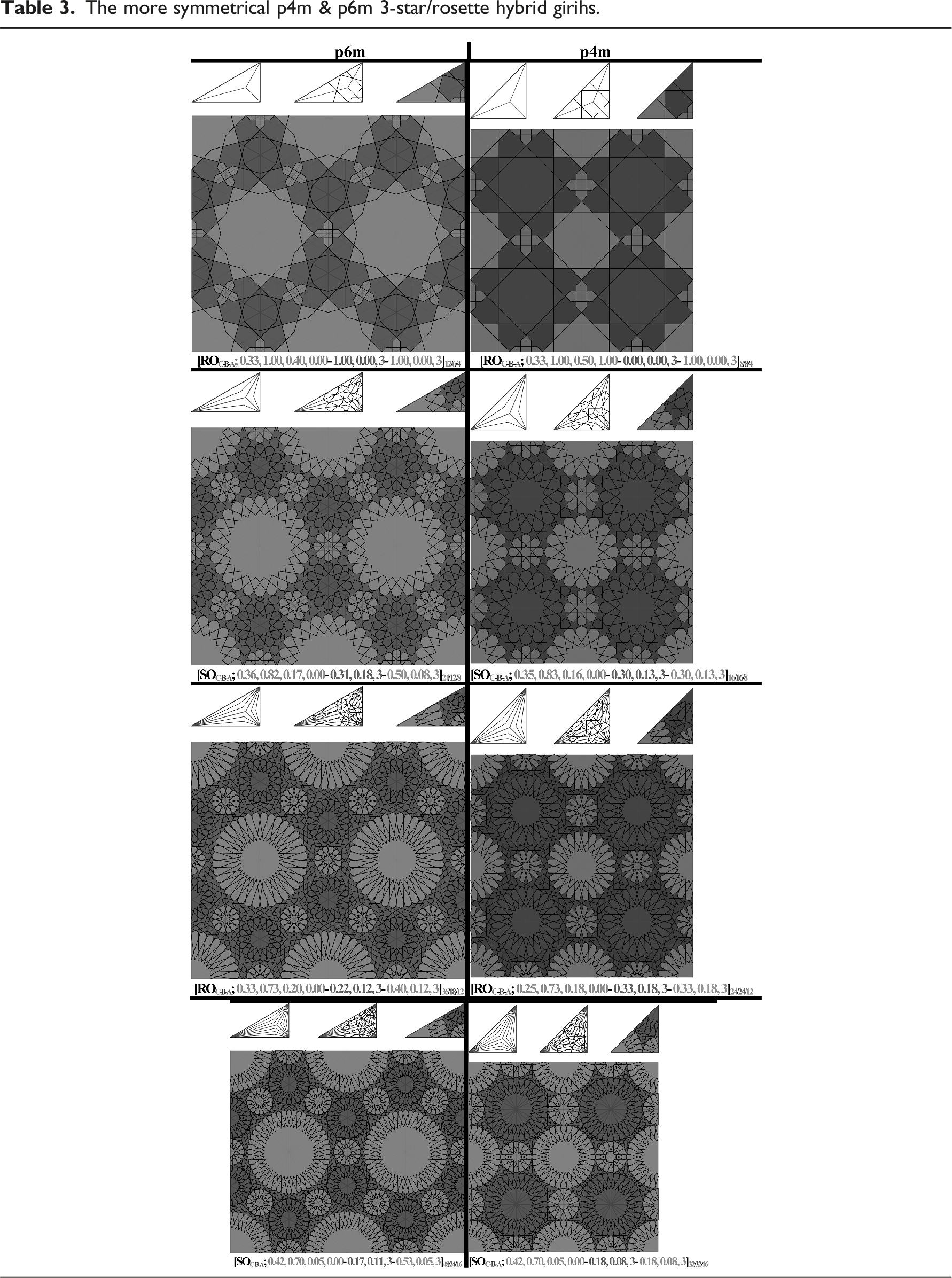
The more symmetrical p4m & p6m 3-star/rosette hybrid girihs.

Non-systematic hybrid girihs
Non-systematic hybrid girihs not only have stars/rosettes at the vertices of the fundamental region but also have stars/rosettes that are centered within and on the boundary of the fundamental region.
Non-systematic p4m hybrid girihs
We begin this section by introducing a case of p4m hybrid girihs having a rosette within the fundamental region (Figure 15).
40
Analyzing and evaluating this girih helps us to generate non-systematic examples of hybrid girihs using the corridorization and the motif construction process (with more steps) presented in Section 4. The historical case of Non-systematic p4m hybrid girih.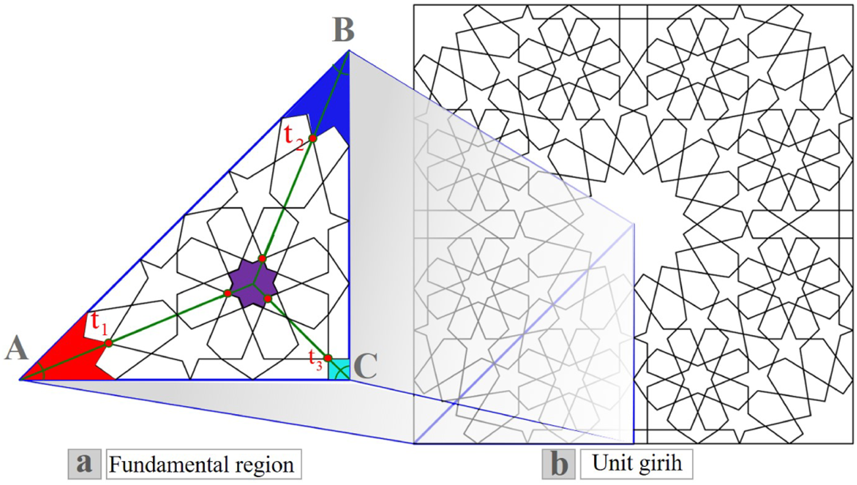
Examining Figure 15 shows the following points: − The star located within the Fundamental region is an 8-point star centered at the intersection of the bisectors of the interior angles of the triangle ABC. − The stars centered at the vertices A and B are 16-point stars, one of whose vertices intersect the bisectors of angles − The star centered at the vertices C is a 4-point star, one of whose vertices intersect the bisector of angle
According to the above point, it can be concluded that to construct hybrid girihs with the configuration of the girih shown in Figure 15, the number of folds of the stars/rosettes centered at vertices A and B must be a multiple of 8, and the number of folds/rosettes of the star centered at vertex C must be a multiple of 4. In this case, the bisectors of the interior angles of triangle ABC are used as middle lines in the corridorization process, and the number of folds of the star/rosette centered at the intersection of these bisectors is a multiple of 8.
It is possible to continue adding 8N-point stars/rosettes within the fundamental region among at least three stars/rosettes and generate hybrid girihs with more stars/rosettes (Figure 16; this process can be continued ad infinitum). Adding stars/rosettes to p4m systematic hybrid girihs to construct non-systematic hybrid girihs.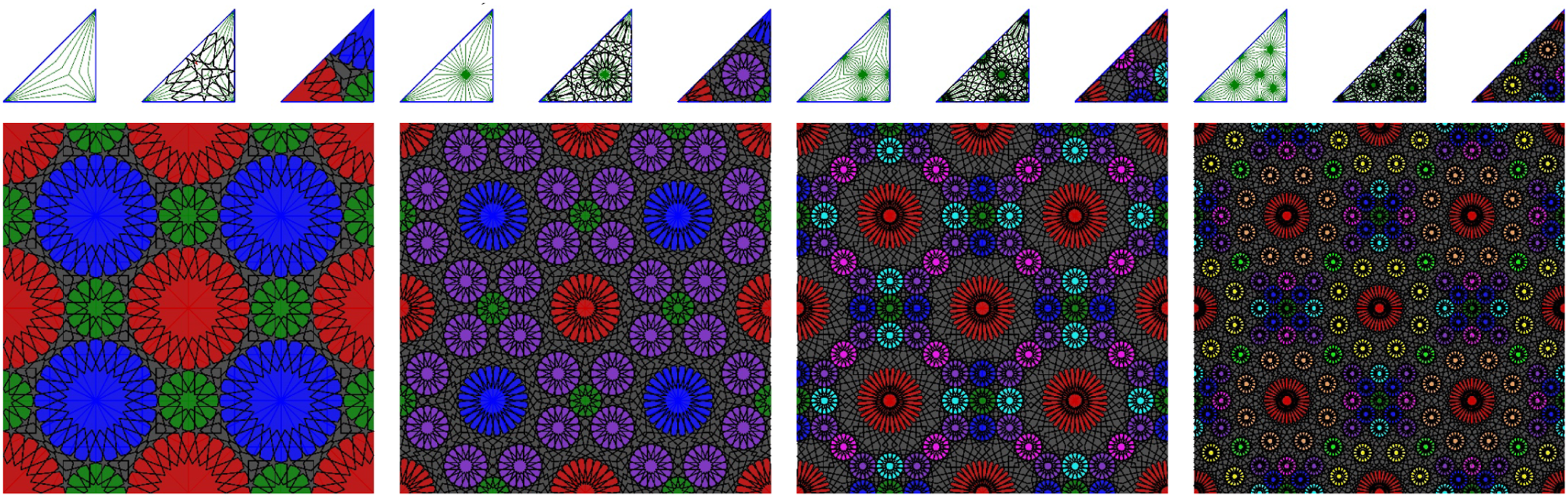
Non-systematic p6m hybrid girihs
We investigated the possibility of generating p6m hybrid girihs similar to the girih shown in Figure 15 by drawing the bisectors of interior angles of triangle ABC: It was found that to construct such a girih, the number of folds of the stars/rosettes centered at vertex A, B, and C must be a multiple of 12, 6, and 4 respectively so that the number of folds of the star/rosette centered at the intersection of the bisectors is a multiple of 12.
It is possible to continue adding 12N-point stars/rosettes within the fundamental region among at least three stars/rosettes and generate hybrid p6m girihs with more stars/rosettes (Figure 17; this process can be continued ad infinitum). Adding stars/rosettes to p6m systematic hybrid girihs to construct non-systematic hybrid girihs.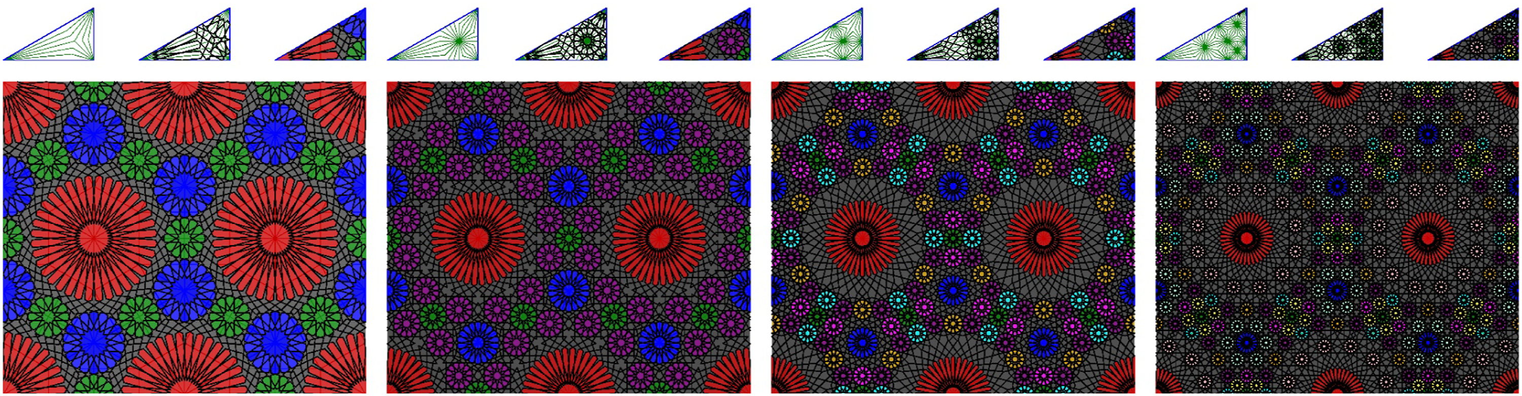
Non-systematic 5&7-fold hybrid girihs
Even and odd 5&7-fold girihs have different structures.
31
This difference is due to different fundamental regions and unit girihs (Figure 18). In the pattern of 5&7-fold girihs, there is a star/rosette centered at two vertices (A&B) of the fundamental region (Table 4, column 1). Because in the fundamental region of the 5&7-fold girihs, the two specified parts (Figure 18) are mirror reflections of each other, we can’t add a new star/rosette at the other vertex(es). Therefore, adding a star/rosette to the structure of these girihs should be done in a way so that the condition of mirror reflection of the specified parts (Figure 18) is fulfilled. After various investigations, we could add a 10N-point star/rosette and a 14N-point star/rosette to the even and odd 5-fold and 7-fold girihs at point P (P is the end of the MP reflection axis in Figure 18) respectively (Table 4, column 2). The unit girihs (replication unit) and fundamental regions of 5&7-fold girihs; (a): odd 5-fold girihs, (b): even 5-fold girihs, (c): odd 7-fold girihs, even 7-fold girihs. Adding stars/rosettes to 5&7-fold girihs to construct hybrid girihs.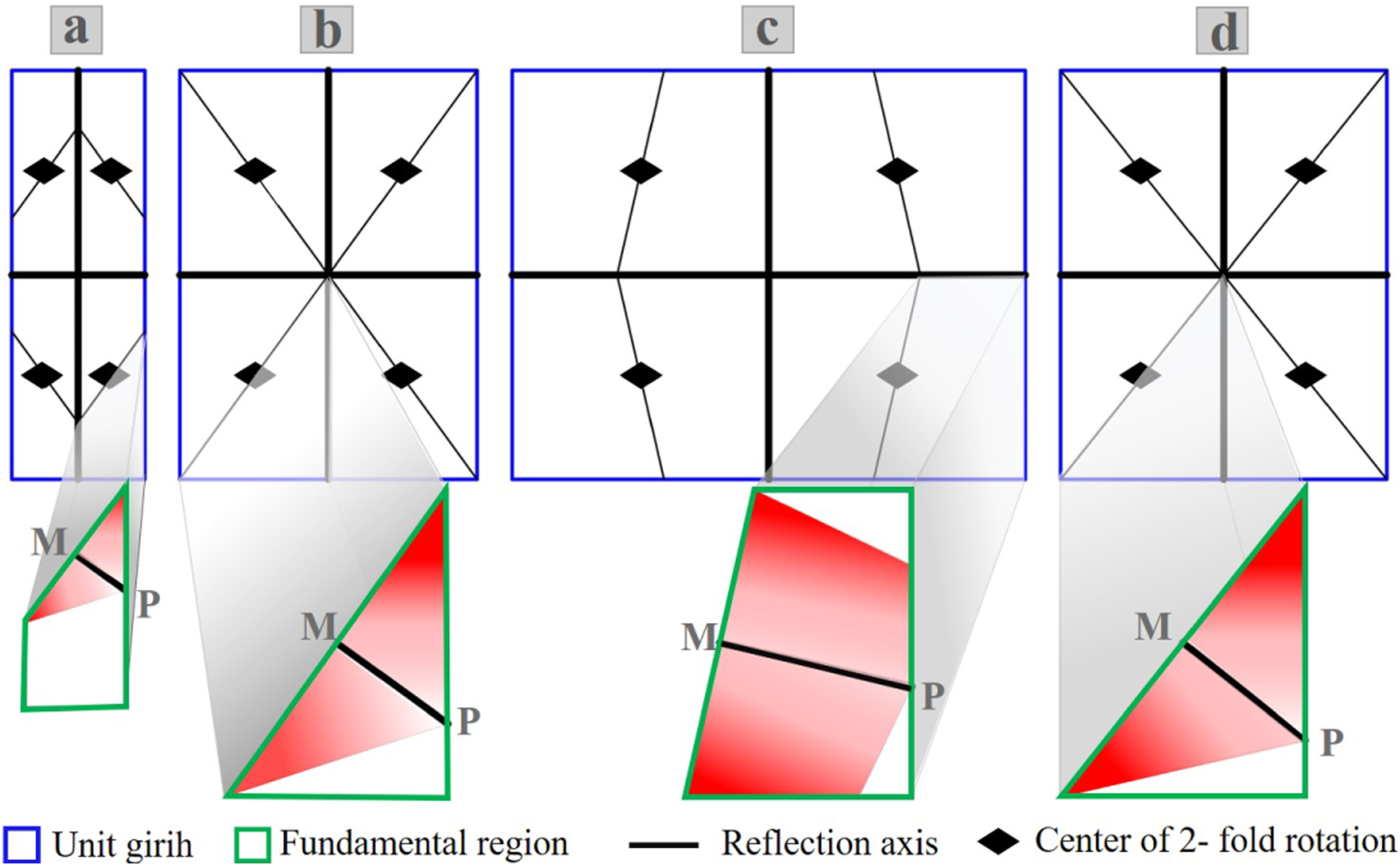
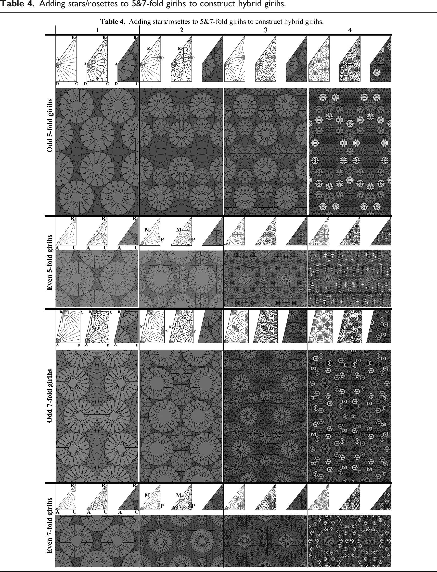

Here, too, it is possible to continue adding 10N-point and 14N-point stars/rosettes within the fundamental region of 5-fold and 7-fold girihs (respectively) among at least three stars/rosettes and generate hybrid girihs with more stars/rosettes (Table 4; this process can be continued ad infinitum).
Results and discussion
In this paper, we have presented a method to generate hybrid girihs. Hybrid girihs are the girihs in which various stars/rosettes, in terms of structure and the number of folds, appear in their final pattern. We first collected historical hybrid girihs from various references; After analyzing them, it was found that these girihs are in two symmetry groups: p6m and p4m, and they are classified into two categories: 2-star/rosette and 3-star/rosette girihs. Based on the analysis (Section 2.1) we present the proposed method of this paper in detail for p4m 3-star/rosette girihs (Figure 19: the blue path). The method, described in Section 3.2, consists of four phases (for 2-star/rosette girihs, it is three phases). We also introduced non-systematic hybrid girihs that can be built using the corridorization and girihs construction process with more steps. Non-systematic hybrid girihs have stars/rosettes centered within and on the boundary of the fundamental region, and we can generate a wide range of these girihs. In general, hybrid girihs can be classified into two categories: systematic hybrid girihs and non-systematic hybrid girihs. Systematic hybrid girihs are classified into p4m and p6m symmetry groups, but non-systematic hybrid girihs can exhibit four symmetry groups: p4m, p6m, cmm, and pmm. Systematic hybrid girihs typically consist of 2-star/rosette and 3-star/rosette girihs, but it is conceivable to encounter 2 to N-star/rosette girihs in non-systematic hybrid girihs (Figure 19). Classification of hybrid girihs.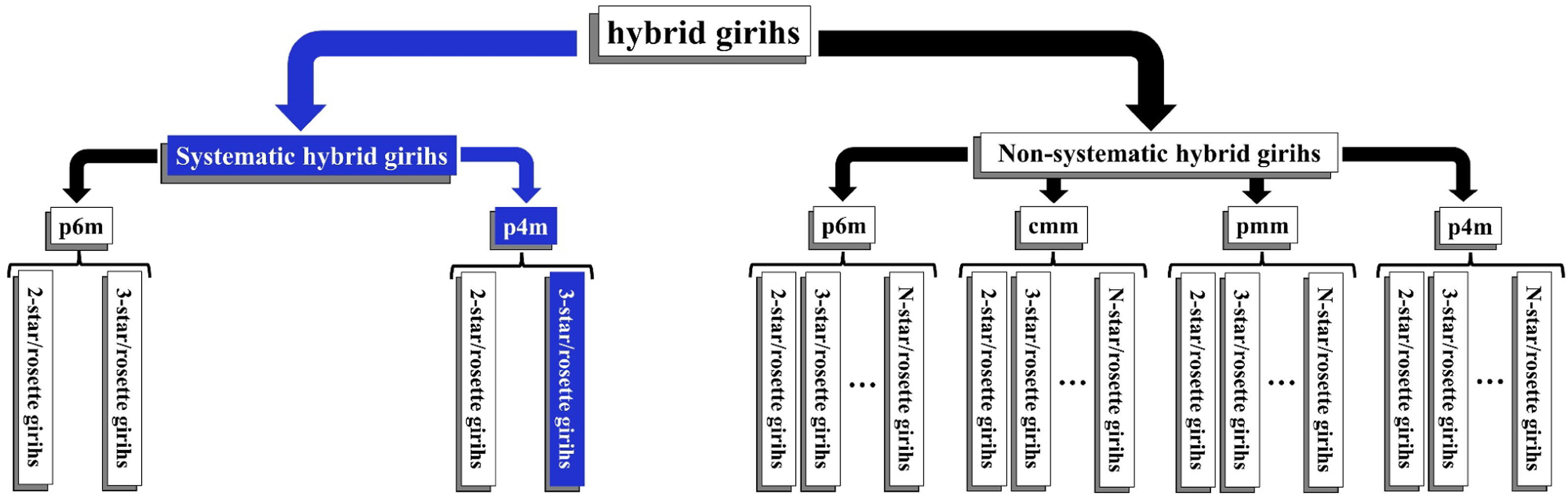
The basis of our work in this paper is the symmetry groups theory. The notation system that shows the generative parameters of girihs (Section 6.1) is a good confirmation of the evolution of our method from 1-star/rosette girihs to 3-star/rosette (hybrid) girihs. Although no specific study has been conducted on hybrid girihs, examples of hybrid girihs can be generated using the PIC method14,29 and the technique outlined by Khamjane and Benslimane.
32
To create hybrid girihs using the pic method, a network of compatible polygons must be established, making it challenging to identify such a network for complex hybrid girihs. Islamic geometric patterns can only be constructed in four families using the pic method: acute, middle, obtuse, and two-point. However, our proposed method can generate numerous patterns that fall between the acute and middle families, for example. In Table 1, girihs 3 and 14 are two-point hybrid girihs that can be constructed using the pic method. However, to cover such patterns with our method, an adjustment in the algorithm is necessary. These patterns emerge when the final segment of line M intersects WH without meeting points W and H (Figure 20; Step 1). To generate these patterns, we extend the last segment of line M (Figure 20; Step 2), perform a mirror reflection of it concerning WH (Figure 20; Step 3), and then construct line Mʹ based on the guidelines in section 5 (Figure 20; Step 4). After the mirror reflections of lines M and Mʹ (Figure 20; Step 5) and the creation of interstitial motifs (Figure 20; Step 6), adjustments are made to the interstitial motifs by adding or removing certain lines (Figure 20; Step 7) until the final pattern is established within the fundamental region (Figure 20; Step 8). If we present the proposed method of this paper according to the two-point girihs, some other girihs, such as girihs 8 and 18 of Tables 1 and in which the last segment of line M (Mʹ) crosses WH (WʹHʹ), and the PIC method does not cover them, cannot be constructed. The process of constructing template motifs of girihs 3 and 14 of Table 1: (a) for girih 14 and (b) for girih 3.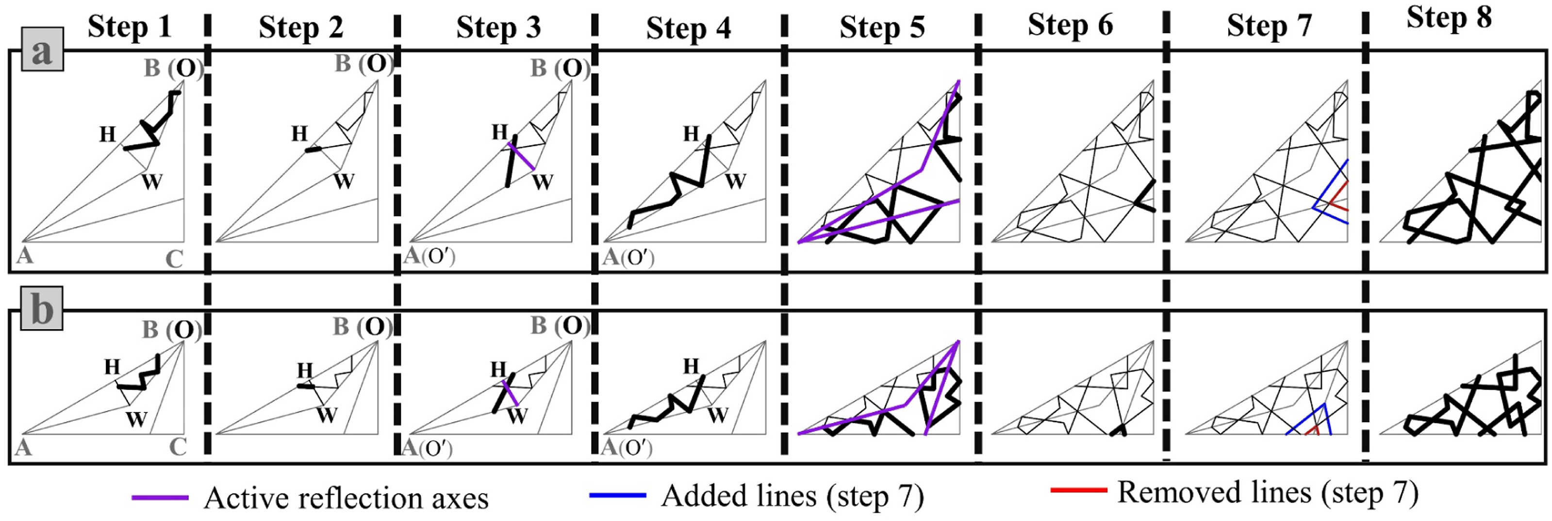
The method presented by Khamjane and Benslimane
32
does not cover two-point girihs and unbloomed rosette patterns. Their proposed method is effective for creating hybrid girihs with adjacent bloomed rosettes. However, when it comes to generating hybrid girihs with non-adjacent rosettes, extra computations are necessary to establish the radius and orientation of the rosettes. For instance, if a rosette is centered around vertex B (Figure 21(a); Step 1), we cannot form a desired rosette around vertex A (Figure 21(a); Step (2) because no correct interstitial motifs are generated, resulting in a proper girih will be not created (Figure 21(a); Step 3). But our proposed method is a step-by-step process, and the created motifs around each vertex help to find the motifs around other vertices within the fundamental region (Figure 21(b)). Therefore, no additional computations are needed to construct such patterns, and it is easier to generate them with our proposed method. How to construct hybrid girihs with non-adjacent rosettes.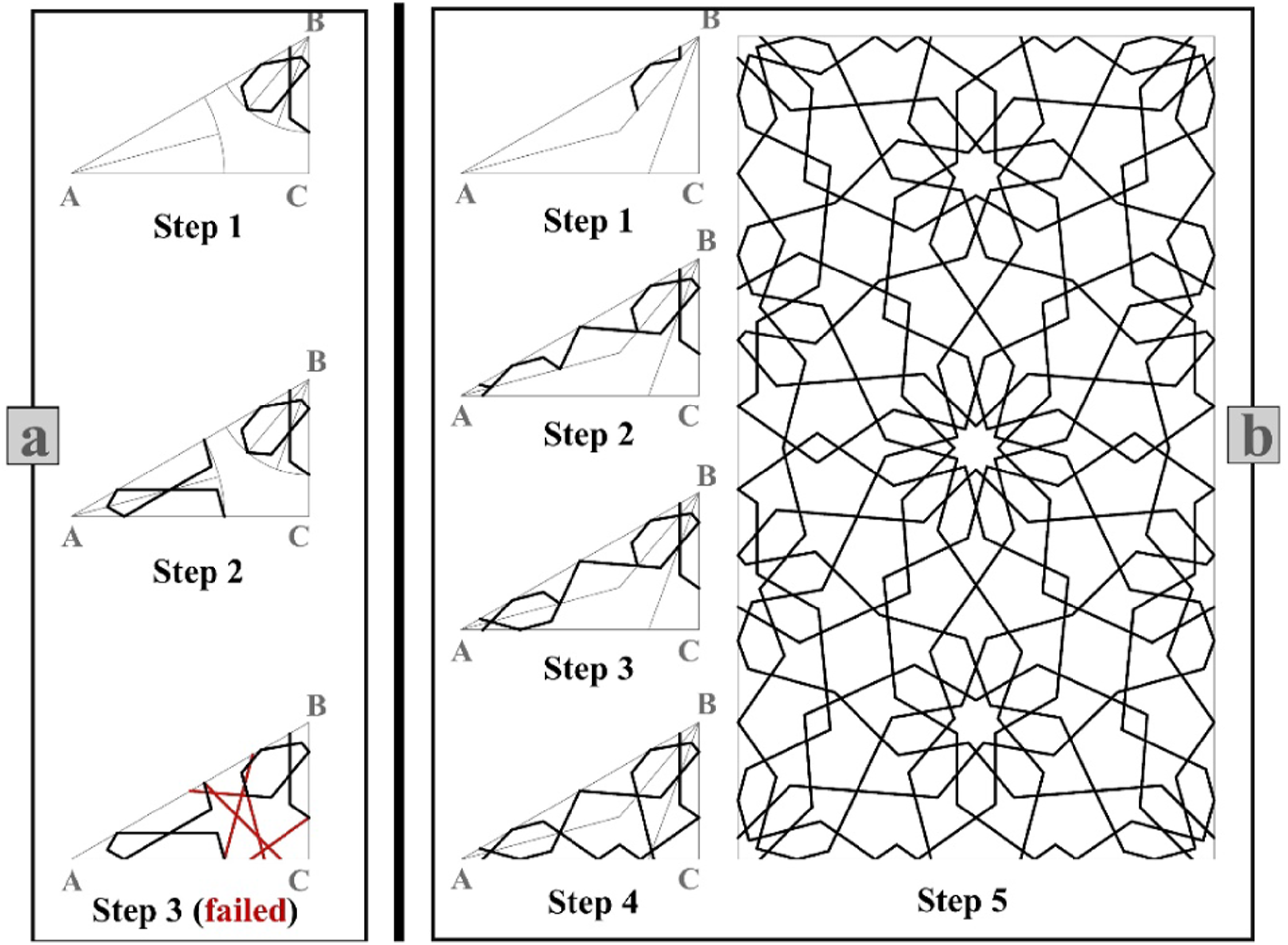
The common symmetry groups in Islamic geometric art are p6m, p4m, cmm, and pmm. 32 Hybrid girihs that are historically authentic and examples of which can be seen in historical buildings and documents are in the p6m and p4m symmetry group. In this paper, we introduced non-systematic hybrid girihs, and based on them, we were able to construct 5&7-fold hybrid girihs, which are categorized into cmm and pmm symmetry groups. Non-systematic hybrid girihs are attractive examples of Islamic geometric patterns, and the step-by-step process of adding stars/rosettes to these girihs (Figures 16 and 17 and Table 4) is reminiscent of seeing more stars in a galaxy or rosettes in a field of flowers.
This paper is the continuation of the process that we have started to decipher and extract the key points and generative parameters of the valuable traditional architecture of Iran to present them in such a way that they can be used in digital spaces and surfaces whose presence in our lives is gradually becoming more serious. Architects will be the content creators of digital spaces and 3D Internet (metaverse). 48 Metaverse content should be dynamic and interactive so that users can interact with and control or edit them. 49 Editing refers to an interactive process that involves changing properties, position, or orientation of objects in the metaverse. 50 Parametrization of the content construction process in the metaverse allows users to do editing. The proposed method of this paper is not only a parametric approach in the construction of content for digital spaces but also a parametric approach in motif construction to adorn the physical elements of buildings.
Conclusion
This paper describes a mathematical analysis of historical hybrid girihs (historical hybrid Islamic geometric patterns) to present a parametric and digital method for generating the classical and a wide range of novel girihs. The method can yield patterns that would not be achievable using the previous approaches.
Parameterization and discovery of generative parameters in the proposed method of this paper is such that users and designers can change the generative parameters for handling and controlling the final patterns of girihs based on their aesthetic judgment and can see visual changes resulting from changes in parameters on digital platforms and screens. The ability to adjust generative parameters and witness the visual impact of these changes opens up new possibilities for artistic expression and creativity within Islamic geometric patterns. By incorporating user input and aesthetic judgment, the method empowers individuals to create unique and personalized designs that reflect their cultural and artistic preferences. This approach opens up new possibilities for the application of Islamic geometric patterns in various design contexts, from architectural elements to decorative objects, and provides a bridge between traditional craftsmanship and modern digital fabrication techniques. We hope this paper inspires further exploration and innovation in girihs, paving the way for a new era of hybrid Islamic geometric design.
Footnotes
Author’s note
This article is based on the doctoral thesis of the first author, which is being conducted by Dr Abdulhamid Ghanbaran in Dept. of Architecture and Urban Planning, Shahid Rajaee Teacher Training University, Iran.
Declaration of conflicting interests
The author(s) declared no potential conflicts of interest with respect to the research, authorship, and/or publication of this article.
Funding
The author(s) received no financial support for the research, authorship, and/or publication of this article.
Data availability statement
No data was used for the research described in the article.