
Abstract
This paper studies the development of a semi-automated process for designing and fabricating node-based lattice spatial structures using bamboo as an ecological material. The study addresses the challenges of integrating bamboo—a naturally variable material—into spatial structures and was conducted through a hybrid workshop at the Digital Craft House, University of Art, Tehran, during COVID-19. Traditional CAD tools are often limited when applied to non-industrialized, organic materials like bamboo. This research introduces a tailored computational workflow and a semi-automated fabrication apparatus explicitly designed to create complex, freeform bamboo structures. Combining online and in-person sessions allowed participants to engage with both the theoretical and practical aspects of the design-to-fabrication process. This approach enabled the continuous development and refinement of custom tools and methods during COVID. The workshop showcased how synthesizing advanced computational approaches and natural materials could trigger new architectural solutions and autonomy by developing a single-layer, freeform spatial structure, promoting ecological and advanced architectural practices.
Introduction
This paper presents a workshop focused on developing an integrated computational design, digital fabrication process and bespoke tools to create a single-layer freeform spatial structure using bamboo. The workshop emphasized the role of computation as a mediator between design intent and the geometric logic of material utilization and fabrication processes. This approach aims to bridge the gap between design’s formal and operational aspects, particularly when working with complex geometries and materials such as bamboo.
Recognizing the growing demand for computational design skills and technology integration, incorporating these into educational frameworks enables designers and architects to gain tailored knowledge and hands-on experience. 1 To address this need, Dahi Studio 1 initiated its Freeform Spatial Structures (FSS) academic workshops in 2019 at the Digital Craft House (DCH) 2 of the University of Art, Tehran. In this series of workshops, students learned the basics of computational design and digital fabrication and investigated the potential of various materials and structural systems. Through hands-on experience, students developed spatial freeform building systems, built prototypes to explore design and fabrication methods, and finally implemented them in the computational design and fabrication workflow by building 1:1 scale structure.
Freeform spatial structures were selected as the workshop’s main topic because they are nonstandard structures that can include multiple unique and customized elements. This choice allows students to face challenges related to the structural system, form-finding approach, fabrication, and assembly, while exploring potential solutions using a computational problem-solving mindset.
2
These complex forms, streamlined through computational design and digital fabrication (CDDF), offer a proper platform for developing expertise in computational design and hands-on construction experience. Hands-on experience, including working with the material to understand new logics, prototyping, digital fabrication of the elements, and final construction assembly, is the most important part of this workshop, which was impacted by the effects of COVID-19. Following three successful experiences in 2019 and 2020 before the pandemic (Figure 1), the workshop team redefined the process to align it with the pandemic conditions. This involved incorporating virtual components, reducing in-person sessions, and limiting physical presence. Despite concerns about less hands-on experience, virtual sessions and access to instructors and experts from international institutions were expected to greatly benefit the students. Final structure of FSS workshops 1, 2, and 3 from left to right.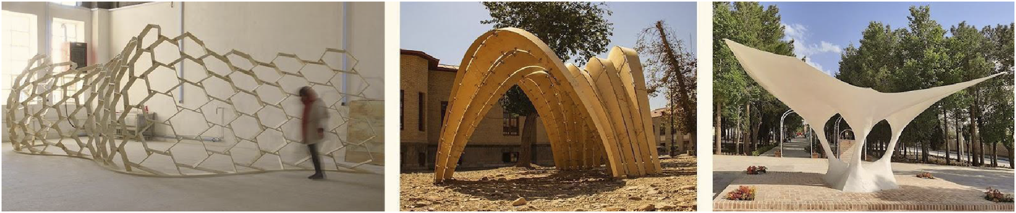
Bamboo was selected for experimentation due to its potential to fulfill the tubular geometry suitable for the spatial structure. As a rapidly renewable material known for its short harvesting cycle and ability to absorb carbon dioxide, bamboo possesses a unique structural form.3,4 Its tubular shape and the reinforcing rings along its length orient the fibers longitudinally, contributing to an excellent strength-to-weight ratio. These characteristics make bamboo a suitable alternative to more energy-intensive materials in constructions such as space frame structures, where loads are predominantly transferred axially.5–8
Despite its use in certain regions, research projects, and vernacular settings, bamboo’s full potential in freeform structures requires further investigation due to its natural variability and the limitations of existing connection systems.5,9,10 One of the main challenges in bamboo structural systems is the connectors, leading most research to focus on joinery systems and connection methods. The variability of unprocessed bamboo poles and the specificity of traditional connection systems designed for materials like metal or timber pose significant challenges, often restricting the geometric configurations and complexity achievable with bamboo.
Research has identified limitations in digital modeling for predicting bamboo’s behavior in architectural-scale structures using traditional weaving techniques. 10 To address these challenges, various studies have focused on enhancing traditional bamboo connections and developing engineered bamboo materials through advanced techniques, emphasizing digital integration into the design-to-fabrication workflow. 12 Furthermore, the lack of building codes and limited information on using bamboo as a structural material, particularly for bending-active applications, posed significant challenges, with most references limited to general bamboo architecture. 13 Despite these challenges, attempts have been made to optimize active-bending structures through advanced simulations and design models.14,15 Similarly, A study on a hybrid bamboo dome showcases bamboo’s potential in space structures, utilizing active bending beams, tensile grids, and hinged lashed connections with optimized textile joints and composite bandages for enhanced structural integrity. 16 Technologies like 3D-printed joints have also been explored to facilitate the design and fabrication of bamboo structures. 17
This research builds upon these precedents by integrating bamboo as a biomaterial into a tailored design and fabrication workflow for a single-layer spatial structure. CAD tools have expanded design exploration by leveraging computational methods, providing designers with broader methodologies for a fabrication-aware design, and generating fabrication information. 18 These tools, along with simulation technologies, enable the exploration of new knowledge areas using customized design tools, allowing the analysis and integration of various data types to develop and evaluate ideas from multiple perspectives, thereby aiding more informed decision-making.19,20 However, current CAD tools still face limitations in integrating design and fabrication complexity with the variability of natural materials and different structural systems. The research responds to these challenges by developing a workflow that harmonizes bamboo’s inherent properties with computational design and digital fabrication, contributing to broader architectural engagements with ecological systems. By utilizing natural materials in the computational design process, the study advances materiality and performance in construction, challenging the conventional boundaries between the natural and the artificial in architectural practice.
Methods
This research aims to develop a workflow through computational design and digital fabrication to create a single-layer freeform spatial structure using bamboo as a biological material. The workshop, designed as a practical training ground for students, was structured into four main stages: 1) study, 2) design, 3) fabrication, and 4) assembly.
The initial study stage was dedicated to examining existing precedents to understand the approaches taken by other researchers concerning our inquiry. The literature review was categorized into three primary areas: a) materiality, b) structural system, and c) design methodology. The design stage involved two interconnected tasks: system design and form design. Utilizing bamboo with non-standard shapes in a freeform structure presented several challenges, as each node had a unique shape, requiring computational design and digital fabrication techniques to create a diverse array of nodes. Moreover, these nodes needed to bear bending moments effectively to ensure stability and load-bearing capacity. Using a double-curved surface for the single-layer structure makes more efficient exploitation of the geometrical form possible, which greatly improves the overall stiffness of the structure and reduces induced stresses. The design, particularly the building system, also needed to be adaptable to accommodate the varying sizes and shapes of the bamboo.
To address the mentioned challenges, the building system (nodes) was designed to accommodate the diverse shapes of bamboo, ensuring that variations in size did not compromise structural integrity. The joints were engineered to carry bending moments. A computational design workflow in Rhino -Grasshopper generated a parametric BIM model that included all necessary fabrication data for the precise fabrication of elements and joints. The final form of the structure was derived through an equilibrium-based form-finding process optimized for self-weight as the dominant load case using Karamba3D. The elements were fabricated using a custom rotary apparatus, adapted for the axial angle differences between connections, following multi-plane nodal analysis. The next section details how this method was implemented through a case study in the context of a workshop.
Development and case study
The context
The workshop was designed as a 12-week hands-on hybrid summer program for 40 to 50 students during COVID-19 in 2021, guided by a team of 11 architects and engineers, including eight national and three international instructors. The program emphasized active participation and research engagement, structured around key milestones and topics while remaining flexible for diverse student groups. Each week featured a four-hour core session, supplemented by smaller group troubleshooting and revision meetings, with instructors assigning tasks for students to complete throughout the week (Figure 2). Due to the pandemic, the workshop was conducted in a hybrid format. Students and instructors collaborated online for research and design and met in person for prototyping and assembly. Workshop timeline agenda, outlining stages and tasks for each phase, including study, design, fabrication preparation, and construction.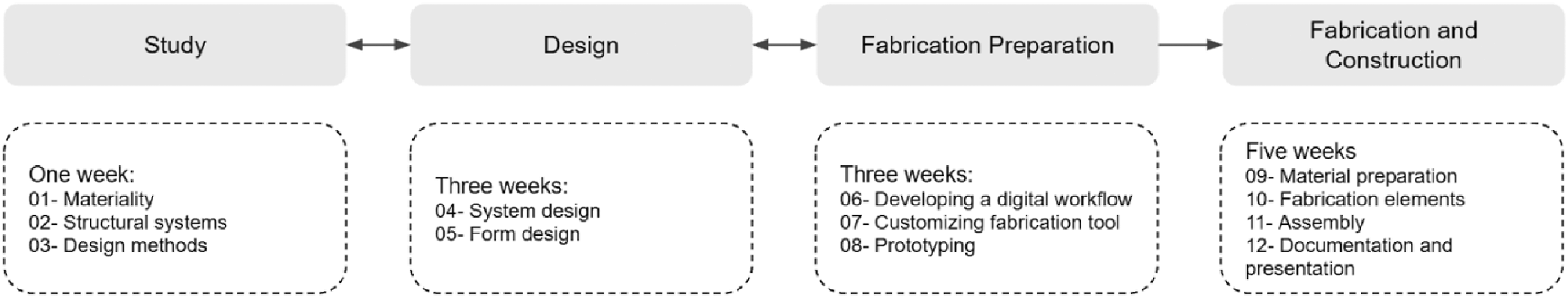
Tools and framework development
Stage one: Study
During this stage, students were divided into three groups to focus on key topics: material exploration, structural system design, and form-finding methods. The virtual setting facilitated collaboration between students and instructors from Virginia Tech, the Tehran University of Art, and Surrey University, encouraging discussions on bamboo’s potential, challenges, and techniques for creating freeform spatial structures using computational methods. The first group researched bamboo as a structural material, including relevant building codes and local material options for the workshop (Figure 3). The identified bamboo type available in Iran, Kheizaran (Bambusa vulgaris), meets the LEED v4.1 criteria for sourcing local material within 100 miles.
21
This bamboo exhibits excellent mechanical properties, including compressive strength exceeding 60 MPa and tensile strength over 100 MPa, with tensile strength recorded at over 200 MPa across all parts of the bamboo.22,23 Material Studies; (A,B) internal structure of the bamboo, (C) dimensional measurements (D) study of the internal structure of the bamboo (E) rough estimation of bending strength (F) perforation tests on bamboo.
The second group studied and documented different structural system designs and presented the advantages and challenges of each for spatial structures. The third group explored form-finding methods, presenting an overview, sample projects, relevant software, and tools, along with methods and Grasshopper codes for experimentation. These methods included graphic statics, the force density method, dynamic relaxation, and layout optimization.24–28 The chosen platforms for integrated design tasks were Rhino version 7 and Grasshopper, which were presented and documented during course sessions,29,30
Stage two: Structural system design
In this phase, which involved structural system and form design, students were also introduced to digital fabrication techniques and tools, gaining familiarity with standard devices, robotic arms, CNC machines, 3D printers, building custom devices, and programming with microprocessors like Arduino through lectures and presentations. Using this knowledge, they proposed diverse joinery systems for bamboo lattice spatial structures during brainstorming sessions, selecting candidates based on system performance. Explorations included alternative joint designs, such as the nodal system, reciprocal frame, and bending active system, using materials like plywood and steel with CNC routers and laser cutters. The fabrication laboratory. team presented prototypes of the selected designs, providing participants with hands-on fabrication experience (Figure 4). These prototypes were evaluated for performance, cost-effectiveness, and aesthetics, helping to inform design selection. Prototyping different design alternatives: (A) star-like steel connection (B) reciprocal connection (C) polyhedron steel connection (D) star-like plywood connection option 1 (E) star-like plywood connection option 2.
Among the precedent studies reviewed by the students, most with minimal design intervention primarily focused on tying bamboo poles together using various fasteners or bands, like traditional bamboo construction methods. Others involved bending long bamboo pieces for active bending techniques. However, we eliminated active bending options due to the limited length of available bamboo types. Consequently, we opted for a node-based or a nexorade structure, which required an intermediary piece to be attached to the bamboo. Based on our tests, we determined that drilling was the least invasive method, as it prevented fraying, maintained strength, and allowed for the attachment of an intermediary piece. This approach was chosen to adapt the design solution to the inherent properties of bamboo, ensuring structural integrity while accommodating the material’s natural characteristics. The final joint detail was designed to be adaptable to various bamboo diameters, ensuring the joint fits within the bamboo.
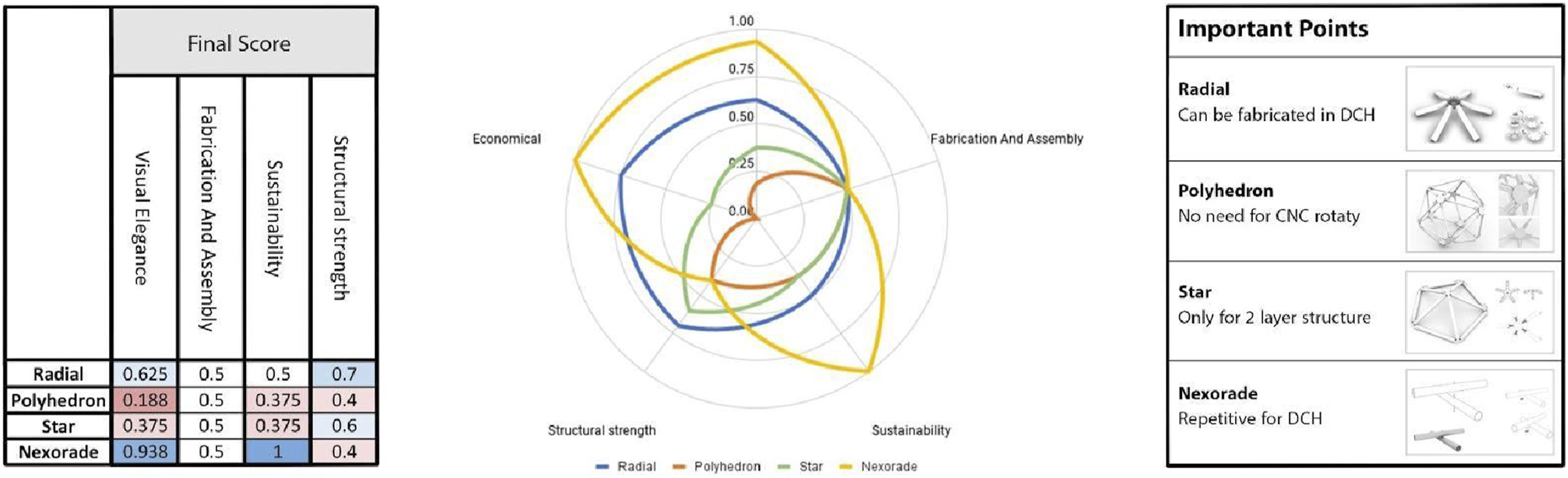
Figure 5 presents criteria grouped into five categories and sub-categories, graded according to their studied conditions, with final assessments applied. The ultimate choice was influenced by both criteria evaluation and students’ preferability (Figure 5). Although the reciprocal system received a higher grade, the radial system was ultimately chosen after discussions between instructors and students, who favored the opportunity to explore a new node design (Figure 6). Consequently, some extensive design iterations were made on the final node alternative to make its fabrication simpler and achieve a faster assembly time (Figure 7). The evaluation criteria and assessment of each alternative. Number 1 in the legend indicates the high point, and 0 indicates the low point. The evaluation process to determine suitable joinery design alternatives. Final node design, a U-shaped screw has been added to make a simpler connection between the node and handle.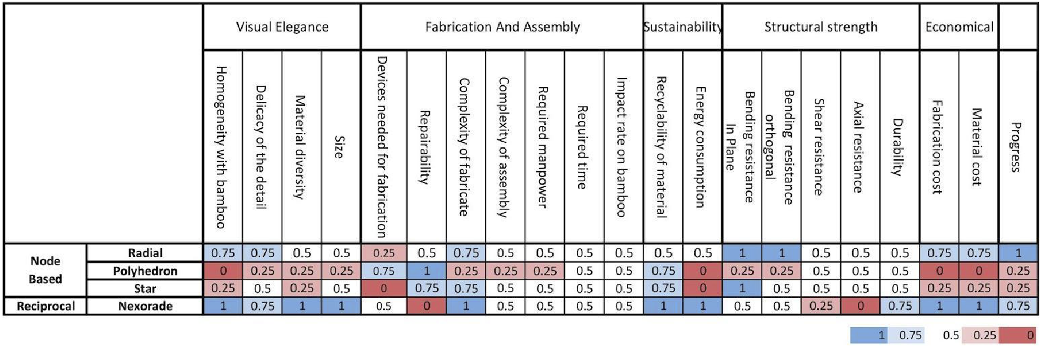
Students used hand sketching, physical prototyping, and digital design during the form design process, resulting in 13 shortlisted designs (Figure 8). These were evaluated in class discussions based on support conditions, curvature, element count, novelty, and spatial qualities with participants and instructors voting to select the final form based on preferred experiences. An initial structural analysis was performed, then forces and deformations were assessed. The selected design, intended as a 60-square-meter campus resting space, was developed using Rhino Grasshopper for form-finding. Final design alternatives.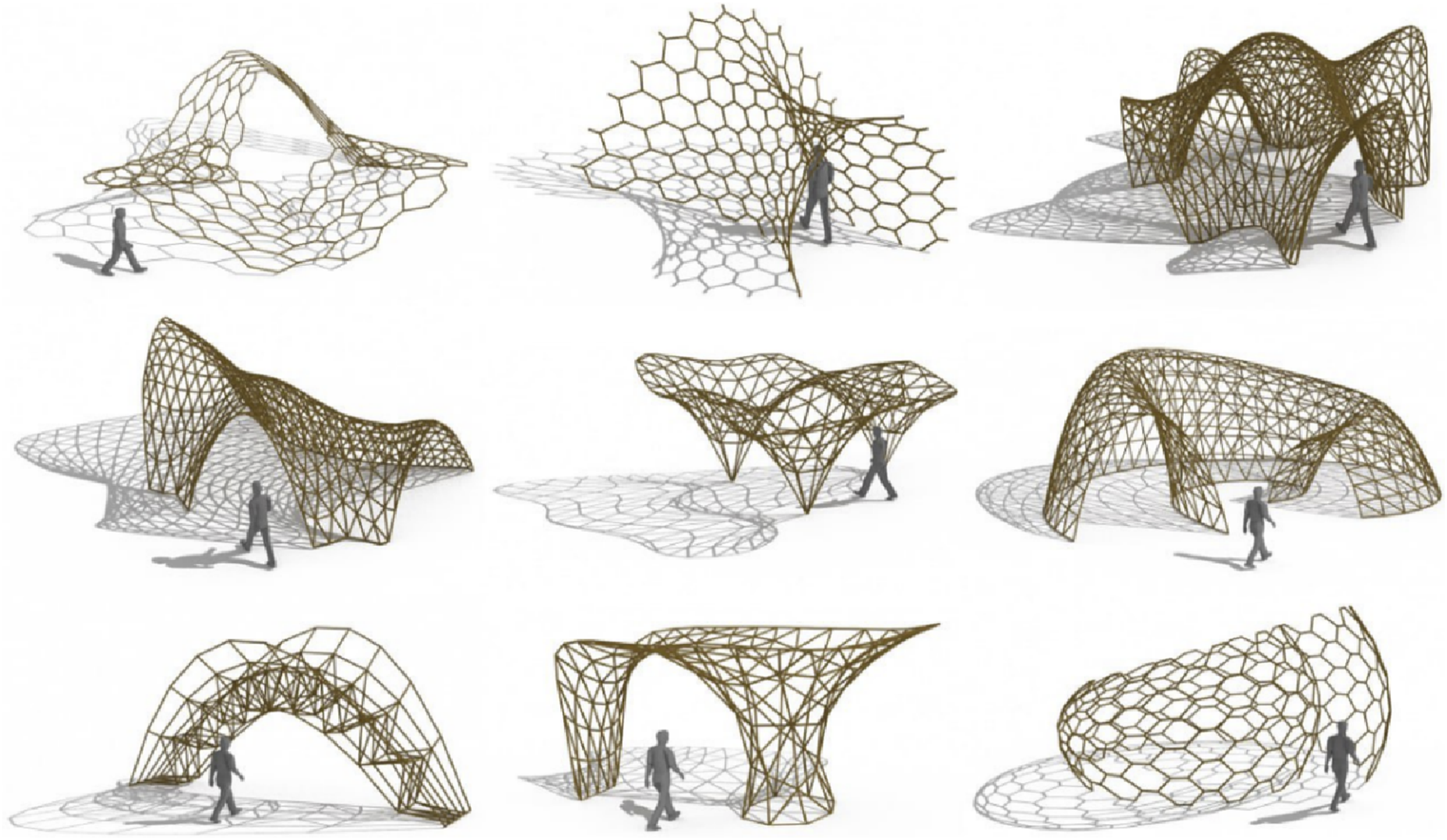
Stage three: Fabrication preparation
Structural analysis
Following the form design phase, structural assessments were conducted using Karamba3D and SAP2000 to analyze forces and displacements. Due to its single-layer configuration, the stiffness and stability of the structure are influenced by the stiffness of the nodes. Therefore, a sensitivity analysis was performed to evaluate how variations in node stiffness affect internal forces and displacements (Figure 9). (A) Illustrates tensile and compressive forces in the members under gravitational loads assuming rigid nodal connections. (B) Demonstrates the sensitivity analysis of maximum compression and displacement in the structure with respect to the node stiffness, providing insight into the importance of node rigidity in the stability of the single-layer structure.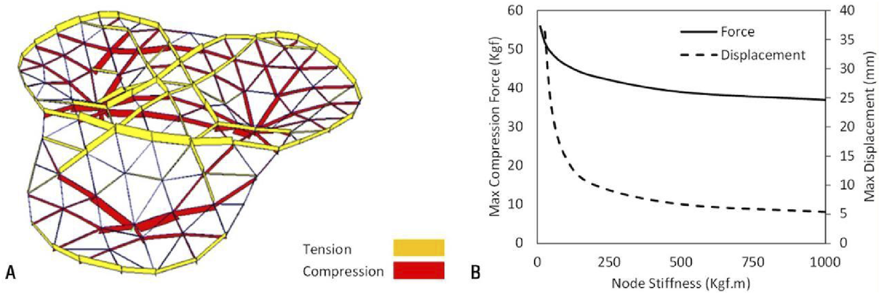
BIM tool
To enhance the design-to-fabrication process and address the complexities of modeling freeform structures, a parametric 3D BIM model was developed. This model was used to evaluate structural details, determine optimal node size and orientation in 3D space, and extract fabrication and assembly data while addressing the uniqueness of each element’s shape (Figure 10). The digital design workflow began with inputs from the user, including a wire mesh from form design and numerical values for bamboo culms, CNC machines, screws, and node design preferences. These inputs were processed to generate a detailed 3D model with element tags, facilitating assembly coordination. The workflow comprised input reception, preliminary data preparation, 3D geometry generation, coordination model preparation, clash detection, shop data generation, and BIM estimations and statistics (Figure 11). Challenges with modeling a freeform structure: determining the optimal node size and orientation in 3D space (A) too large node, (B)too small node, (C)optimum node size, (D)too low elevation, (E)too high elevation, (F)optimum node elevation. The BIM workflow: An overview of the Grasshopper script.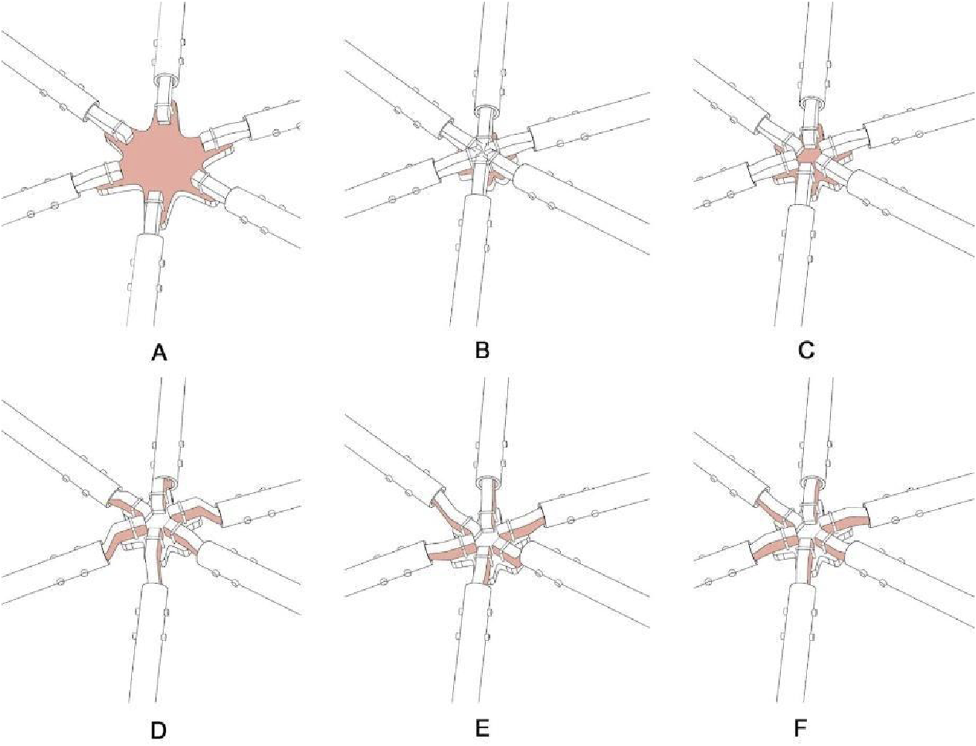
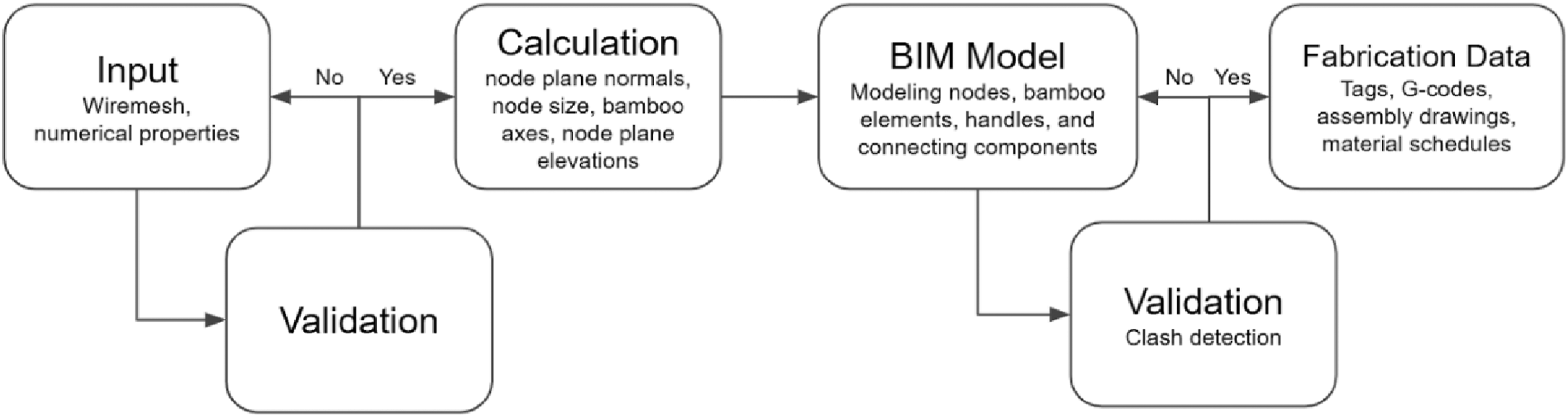
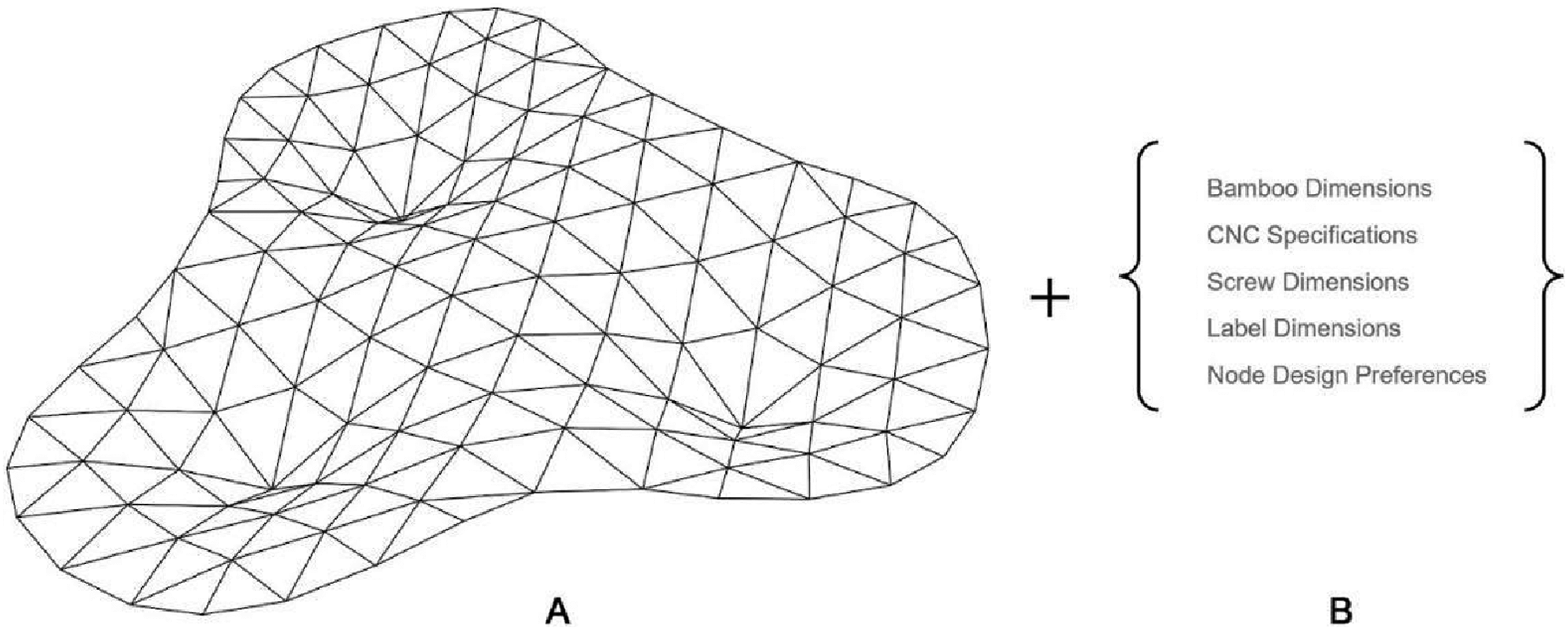
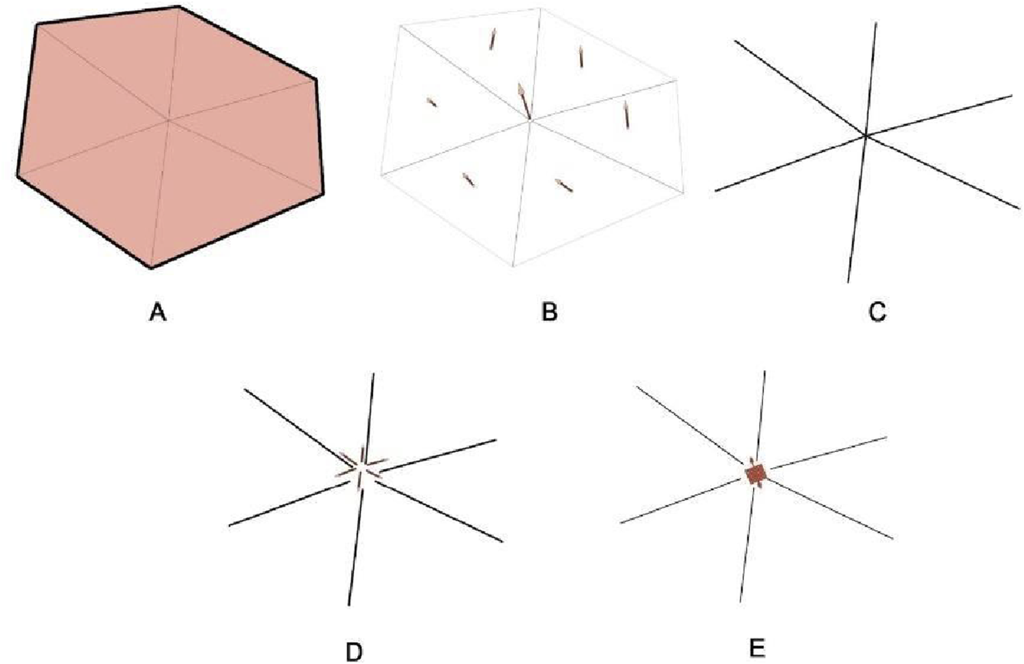
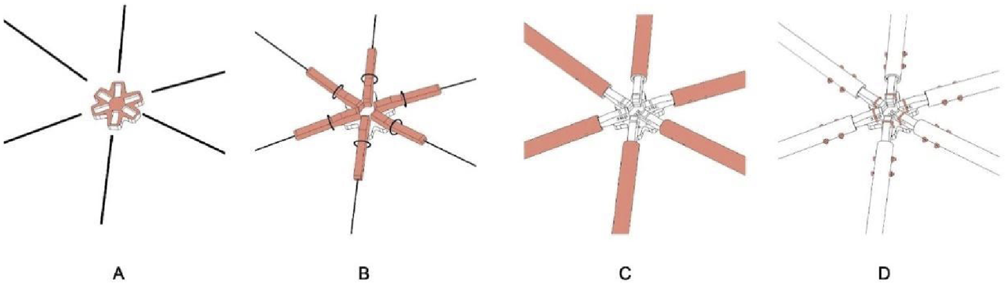
Steps of the script: a) The workflow begins with user inputs, as shown in Figure 12: geometric (base wire mesh for nodes and beams) and numerical (CNC details, bamboo radius, etc.). The code validates data, alerts of issues like mesh problems, and prompts revisions if necessary. b) The code processes inputs, calculates key preliminary data, determines node normal planes and node sizes to prevent clashes, trims edges for bamboo axes, and computes node plane elevations using the average elevations of bamboo element endpoints (Figure 13). c) based on preliminary data, the geometrical modeling process includes four main steps, starting with generating 2D boundary curves and concluding with a 3D model at Level of Detail (LOD) 400. These steps involve modeling nodes, bamboo elements, handles, and connecting components using specified parameters such as size, axes, and screw details (Figure 14). d) For assembly coordination, unique identification tags are assigned to nodes, handles, and bamboo elements (Figure 15). These tags, engraved during milling, are integrated into a 3D coordination model to facilitate efficient positioning and identifying the correct parts, streamlining the assembly process. e) After preparing the geometrical model, clash detection algorithms identify issues like self-intersections and handle-bamboo conflicts. If clashes occur, the code stops and alerts the user, prompting necessary revisions. f) Following the production of a clash-free 3D model, users can optionally generate shop data, which includes plywood sheet layouts for CNC milling of the nodes and handles and necessary data for cutting and drilling bamboo elements, like culm length, hole positions, angles, and tags (Figure 16). g) The code also provided fabrication estimates and statistics for design comparison and material takeoff which included 3 plywood sheets, 314 bamboo culms, and 116 nodes (Figure 17). The average bamboo length was 738 mm. The main inputs of the code include (A) a wire mesh as the main geometrical input and (B) numerical inputs and specifications. The steps of preparing the preliminary data for further geometrical modeling (A) initial mesh, (B) node’s normal (average of neighbor face normal), (C) extracting bamboo axes, (D) trimming bamboo axes (based on node’s size), (E) adjusting node’s plane elevation. The steps of generating the geometrical model of the nodes, handles, bamboo elements, and screws. (A) Generating 3D nodes, (B) generating 3D handles and subtracting holes, (C) adding schematic bamboo poles, (D) adding screws, nuts, and washers. Assigning ID tags and labels to each node, handle, and bamboo element. (A) Adding node’s tag and pockets’ Tags (counterclockwise order), (B) adding handles’ tags (based on node and pockets’ tags), (C) adding bamboo tags (based on handles’ tags). Example of generated shop data of nodes, handles, and bamboo culms. Numerical estimations and statistics generated from the parametric BIM model.
Developing tailored rotary apparatus
During the fabrication process, a significant challenge was to connect each bamboo pole at both ends to respective joints using two pairs of screws. These screws were not parallel within the pole’s section plane, and the angles between their axes varied from less than one degree to over 15 degrees. This complexity required an innovative solution that exceeded the capabilities of the existing 3-axis CNC router machine, which was limited to vertical drilling (Figure 18). To address the multi-plane nodal condition, a customized rotary tool was developed from scratch. This initiative not only overcame the challenge, ensuring the successful fabrication of the final product, but also provided a valuable practical exercise in digital fabrication for the students involved. By tailoring and refining custom tools through continuous evaluation and adjustment, students engaged directly in iterating design solutions, enhancing their ability to reframe and address complex design problems. The required rotary mechanism to accommodate the axial angle difference between two pairs of bamboo holes and the variation of their lengths.
The tool’s chassis, carefully designed in Rhino, was crafted from 18-mm-thick plywood. This design included a secure gripper on one end and a movable cone-shaped fixture on the other, which could slide along a rail system to accommodate bamboo poles of varying lengths. The cone’s design was pivotal, ensuring minimal deviation of the pole’s axis from the rotational axis during the drilling process (Figure 19). The rail, wagon, and rotator of the custom rotary tool were assembled and fixed on the three-axis CNC router machine’s worktable.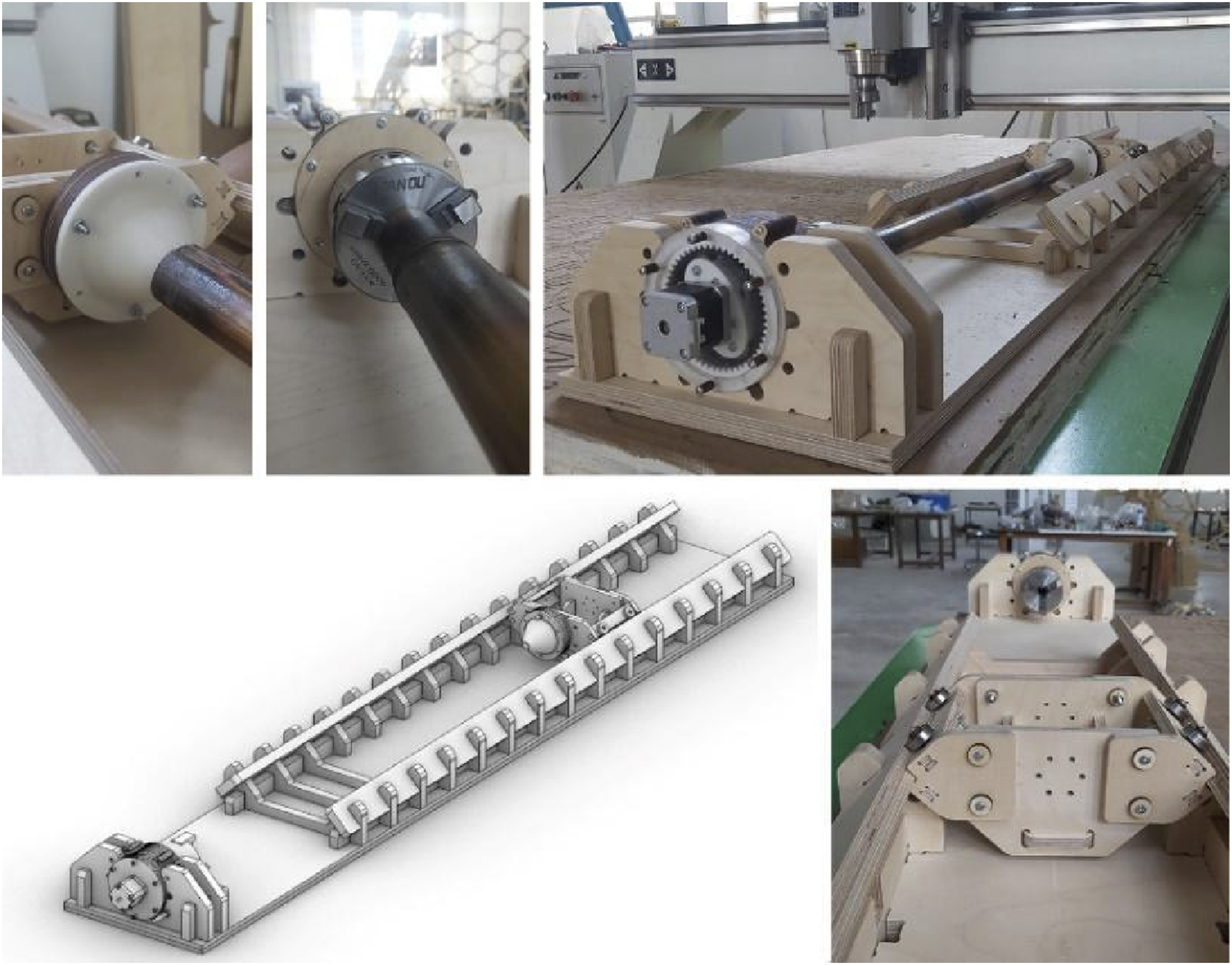
A key component of the tool was the rotation mechanism to which the gripper was attached. After evaluating various options, including planetary gears, pulley systems, and harmonic drives, the harmonic drive was selected for its superior precision. This harmonic drive was carefully engineered from laser-cut 3-mm plywood and plexiglass reinforced with slender screws. This assembly included solid and flexible 3D-printed components made from polylactic acid (PLA) and thermoplastic polyurethane (TPU) materials, along with ball bearings and a stepper motor (Figure 20). Fabricating the harmonic drive, (A) internal components of the harmonic drive, (B) harmonic drive assembly, (C) harmonic drive exploded view, (D) solid part made out of PLA and flexible part made out of TPU.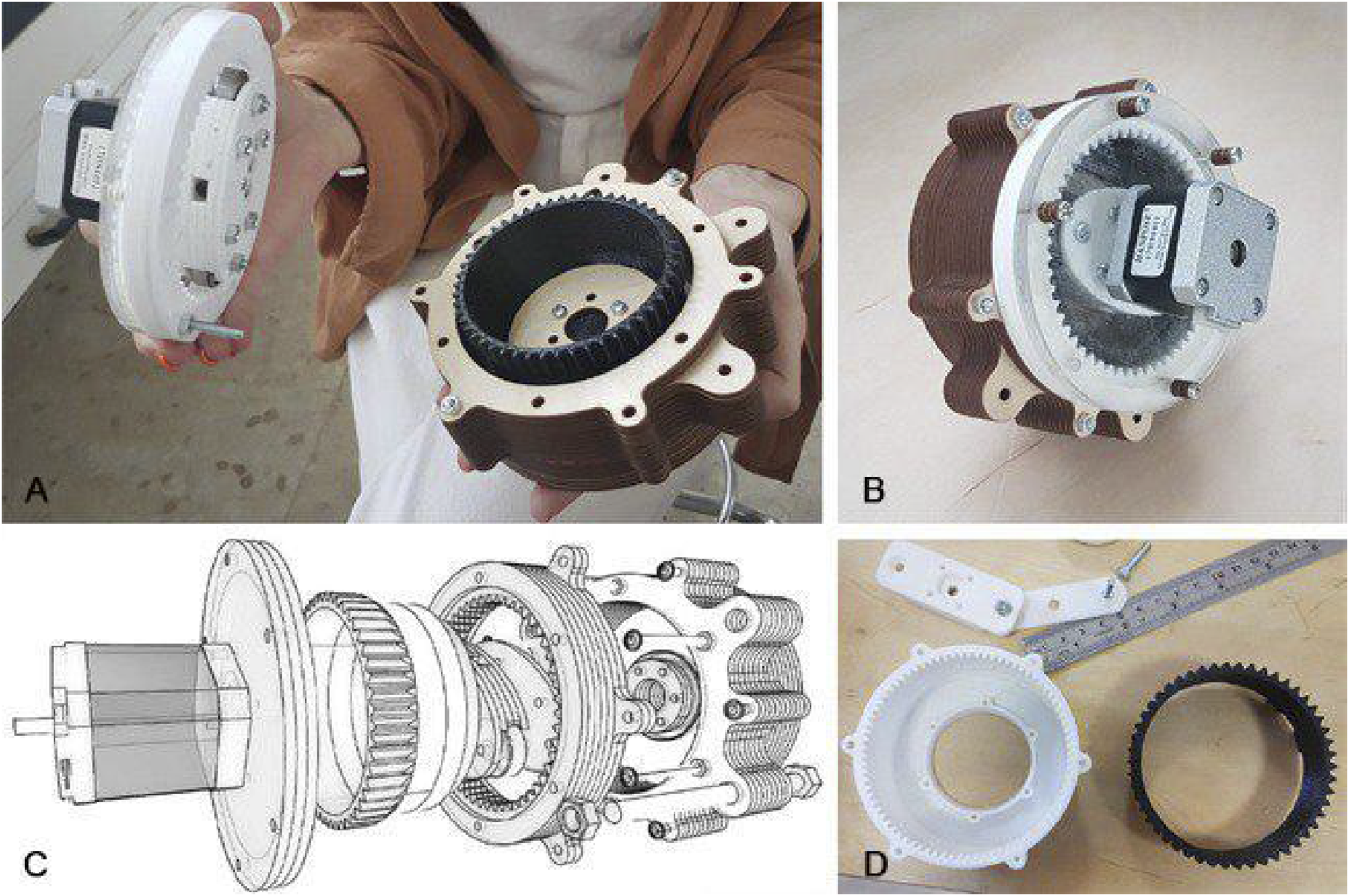
An Arduino Mega was integrated to control the stepper motor within the harmonic drive, enabling precise rotation to the desired angle. Complementing this setup, a specialized algorithm was developed in Grasshopper. This algorithm interpreted rotation angles for each bamboo pole directly from the BIM file, thereby generating the necessary programming for the microprocessor. The fabrication of this custom-made tool not only solved a complex engineering problem but also provided a hands-on learning experience for students, bridging the gap between theoretical knowledge and practical application in digital fabrication.
The bamboo drilling process involved two main components: developing an Arduino program and preparing a CNC file for machine movement based on BIM file data. The critical data included the axial rotation angle for each bamboo piece. The Arduino program was developed to rotate the bamboo poles to the required angle using a stepper motor, with the rotation angle set as a variable so that the specific angle for each element could be easily replaced. A Grasshopper algorithm was created to read the Arduino template and generate a customized program for each bamboo pole, which was then uploaded to the board via a USB-connected harmonic drive. The board was manually restarted to execute the program, ensuring correct rotation.
The CNC process depended on the lengths of the bamboo poles. An algorithm was developed in Grasshopper to simulate the CNC router toolpath, determine path key point positions, generate XYZ outputs, and generate the G-code for the CNC machine. The toolpath simulation demonstrated how the machine moved from the home position to a specific height, reached the bamboo’s lower end, performed two vertical movements to drill the holes, then moved along the Y-axis based on the bamboo’s length, performed two more vertical movements to drill the final holes, and finally returned to the starting point. The length variable in the G-code template was automatically adjusted based on the BIM file for each bamboo, named accordingly, and exported to be run later along with the previously mentioned Arduino program. The vertical drilling of the CNC router machine, coupled with the axial rotation derived from the rotary rig, resulted in having all the elements of the spatial structure ready for the assembly stage. Although the drilling process was based on the BIM file, manual verification of the hole positions and the angle between the holes at both ends was still necessary to ensure accuracy, with the potential for human error being mitigated through post-process checks.
Stage Four: Construction
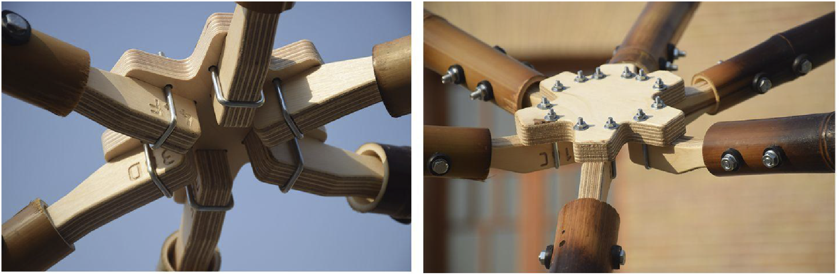
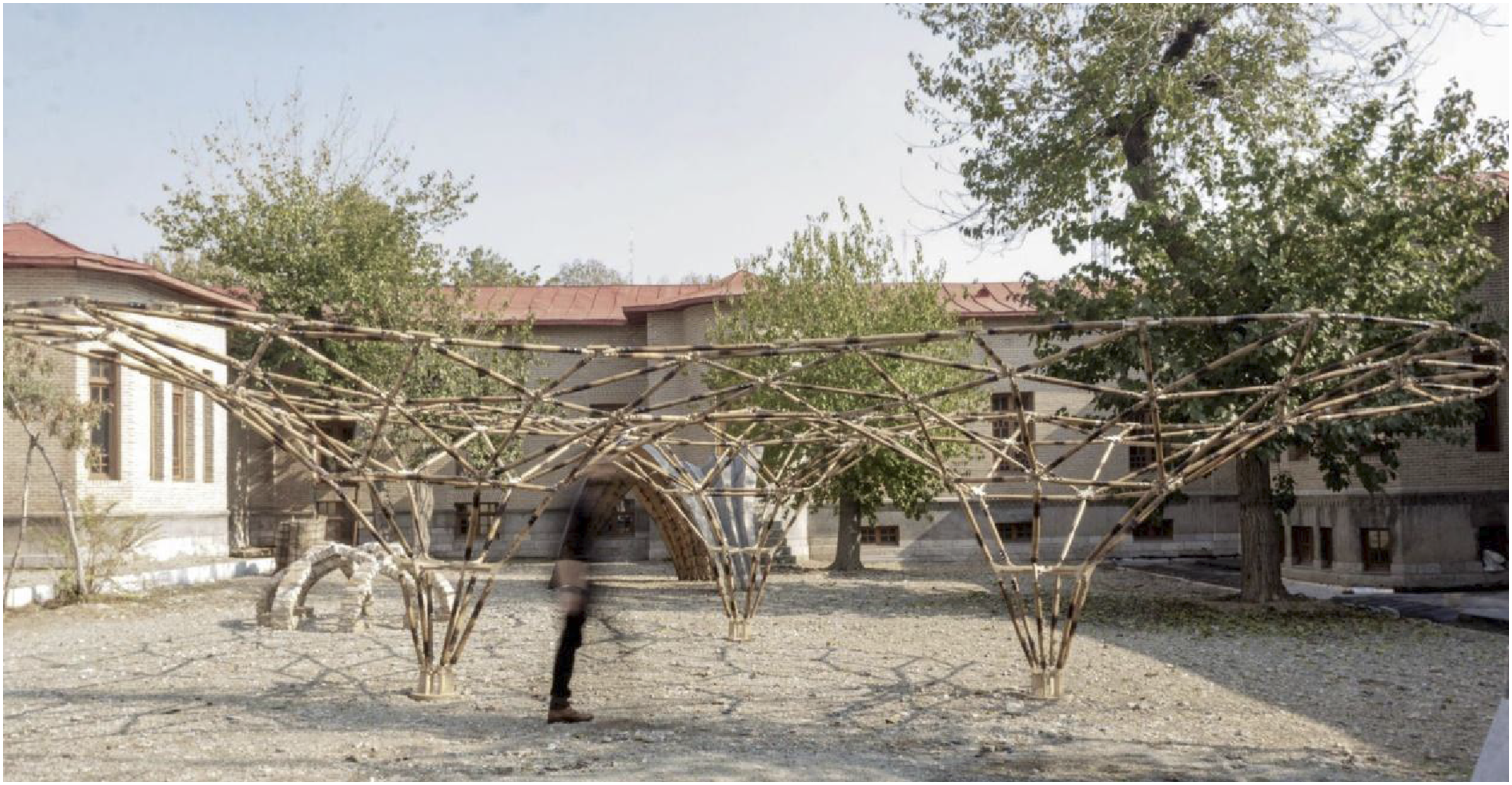
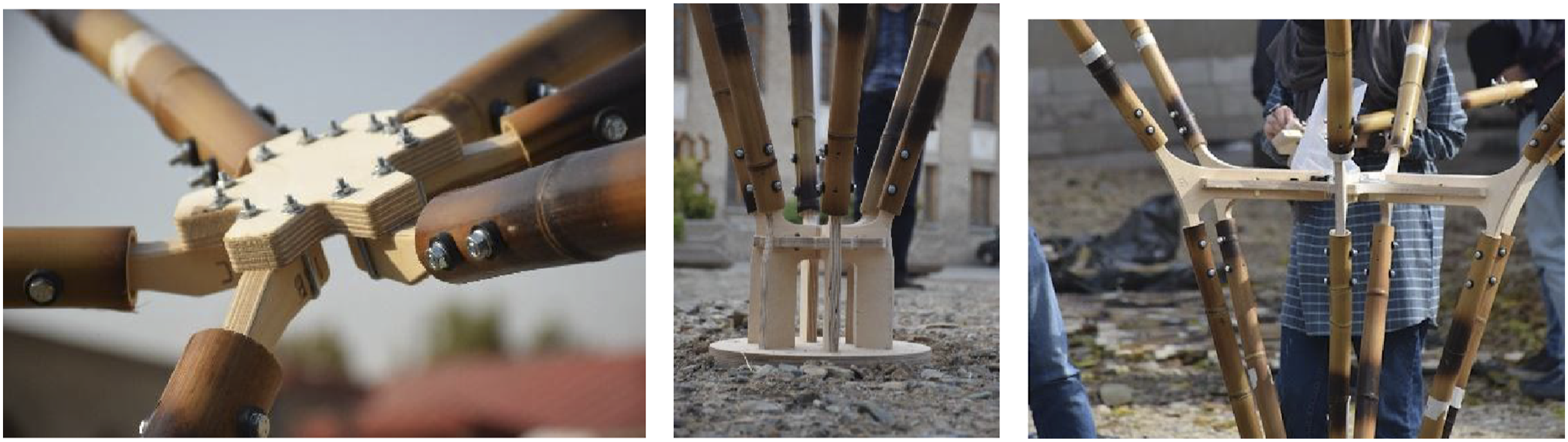
The construction stage involved three key steps: element production, pre-assembly, and final assembly. During production, nodes and handles were fabricated from plywood using shop drawings generated from the BIM process, while bamboo culms were cut to length and drilled using the customized CNC mechanism. Pre-assembly of handles and bamboo culms began immediately after production. Once labeled and sorted, the elements were ready to be transported to the construction site. The production and pre-assembly were completed in 5 days at the DCH fabrication laboratory. Due to pandemic restrictions, only a limited number of instructors and participants were allowed in the laboratory. at a time. In the final step, the pre-assembled elements were transported to the assembly site and arranged according to assembly order. The final structure was assembled collaboratively in about 7 hour by 20 students and six instructors at the University of Art’s main campus in Tehran. An assembly plan extracted from the BIM model was provided to guide participants through the process. Assembly began with the supports, gradually progressing toward the center and completing the peripheral cantilever sections. The ordered assembly, the lightweight elements, and the rigidity of the support connections to the ground enabled scaffold-free assembly. Participants temporarily held semi-assembled elements at critical points until additional elements were added. Once a rigid triangular configuration was formed, temporary support was no longer needed (Figure 21, Figure 22, Figure 23). Students and instructors assembling the structure. Final product installed at the University of Art campus. Connections final detail.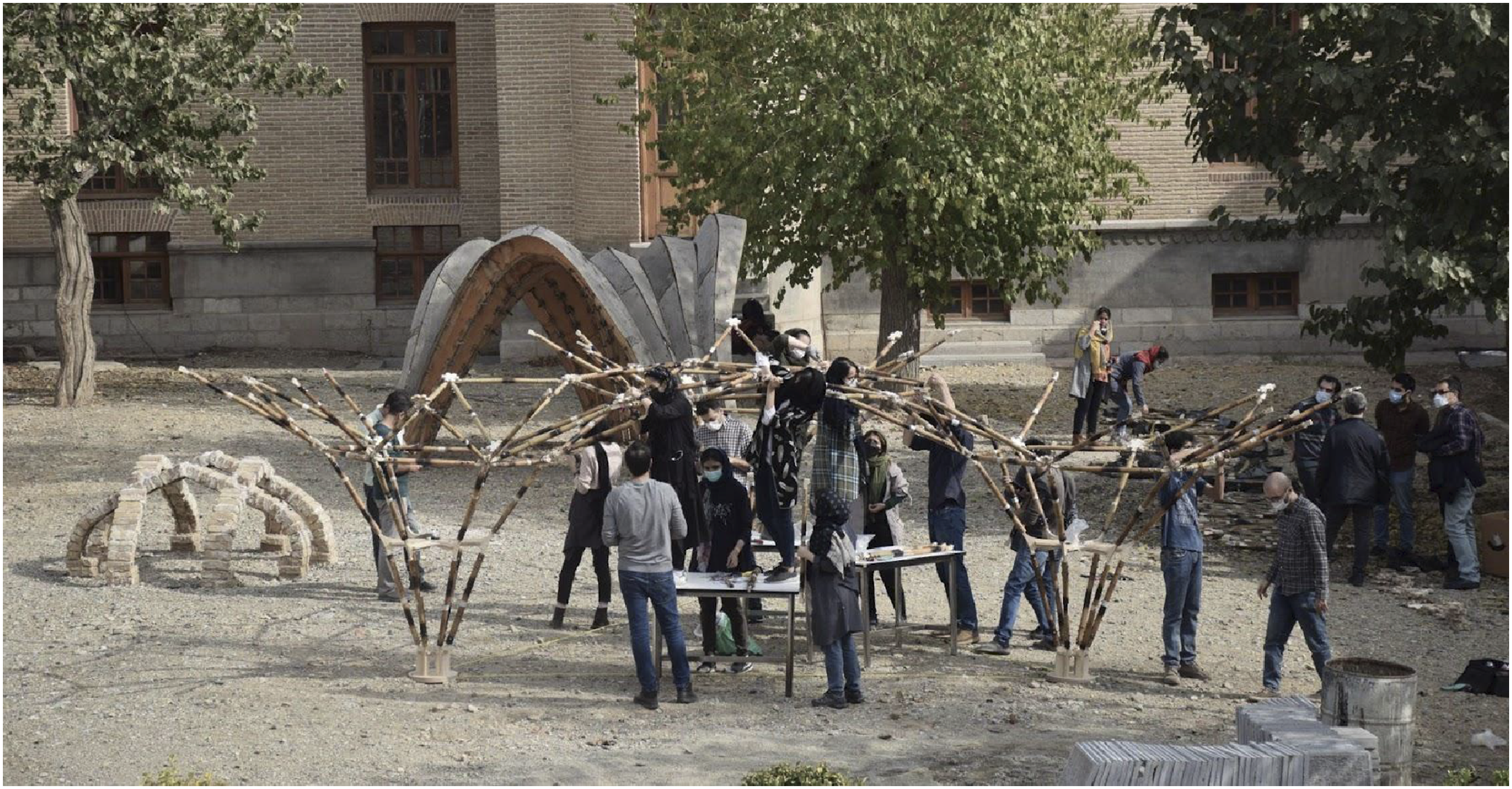
Discussion
The integration of computational design and digital fabrication into architectural studies offers new avenues for design exploration and addressing intricate design and fabrication tasks. The workshop presented in this paper aimed to devise an integrated design-to-fabrication workflow for bamboo spatial structures through a 12-week hybrid workshop. This case study included various stages: study, structural system design, fabrication preparation, and final fabrication phases. The major challenges in the workshop were finding the proper bamboo connection solution and developing custom software and hardware tools.
In the study phase, students reviewed preceding works that typically involved tying bamboo with fasteners or bands, reflecting on traditional methods, and utilizing active bending techniques. However, due to the limitations in bamboo length and the unavailability of fresh-cut green bamboo culms that can be easily bent, the focus shifted from active bending to node-based or nexorade structures, which required intermediary pieces.
Drilling was identified as the most suitable method, as it prevented fraying, maintained structural strength, and allowed for the attachment of intermediary pieces, thereby adapting the design to bamboo’s inherent properties. In examining examples of 3D-printed joints, it was observed that these designs may often rely on selecting straight and uniform bamboo pieces, making the effectiveness of the nodes highly dependent on the dimensions and geometry of the bamboo. Slight variations in size could compromise the nodes’ effectiveness.
To avoid material waste resulting from sorting and standardization, a joint detail was developed that could adapt to various bamboo diameters, with the primary requirement being that the joint fits within the bamboo. This way, bamboo culms can be of various pole radii and should only be larger than the handle’s diameter. However, a limitation of this design was the complexity of consistently ensuring the handle’s position remained centered on larger bamboo diameters. During fabrication, there were instances where students over-tightened the screws connecting the handles to the bamboo culms, causing the handles to shift off-center. To address this limitation, future research should explore adaptable joint designs that ensure joint remains centered on bamboo of varying diameters. Moreover, the use of bamboo as a suitable material for spatial structures warrants further research, particularly regarding its durability. The natural hollow structure of bamboo, which is susceptible to climatic conditions, raises concerns about long-term performance. Future studies should explore the application of appropriate adhesives and protective measures to enhance the material’s longevity and resilience over time.
The joinery design was implemented as a two-part system, a main node and secondary handles. Each handle was pre-assembled to bamboo culm from one side and then connected to the node from the other side and offered several advantages: • Reduced Geometric Complexity: The simplified geometry of the nodes allows the joint components to be manufactured from flat sheet materials using 3-axis CNC machines, which are among the most common and accessible fabrication tools globally. This approach increases the scalability and adaptability of the method, making it feasible for use in different regions, especially compared to nodes that require 3D printing, robotic processing, or more advanced equipment. • Simplified Bamboo-to-Node Connection: The intermediary handle between the bamboo culm and node takes on most of the joinery complexity on the bamboo side. Therefore, each bamboo piece required only four drill points, which helped preserve the bamboo’s natural shape and reduced the likelihood of damage during fabrication. Initial workshop research indicated that drilling caused the least harm to bamboo, making it a more suitable method for maintaining the integrity of the material while also addressing the challenge of non-standardized components. • Modular Design with Independent Components: Including an intermediary piece allows each bamboo to be independently detached for replacement or repair. Since the handle-node connection was fixed perpendicular to the bamboo axis, the element containing a bamboo culm and its tip handles could be easily detached from the structure without stress. Additionally, the triangular network of the structure, with its high degree of redundancy, permits the temporary removal of a few components for short periods without compromising the overall stability. • Reassembly and Sustainability: The connection details of the structure were designed for reassembly, allowing the structure to be easily dismantled and reassembled at a different location without damaging the components. This feature also supports the reuse of components, aligning with principles of sustainable and circular economy practices.
On the hardware side, the lack of commercially available CNC equipment to handle the irregular geometry and long length of bamboo posed a significant challenge. Connecting bamboo poles to joints with screw angles ranging from less than one degree to over 15 degrees further complicated the fabrication process. Standard CNC routers, limited to vertical drilling, were insufficient, prompting the development of a custom rotary CNC tool. This developed custom tool, with a plywood chassis, gripper, movable cone-shaped fixture for varying bamboo lengths, and precision rotation mechanism controlled by an Arduino Mega, highlighted the gap in available fabrication technologies for working with bamboo. Beyond its practical function, this custom solution served as an educational tool, giving workshop participants valuable experience in tool development.
While this setup effectively addressed the immediate fabrication challenges, it also raised questions about the scalability and generalizability of such bespoke solutions. Although successful in this context, the reliance on custom-built tools suggests a need for more adaptable, commercially available technology and workflow to accommodate sustainable construction materials’ unique demands. The bamboo drilling process, automated by integrating an Arduino program and CNC file based on BIM data, demonstrated high accuracy. However, the dependence on such tailored approaches may limit broader applications unless similar technologies become more widely accessible and integrated into mainstream fabrication processes.
The construction stage was planned so that a single person could assemble each element. Participants began assembling the structure simultaneously from three support points, with only three individuals actively assembling at any given time. Others assisted by handling secondary tasks such as providing nuts and screws, reviewing the assembly plan, preparing the next element, and stabilizing cantilevered components when needed. A team of four to six people is estimated to be able to complete the assembly within approximately 2 days. This process provided students with practical experience working with custom components and taught them the importance of assembly sequencing.
Conclusion
This workshop demonstrates the potential of computational tools and digital fabrication technologies in enabling precise, high-quality construction with biological materials like bamboo. By employing advanced computational design methods to address the inherent uncertainties of non-industrialized natural materials, the project explores innovative approaches to sustainable construction. Future research could explore alternative joinery techniques, such as enhanced fastening using advanced tools and integrating real-time feedback systems during fabrication to improve the precision and reliability of joint methods. Incorporating scanning technology to create a comprehensive inventory database will be essential, facilitating the accurate selection of the proper bamboo culm from the database. Additionally, incorporating an optimization step within the computational workflow can further refine the design and fabrication process, ensuring a more optimal integration of material and digital strategies. Through this work, we also engage with broader architectural entanglements, demonstrating how computational design and fabrication workflows can facilitate deeper architectural engagements with biological materials. By pushing the boundaries of how ecologically performative materials are utilized in construction, this research challenges traditional approaches and contributes to developing new and sustainable architectural solutions.
Footnotes
Acknowledgments
The authors would like to thank everyone who supported this research. Below is an alphabetical list of all students and instructors who participated in the workshop. Students: Aida Rafizadeh, Ali Khodabakhsh, Ali Nakhaei, Alireza Taghizadeh, Amin Ahadi, Amir Najimi, Amirmohammad Azizi, Arefe Payedar, Atoosa Sarrafi, Aysan Jafarzadeh, Donya Rahbari, Dorsa Seyedi, Elahe Tavakol, Elnaz GhareZiaeddin, Fateme Ebrahimi, Fateme Ghotbi, Gelareh Sanei, Hasan Fatemi, Hasti Jafarnejad, Hessan Shafagh, Kiana Saberian, Mahmoudreza Fenderski, Mahsa Matin, Mahya Akhavan, Marjan Khosravian, Maryam Shahrezaie, Masood Heidarpoor, Milad HasanAbadi, Mobina Babaei, Nahal Doosti, Neda Rafizadeh, Nima Azarang, Niusha Moghimi, Parnian Hasanpour, Raha Kamrava, Razieh Omid, Reza Taghavifard, Saman Keyhanian, Sana Rastegar, Sepehr Beyhaghi, Sepideh Sedghimehr, Soror Tarighi. Special thanks to Razieh Omid for her assistance in photography and project documentation. Instructors who are not co-authors of the paper: Dr Alireza Behnejad, Hanie Omid, Javad Allahgholi, and Seyed Ali Derazgisou. The authors would like to thank Dr Mohammadreza Matini and Dr Alireza Mostaghni for their support during the workshop and fabrication at the University of Art.
Declaration of conflicting interests
The author(s) declared no potential conflicts of interest with respect to the research, authorship, and/or publication of this article.
Funding
The author(s) received no financial support for the research, authorship, and/or publication of this article.