
Abstract
Spatial layout planning is a complex architectural problem involving numerous constraints and potential solutions. Conventional methods can be tedious and time-consuming, prompting recent research toward automated layout generation to create more design alternatives and ease the process. Presented here is a procedural model for spatial layout design, inspired by methods in game design and based on cellular automata. The model considers user inputs such as geometry, topology (direct and indirect adjacencies), and privacy requirements to automatically generate design options. The generated layouts satisfy input requirements and are generated deterministically through specification of seeds that have virtually no upper limit. The proposed method aims to support architects and designers in the layout planning process by combining algorithmic efficiency of cellular automata with a top-down approach to adhere to user-defined constraints. This method also has potential for integrating additional design objectives and user interaction in future developments.
Keywords
Introduction
Spatial layout planning is fundamental design task for architects to create layouts for functional spaces such as residential, commercial, and public buildings.1,2 It involves the careful allocation and organisation of space based on its users’ requirements of the number of rooms, size, and relationships between these rooms.2–6 Upon deciding the purpose and function of a space, designers specify geometrical and topological requirements to be satisfied 5 which can be expressed through visualisation tools like traditional bubble diagrams or adjacency matrices. However, the spatial layout planning process is iterative in nature, as designers and architects build upon and improve the design with each iteration. 7 Oftentimes, the resultant designs may also be inexhaustive of optimised solutions as designers may tend to rely on their own experience or intuition. As such, spatial layout planning can be a very tedious and time-consuming process.7,8 In view of these shortcomings, design approaches and methods have been proposed to tackle spatial layout planning with greater efficiency. By capitalising on advances in computation technology, the spatial layout planning process can be eased with the automated generation of design alternatives in a short amount of time.1,2,9 As a result, manual iterative work in the design process can be minimised alongside obtaining more diverse and optimised solutions.10–13
In recent years, different approaches have been proposed by researchers including the use of graphs, space allocation algorithms, evolutionary algorithms, and artificial intelligence to automate the process of layout planning.1,14 Wang et al. proposed a graph approach for generating floorplans given the input of room adjacency. 4 Using the input, dual graphs are constructed and modified into properly triangulated planar graphs through a set of transformation rules, and the generated plans offer designers with new design ideas and possible preliminary prototypes. Given an adjacency graph, Shekhawat et al. also demonstrated the generation of floorplans given a variety of input room shapes. 15 Apart from the use of graphs, evolutionary algorithms3,16 such as genetic algorithms are also proposed to solve the space allocation problem. Solutions derived through genetic algorithms have featured both single-floor and multi-floor, 3D spatial layouts optimised based on the specified size, geometry, placement and topological relationships.13,17–19 More recently, machine learning algorithms featuring deep neural networks such as generative adversarial networks (GANs) have risen to prominence.6,20–25 Models utilising GANs have been proposed by Nauata et al. 22 and Rahbar et al.6,23 to generate house and apartment layouts which are comparable to those that would be output by expert designers. GANs have also been shown by Chaillou 24 and Tanasra et al. 25 to automate the placement of furniture for a given layout. GANs are generally appropriate for generating layouts for predictable designs such as in residential spaces and workspaces but have not been widely applied to generate layouts for more complex, less predictable environments such as in public spaces.1,26
However, these emerging machine learning methodologies require large amounts of data for training models.27,28 Moreover, the quality of the training dataset is crucial in determining the quality of the solutions generated by machine learning-based methods.8,21 Large amount of quality data however is not yet readily available in the field of architecture, engineering and construction.1,21,24,27 Although there exists datasets such as RPLAN and LIFULL, 26 they come with limitations. For instance, the model which utilises a graph-constrained conditional GAN proposed by Aalaei et al. could not generate solutions for larger residential units with many rooms as the RPLAN dataset used to train the model did not include such kinds of plans. 8 In addition, the amount of data used to train machine learning models for floorplan generation has to be moderated; although large sets of data introduce diversity to the solutions, they are challenging to generalise. On the contrary, if the datasets are too small, they can be biased and under representative. In light of these limitations on the availability and usage of data for machine learning models, we look towards a method that capitalises on the data amplification capabilities of procedural modelling 29 which has seen wide implementation in the field of game design. 30 Through the use of a simple set of input parameters or generation rules, a large variety of virtual models of environments as seen in games with large open virtual worlds or dungeons can be automatically created.29,31,32 Such procedural modelling methods allow for faster times and lower costs for creating content with high levels of detail, 31 and players also stand to benefit from novelty and variety in their games. 30 The generation of these virtual worlds are automatic,31,33 and a complex model requires little data as it is represented by the specified set of rules which can be stored and shared in a compact form, generating the large actual model only when needed. 29 Also seen as a tool for game environment design, cellular automata (CA) is a concept first developed to represent self-replication in biological systems34,35 through exploring the use of mathematical properties of cellular structures and recursive growth processes. 36 The CA model is a dynamic system comprising of cells with a finite state set that changes at discrete time steps depending on the current state of itself and its neighbouring cells according to an update rule. Simple CA are capable of performing arbitrary computation tasks and generating highly complex arrangements, with well-known examples including Conway’s Game of Life 37 and elementary rule 110.38,39 Through the use of simple local rules, global complex behaviours and interesting geometric constructions arise, therefore CA is considered to be highly suitable for context-sensitive design exploration. 35 Hence, here we propose a procedural approach based on CA to automatically generate a variety of solutions that can fulfil the geometrical and topological objectives of spatial layout planning. Unlike conventional CA methods that are purely bottom-up, our approach targets architectural applications by incorporating top-down, global design constraints such as room area, adjacency, and boundary. Furthermore, the hybrid model has potential for future enhancements, including the incorporation of additional objectives of spatial layout planning and user interaction capabilities, which may further streamline the design process according to the design needs of architects and designers.
Layout generation procedure and CA algorithm
A comparison of properties between conventional CA and the proposed approach.

The program to generate the layouts is written and executed entirely in the 3D procedural software Houdini, (developed by SideFX). The program consists of built-in geometry nodes and custom geometry nodes whose function can be customised using VEX coding. A geometry node takes in an input which can be from another node or simply defined by the user, executes a geometry transformation function based on the VEX code, and outputs a result. The program is therefore created through connecting the geometry nodes with desired functions in succession of each other.
We use an example of a clinic to explain the working principles of the layout generation and CA algorithm. In the first geometry node of our program, the starting boundary within which the layout is to be fit into is drawn. It is then discretised into square cells (Figure 1(a)). The size of each discrete cell can be altered as desired by the user, however for illustration purposes we set the area of each cell as 1 m2. Design input for layout generation with a clinic as an example. (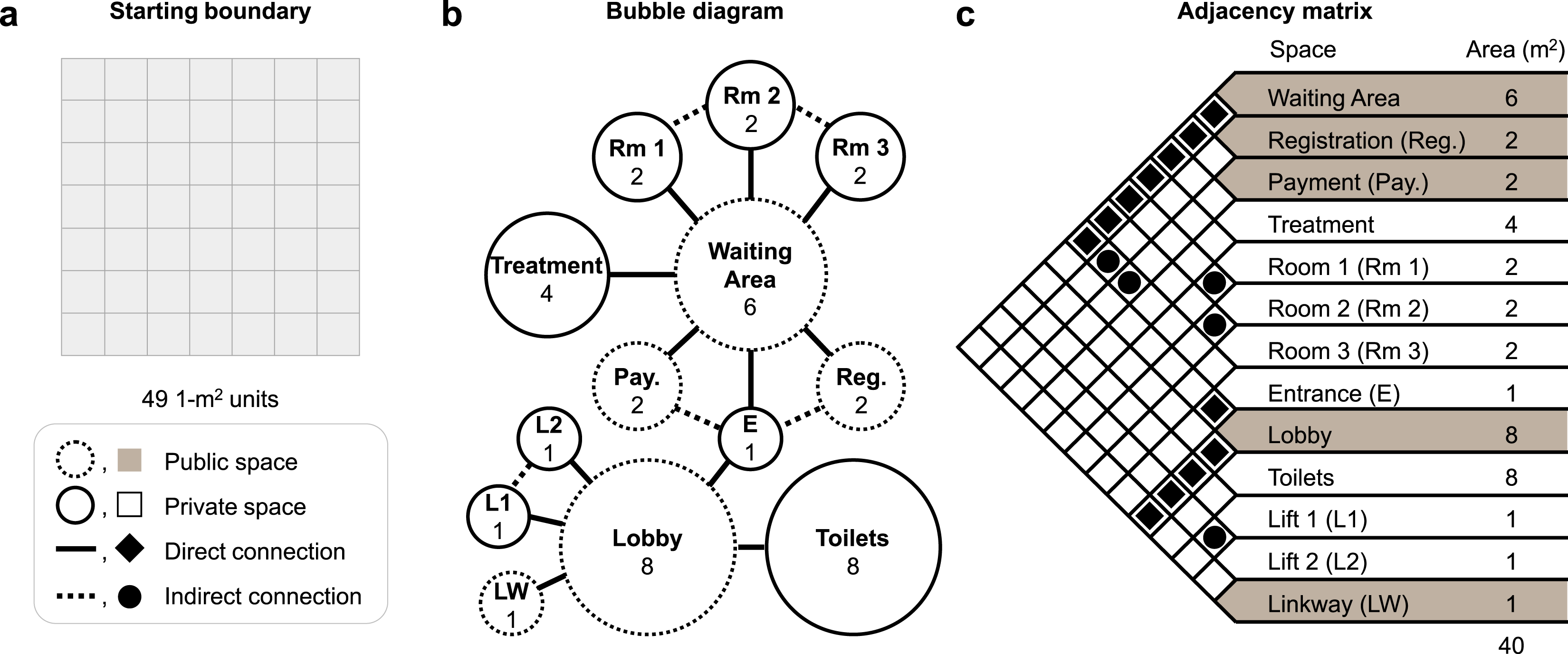
The geometrical and topological requirements shown in Figures 1(b) and 1(c) in the form of a bubble diagram and adjacency matrix are input into the program by the user through a custom geometry node with a custom user interface. In Figure 1(b), the straight solid lines and straight dotted lines linking bubbles represent direct and indirect connections between the spaces, respectively. The bubbles with solid and dotted borders indicate private and direct spaces, respectively. In Figure 1(c), the diamonds and circles mark direct and indirect connections between the listed spaces, respectively. The names of public spaces are shaded in the adjacency matrix. Within the custom geometry node, in addition to specifying the number of spaces, name of each space, and area of each space, the user can also make an indication if a particular space is a private or public space. Note that the area of each space directly corresponds to the number of cells that would be assigned to the space since the area of the cell is 1 m2 each. Thereafter, the user can specify the number of adjacencies, and for each adjacency select the two spaces (listed previously) and also indicate if it is a direct or indirect adjacency. Making the distinction between private and public spaces will not impact the layout of the spaces, but will later dictate the presence and size of doorways if the spaces in question have a direct adjacency. Spaces with indirect adjacency need only be next to each other without being connected by doorways.
Taking this information as input, we have another custom geometry node that classifies each space depending on the number and type of adjacency. The classification allows us to decide the order in which spaces are created based on their level of constraints. The first space to be created in the layout is the one that has the greatest number of adjacent spaces. In our example, this space is the Waiting Area. A Type I space is one that is connected to the first space or another already identified Type I space that has other adjacencies that are neither the first space nor other Type I spaces. For instance, the Entrance extends from the Waiting Area, and it is further connected to the Lobby which is not connected to the Waiting Area. We therefore classify the Entrance as a Type I space as well. Using this method of classification, the Lobby is also identified as a Type I space. The next set of spaces to be created in the layout are Type II spaces; these spaces are connected to more than one Type I space. In our example, the Payment and Registration are such spaces as they are planned to be adjacent to both the Waiting Area and Entrance. The last set of spaces are Type III spaces which are connected to only one Type I space. We also make a further distinction between the Type III spaces; for adjacent Type III spaces that share the same Type I connection, they are considered ‘linked’, whereas type III spaces that do not have any other adjacencies are considered ‘single’. Examples of linked Type III spaces include Room 1, 2 and 3, while the Treatment is a single Type III space. The classification of spaces for the clinic is shown in Figure 2(a). Classification of spaces and the CA-based algorithm for layout generation. (
The cell addition algorithm we propose is based on the CA concept where the next state of the cell is based on the current state of its neighbours.34,35 Our algorithm is iterative in nature, where in each iteration, a single cell is selected to be added to the existing space which can be just the starting cell or a cluster of cells representing the space. When selecting the next cell to add, only direct neighbours, otherwise known as the von Neumann neighbourhood, are considered as choices (corner cells, such as in the Moore neighbourhood, are excluded, Figure 2(b)). The choice cells are assigned a rank depending on the number of available cells in its von Neumann neighbourhood. For instance, if two out of three of the neighbouring cells do not belong to other spaces and are available, the cell is given a rank of 2 (Figure 2(b)). The ranking of the cell is a measure of its potential to expand the area of the space in later iterations. The cell that has the lowest rank is selected to be included into the space and if more than one cell shares the lowest rank, the cell to add is chosen (pseudo)randomly. The ranking of the cell also serves as an indication if a cell is closed off and isolated. Isolated cells are singular cells that are surrounded by other spaces or the border of the defined boundary for the layout. We aim to avoid isolated cells in the final layout as these will be voids which can be deemed as an inefficient use of space. At any iteration, the cell with the lowest ranking or potential to expand, which would be an isolated cell if it exists, is prioritised and added to the space being created. Doing so lowers the chance of such cells remaining available or unassigned in the final layout. The cell addition algorithm is executed with one cell being added to the space in each iteration until the number of cells added to the space is equal to its target area. Through the classification of spaces and the definition of the rules for cell addition, we can proceed with the layout generation.
From the discretised area, the cells are numbered pseudorandomly starting from ‘0’ (Figure 2(c)). The position of the cell numbered ‘0’ can be chosen by the user and it is automatically assigned as the starting cell for the first space. Specifying the original number of the cell in one of the geometry nodes, changes it to ‘0’, thus enabling the user to select the starting point for the first space. Figure 3(a) shows the reassignment of cell numbers based on the original numbering shown in Figure 2(c). The numbered cells form the basis on which the cell addition algorithm is performed using subsequent custom geometry nodes, according to the prior classification of spaces. Neighbouring cells are added one at a time to the starting cell using our cell addition algorithm until the total number of cells for that space is equal to its desired area. As cells are added to the space with the cell addition algorithm, they will be considered unavailable and are excluded from being added to other spaces. Selection of seeds in steps for each type of space to create layouts. (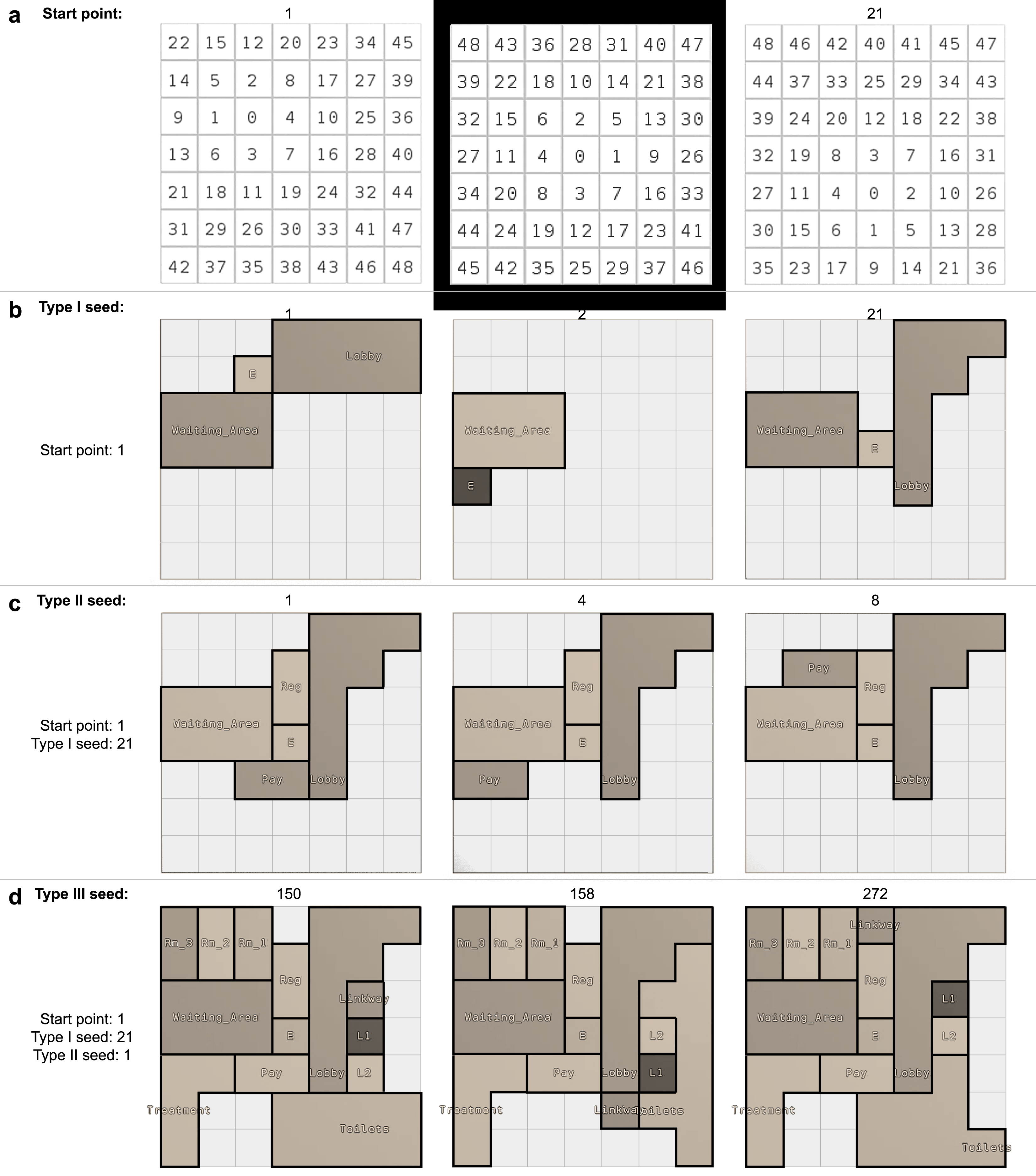
After the desired area has been achieved for the first space, the starting cell for next adjacent Type I space is selected amongst the available direct neighbouring cells of this first space. The selection of the starting cell positions for Type I spaces is pseudorandom and is based on a numerical seed that can be specified by the user; we hereby denote it as the Type I seed. After the starting cell is selected, neighbouring cells are added and rendered unavailable for other spaces based on the same aforementioned cell addition algorithm, until the total number of cells that constitute that space is equal to its desired area before moving on to create the next Type I space if any remain uncreated (Figure 3(b)). In Figure 3(b), note that for a given starting point (at cell numbered ‘1’), the location of the starting space, Waiting Area, remains the same.
When all Type I spaces have been created, that is, they all have their desired area, all remaining Type II and Type III spaces can be created by selecting the starting cells around the respective Type I spaces. We move on to create the Type II spaces. Since Type II spaces are to be adjacent to more than one Type I space, cells that are direct neighbours to the Type I spaces can be chosen. If no such cell exists, cells that are direct neighbours to one of the Type I spaces can be chosen. The starting cell is selected pseudorandomly out of the choices via a Type II seed. The Type II seed therefore controls the position of the Type II spaces in relation to the Type I spaces (Figure 3(c)). Unlike the creation of Type I spaces, the starting cells for all Type II spaces are selected concurrently and the cells to each Type II space is added in sequence based on the order of selecting their starting cells, allowing us to create the Type II spaces concurrently. For instance, in our clinic example, the starting cell for Payment is selected followed by the starting cell for Registration. Thereafter, in each iteration of the cell addition algorithm the next cells are chosen to be added to Payment first and then Registration, respectively. In this manner, the completion of one Type II space will not cordon off or hinder the creation of the other Type II spaces.
After creating all Type II spaces, we move on to create the Type III spaces. We first select a number of starting cells corresponding to the number of Type III spaces adjacent to the Type I spaces using a seed which we will term as the Type III seed. Going clockwise around the Type I space, the starting cells are assigned to both linked and single Type III spaces randomly using the Type III seed. However, when the starting space is assigned to a linked Type III space, the next starting cell will be assigned to the Type III space that shares a connection with it. This step increases the probability of linked Type III spaces being adjacent to one another when they are completed. Similar to the creation of Type II spaces, all Type III spaces are created concurrently after the selection of the starting cells. The layout generation is hence completed by choosing the starting point with a combination of the three seeds (Figure 3(d)).
Results and discussion
The proposed procedural model allows for the user to select the starting point and the respective seeds for building the different types of spaces at each juncture of the procedure. Figure 3(d) shows the final generated layouts for the same starting point, Type I and Type II seeds but different Type III seeds. Figure 4(a)–(c) shows three examples of different combinations of starting points and seeds that produce viable layouts. These six completed layouts all satisfy the geometrical and topological constraints that have been set and fit within the starting boundary as shown in Figure 1. It is important to note that at each stage, not all seeds will produce viable results (see Figure 3(b), where the Type I seed has a value of 2). Some seeds may fail to create the spaces or result in spaces that cannot reach their target area due to the selection and positioning of the starting cells. The selection of the starting cell for some spaces may fail as the existing space to stem from does not have sufficient neighbouring cells to accommodate all its required adjacencies. For instance, in Figure 3(b) where the Type I seed has a value of 2, the last Type I space to create (Lobby) must be adjacent to the Entrance. However, the Entrance only has two available neighbouring cells when on the contrary, it requires a total of three available neighbouring cells for the starting cells of its corresponding three adjacent spaces (Lobby, Payment, and Registration). As such, the Lobby is not created. In other cases, the growth of the space can also be constrained by the pre-defined starting envelope and as a result they are unable to expand and be built upon using the cell addition algorithm. For such scenarios, the program and user interface is designed in a way that the layout creation procedure will only be allowed to continue if the spaces created at that step possess the required area, else the user is prompted to select a new seed. This can be beneficial as it allows for user intervention and agency while creating the layouts. In this manner, the user controls the generation process by selecting the combination of starting point and seeds to create the final layouts that ultimately satisfy both the geometrical and topological requirements. In future, it will also be highly possible to have the option of a more automated approach by constraining the selection of seeds; the program could be tuned to include more checks and conditions such that it automatically searches for viable seeds only. Three examples of the final generated layouts based on input in Figure 1 (
In contrast to machine learning methods for generating layouts, large databases are not required in procedural generation. Rather, we see the data amplification ability of procedural generation as it creates a variety of design alternatives simply from the same set of inputs and rules. While we have observed that some seeds can produce the same result, there is virtually no upper limit to the seed number which may allow us to explore almost all possibilities of design variations. Our proposed method for layout generation is deterministic, that is, the same layout can be recreated as long as a user has the program file and the combination of starting point and seed numbers. In addition, the Houdini program file is ∼1 Mb in size, making it easily portable.
While the current procedural approach manages to generate layouts that can fulfil layout planning objectives of meeting the targeted geometrical and topological specifications, additional objectives and requirements of layout planning can potentially be further incorporated into the model. Owing to the procedural nature of the model, inclusions of such specifications can be applied to the overall generation procedure or reflected in the rules of the cell addition algorithm. To illustrate, by taking in additional input of whether the spaces are public or private, and if adjacencies are direct or indirect, we can add geometry nodes in the program to transform the generated layout into a three-dimensional model with walls. Thereafter, all walls between two directly adjacent public spaces are removed. On the other hand, a wall between two directly adjacent private spaces or between directly adjacent private and public spaces are removed and replaced with a doorway; the position of the wall removed can be random or user defined. Figure 4(d)–(f) shows a perspective view of the final generated layout with the walls and doorways created according to the new procedure. Therefore, the procedural approach has great potential to include other objectives of layout planning to create more functional spaces which can be explored in future. The ability to control parameters such as the number of corridors and also their configuration will be beneficial as they can enhance the spatial function and the depth of the space, improving wayfinding. 40 It will also be advantageous to be able to create spatial configurations that can potentially reduce step depth such as in an emergency department of a hospital. 21 Modifications can be made to the current CA-based algorithm to achieve the additional layout planning objectives such as good circulation and wayfinding within the layout. The procedural model may also benefit from further support by combining it with other methods like agent-based modelling and simulation.41–45 Some studies have also utilised CA to emulate characteristics such as crowd movement or pedestrian dynamics during evacuation,46–48 and such features have the potential to be accommodated in our cell addition algorithm to design spaces that facilitate better circulation in future. Furthermore, the current algorithm only adds one cell to one space at each iteration for simple implementation. However, a characteristic of CA is that local rules can be applied to all cells concurrently in a single iteration to result in a global effect.34,35 It will be beneficial to modify the rules of the current algorithm accordingly in order to reduce the likelihood of cordoning or hindering the creation of the different space types further (such as during the cell addition for our Type II and Type III spaces).
Our proposed approach is currently also limited in that the shape of the spaces are limited by the discretisation of the starting boundary into a grid of 1-m2 squares. As a result, the rooms in the layouts generated also take on angular and squarish forms. In reality however, some designers may possibly desire to generate rooms that take on more organic forms instead. This can be achieved by potentially reducing the area of each discretised unit and thereby increasing the resolution of the discretising grid in the proposed procedural model. In doing so, diagonal or curved walls can be better represented with the smaller grid units. Another possible avenue for exploration could be to use different methods of discretising the starting boundary, instead of using square shaped units, that can lead to the generation of more organic room shapes. In addition, while the example demonstrated is that of a relatively small clinic, in future we also hope to extend the application of this procedural model to larger, more complex, public spaces such as in airports, and museums, for instance.
At present, the program has neither been tested with professional designers nor does it include interactive features. A key future direction for this work involves the comprehensive evaluation and validation of the proposed method through a series of user studies, case studies, and comparative analyses. To ensure that the program meets the practical needs of designers, structured user studies with professional architects and design practitioners can be conducted. These studies will provide insights into the usability and overall effectiveness of the tool in various scenarios. Additionally, real-world case studies in architectural projects could be implemented to test the program’s performance under actual design conditions, where it can be evaluated against existing manual and automated design processes. Comparative analyses with current tools will also help benchmark the system’s capabilities, particularly in balancing automation with user control. Furthermore, the method’s adaptability to other design domains, such as urban planning or interior design, could be explored to extend its contributions beyond architectural layout generation. These validation efforts will provide critical feedback to refine the program, enhance the practical applicability of procedural generation for design automation.
In addition, while the current implementation fully automates the generation of spatial layouts, we also recognise the need for designer input, as complete automation may not always align with the creative processes inherent to design. In response, we plan to further develop our approach in future to incorporate user interaction. Specifically, the program can be adapted to provide an initial, fully automated layout suggestion, while users are allowed to manually modify the generated layout according to their preferences and requirements. The program can then also dynamically update the layout suggestion based on these user modifications, leveraging on the proposed method to ensure that the design continues to adhere to the specified geometrical and topological constraints. This human-in-the-loop approach thus strives to create a more collaborative design process that allows designers to retain meaningful influence over the final outcome by striking a balance between the efficiency and structure of automated layout generation and the creativity provided by designers.
Conclusion
Here, we have presented a procedural method with an algorithm based on cellular automata (CA) for layout generation with the intent of easing the tedious and time-consuming process of spatial layout planning by offering designers a variety of solutions given a set of geometrical and topological constraints. Our hybrid approach combines the bottom-up method of CA with a top-down design approach; unlike conventional CA models, which operate solely on local cell rules, our method considers user-defined requirements as global constraints as it automatically generates spatial layouts. These constraints are area, adjacency, and design boundary. The integration of user-defined constraints into CA expands the utility of procedural generation by procedurally generating layouts that are tailored to meet real-world design needs. The resultant different layouts were generated deterministically through the specification of seeds, where the seeds have virtually no upper limit. We believe that our work bridges a key gap in existing research by utilising the data amplification property of procedural modelling, which allows for a wide variety of layout configurations from minimal input—something that traditional machine learning approaches often struggle to achieve without large datasets. Our work not only advances procedural generation techniques for spatial layouts but also sets the stage for future research in hybrid systems that combine local and global control mechanisms. While the current method only satisfies the layout planning objectives of area and adjacency, its procedural nature potentially allows for the inclusion of more objectives of spatial layout planning such as room shape, 15 orientation, 49 shortest paths, 21 and even optimised energy performance.11,50 The approach also has the potential to be further adapted to other domains requiring flexible yet controlled generative design, in areas such as urban planning or even game level generation. To ensure its applicability in professional contexts, the model can be evaluated through usability testing with designers, allowing for feedback that will guide future refinement. Additionally, further developments can potentially introduce opportunities for user interaction and control over the generated layouts, enhancing integration of automation with designer- driven modifications. We believe that this work represents a step towards enhancing the architectural design process by incorporating more complex objectives and interactive capabilities that can better support designers in creating improved spatial layouts.
Footnotes
Declaration of conflicting interests
The author(s) declared no potential conflicts of interest with respect to the research, authorship, and/or publication of this article.
Funding
The author(s) received no financial support for the research, authorship, and/or publication of this article.