
Abstract
The physical mechanisms operating during the penetration and perforation of metallic and concrete targets by rigid projectiles are reviewed in this paper. The review covers our approach to these phenomena, as detailed in several papers that were published during the last decade. This approach is based on experimental data and their numerical simulations, through which we constructed analytical expressions for the penetration depths and the ballistic limit velocities of the corresponding projectile/target pairs. This review article will benefit researchers in the terminal ballistics community because it presents a full picture of our approach to the subject, and it also outlines the development in our thinking over the years.
Keywords
Introduction
This article reviews our work on the penetration and perforation processes of rigid projectiles impacting metallic and concrete targets, which was published in several articles during the last decade. The main issue in these processes concerns the resisting stresses exerted by these targets on the rigid projectile during its penetration or perforation. These stresses are directly related to the decelerations of the rigid projectile, which can be determined by one (or more) of the following ways: (1) direct measurement of the deceleration with a gauge embedded in the projectile, (2) inferring the deceleration directly from experimental data, and (3) using numerical simulations with properly calibrated material properties, to follow the whole penetration process. We employed the last two procedures throughout our work, as will be demonstrated in this review. Thus, the projectile’s deceleration in a semi-infinite target is derived from the published data for the penetration depth as a function of its impact velocity. We then use numerical simulations to quantify these decelerations (resisting forces) for different targets and for various projectile geometries. We should note that our approach to numerical simulations is unique in the sense that we use them to derive analytical models for various projectile/target interactions. We should also note that one can find different models to account for these interactions, as detailed in the review articles of Anderson (2017) for metallic targets, and in Liu et al. (2022) for concretes. We do not wish to confront our models with other approaches and, instead, we briefly mention such controversies in several instances throughout this summary.
Metallic targets
This section reviews our work on the penetration and perforation of metallic targets by rigid projectiles at normal and inclined impacts. The most important material property in these interactions is the resisting stress (Rt) which the target exerts on the projectile. The resisting stress is closely related to the dynamic compressive strength of the target material (Y). To simplify the analyses, we often use a von-Mises dynamic stress for the constitutive relation of the target material. This choice was justified by Rosenberg et al. (2018a) who showed that the average strain and strain rate in a penetrated metallic target are 0.27 and 104 s−1, respectively. Thus, the dynamic compressive strength (Y) for a given target, in numerical simulations, should be determined by a high-rate Kolsky-bar test at a strain of 0.27, with specimens taken from the target. For example, Rosenberg et al. (2018a) showed that for the 6061-T6 aluminum alloy the effective dynamic strength is Y = 0.43 GPa. Another conclusion regarding numerical simulations, from Rosenberg and Dekel (2009a), is that to achieve their convergence one must use a mesh size of at least 11 cells on the projectile’s radius at the central region of the target around the impact point.
Deep penetrations
Rosenberg and Dekel (2009a) chose the excellent set of data from Piekutowski et al. (1999), in order to determine the behavior of rigid projectile during a deep penetration process. We should note that the analytical model presented in Piekutowski et al. (1999) is based on the dynamic cavity expansion analysis. This model is very different from our model in Rosenberg and Dekel (2009a), where the target’s resistance was derived directly from the data of Piekutowski et al. (1999). This approach was applied to other projectile/target interactions as reviewed here. Namely, we use experimental data to derive the nature of the resisting stresses (constant or velocity-dependent) and quantify them by using numerical simulations.

Test results from Piekutowski et al. (1999) and the corresponding average decelerations.
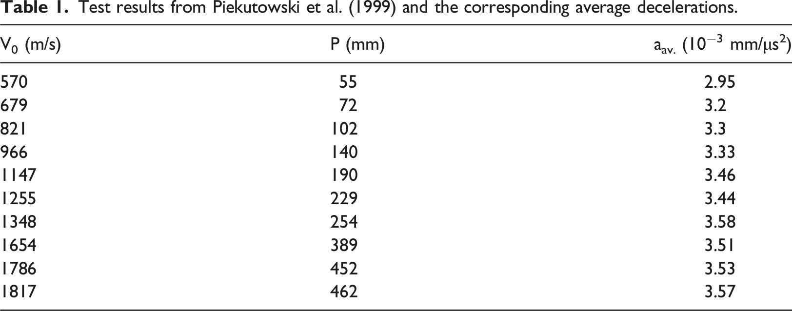
The fact that the average decelerations are independent of the impact velocity means that the resisting stress exerted by the target on the projectile is independent of its instantaneous velocity. Thus, the constant deceleration model accounts for the data in Piekutowski et al. (1999) as shown in Figure 1, which includes their data for two types of ogive-nosed steel rods. Rosenberg and Dekel (2009a) showed that other sets of data, for conical and spherical nosed rods impacting similar aluminum targets, follow the same features. Thus, all these rigid rods experienced a constant deceleration during their deep penetration, which was shown to depend on the nose shape of the rod. The agreement between equation (1) and the test results of Piekutowski et al. (1999).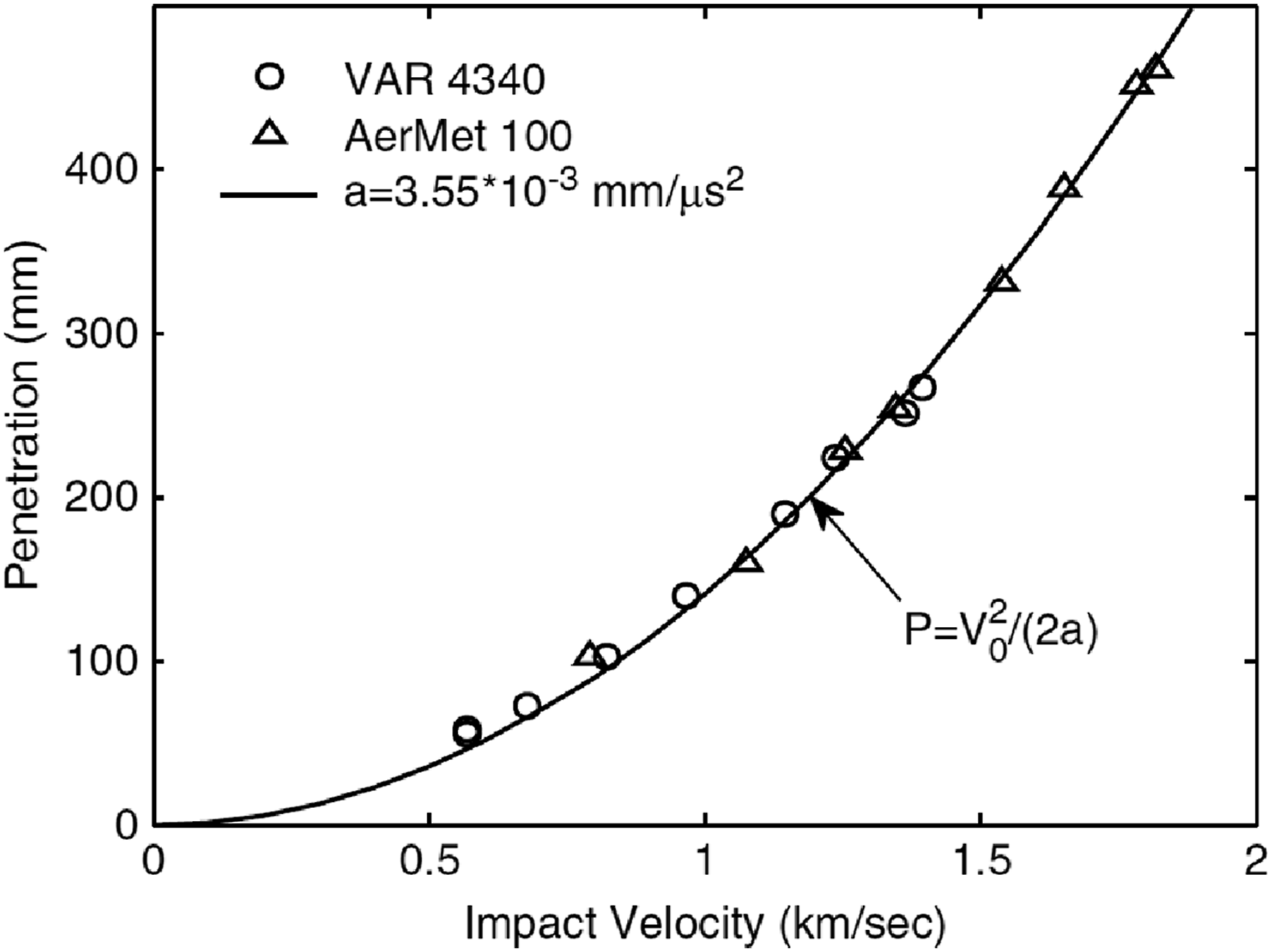
The second route to explore the issue of projectile deceleration is through numerical simulations, as was demonstrated by Rosenberg and Dekel (2009a). They used the 2D version of the AUTODYN hydrocode with a simple elastic-plastic von-Mises criterion for the dynamic strength of various aluminum and steel targets. The long steel rods were given a very high strength (50 GPa) to avoid their yielding or failure during penetration. Figure 2 shows the deceleration-time history of an ogive-nosed long steel rod impacting an aluminum target, with strength Y = 0.4 GPa, at an impact velocity of 1.0 km/s. One can clearly see that after a relatively short entrance phase (the shaded area in the figure), the deceleration of the rod is, indeed, constant throughout the rest of the process. Similar deceleration histories were obtained for other impact velocities, resulting in the same values for the constant deceleration after an initial entrance phase. These results strongly enhance the main conclusion for the constant deceleration conjecture, as derived above by analyzing the test data of Piekutowski et al. (1999). Deceleration history of an ogive-nosed steel rod impacting an aluminum target at 1.0 km/s.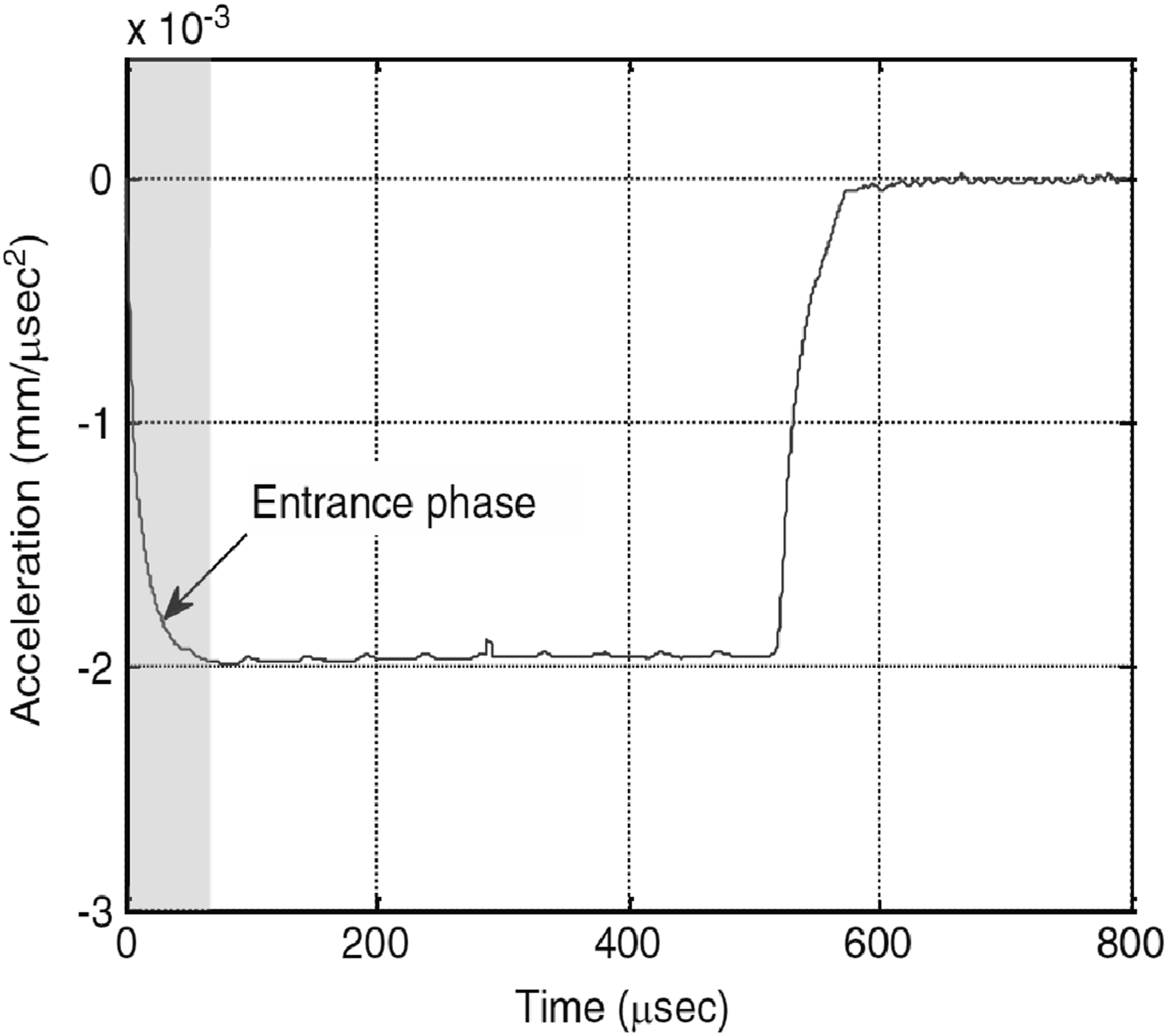
Similar results were obtained by Rosenberg and Dekel (2012) for rods with other nose shapes: spherical, conical, and flat. Obviously, the constant deceleration of these rods depends on their nose shapes, as well as on the strength of the target material. Once the constant deceleration of rigid projectiles is established, one can write their equation of motion (Newton), F = Ma = RtπD2/4 = const. Here, Rt is the constant resisting stress on the projectile, M and D are the projectile’s mass and diameter, respectively. Integrating this equation (twice) leads to the following penetration equation:

According to this relation, a short projectile will experience a higher deceleration than a longer one, while penetrating the same target. This is clearly seen in Figure 3, from Rosenberg and Dekel (2009a), which shows the deceleration histories of two ogive-nosed steel rods of different lengths, impacting an aluminum target (Y = 0.4 GPa), at V0 = 1.0 km/s. Deceleration histories of rigid rods with different lengths.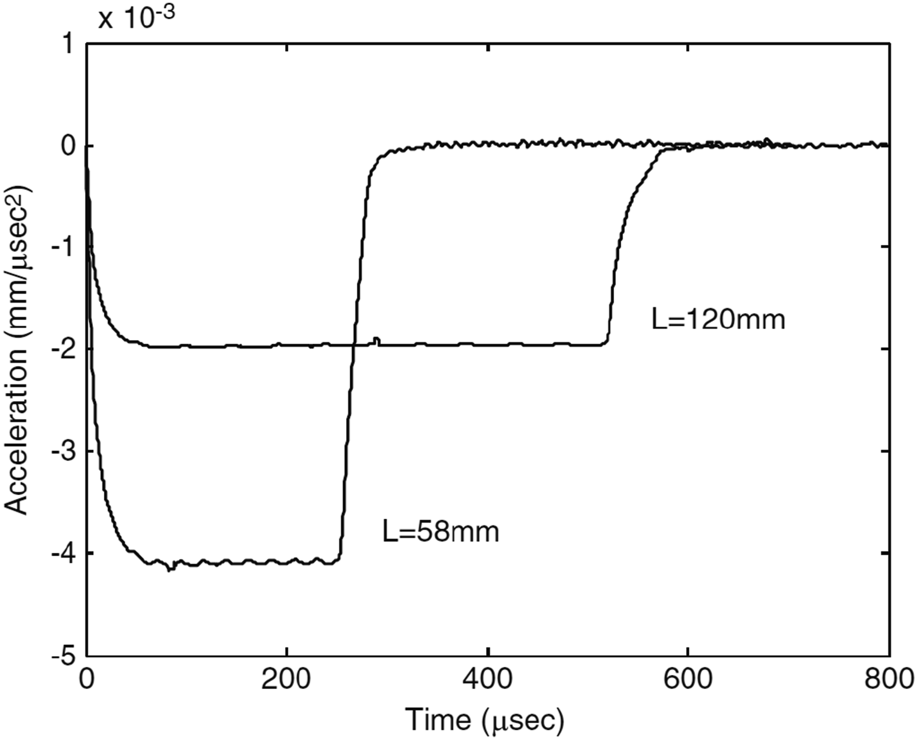
As was shown by Rosenberg and Dekel (2012), the constant resisting stress (Rt) which the target exerts on the rigid projectile, depends on the target’s strength and on the projectile’s nose shape. They performed a large series of numerical simulations for long rods with various nose shapes, impacting aluminum and steel targets of different strengths. These simulations resulted in values for the constant decelerations, which were inserted in equation (3) to derive the corresponding values for Rt in each case. The resulting Rt values were presented in a normalized way for Rt/Y as a function of ln (E/Y), where E is the Young’s modulus of the target material. The results were found to follow straight lines according to:

Rosenberg et al. (2020a) and Rosenberg and Vayig (2023) also dealt with the contribution of the entrance phase to the total penetration depth of rigid projectiles with different nose shapes. Using 2D numerical simulations they followed the deceleration-time histories of long rods having spherical nose shapes (CRH0.5) and ogive-nosed rods with CRH2, CRH3, CRH5, and CRH8. From the constant decelerations (a), they derived the corresponding values of Rt for these rods, through equation (3). These Rt values determine the penetration depths during the constant deceleration phase in each case, through equation (2). Their next step was to use the simulation results for the total penetrations (Ptot) to determine the contribution of the entrance phase (Pent) through the relation:
from which they determined the values of Pent for each rod in these simulations. The results showed that the contribution of the entrance phase is linearly related to the diameter of the rod: Pent = kD. The values of k were found to be slightly dependent on the impact velocity and on the target’s strength, but their average values could be expressed by:
Comparing our predictions with the test results of Piekutowski et al. (1999).
So far, the analysis focused on the low and medium range of impact velocities. Once these velocities are raised beyond a certain threshold value, the picture changes. The first evidence for this change is the appearance of penetration channels with diameters larger than those of the projectiles’ diameters. This phenomenon was termed “cavitation” by Hill (1980), and it is shown schematically in Figure 4. The cavitation phenomenon according to Hill (1980).
Hill (1980) assumed that this cavitation phenomenon for ogive-nosed projectiles occurs at impact velocities beyond a certain threshold velocity (Vcav). For spherical and conical-nosed projectiles his model resulted in cavitations at all impact velocities. However, the penetration channels in the tests of Forrestal et al. (1988) showed no cavitation for such projectiles, even at high impact velocities as seen in Figure 5. Penetration channels of rods with conical and spherical nose shapes.
The cavitation issue was dealt with in Rosenberg and Dekel (2012) and in Rosenberg et al. (2020a), using numerical simulations for rigid rods with different nose shapes, impacting various targets at high velocities. These simulations showed that cavitation phenomena take place for all nose shapes, at impact velocities above the corresponding threshold velocities (Vcav), that depend on the nose shape of the projectile. The cavitation phenomenon is manifested by a non-constant deceleration of the projectile as demonstrated in Figure 6, which follows the deceleration of a spherical nosed rod impacting an aluminum target at 2.5 km/s, from Rosenberg and Dekel (2012). The high deceleration of the projectile at the early stages of penetration, is the result of the extra energy which the projectile has to invest in the target by enlarging the penetration channel’s diameter (cavitation). Deceleration history of a spherical-nosed steel rod impacting an aluminum target at 2.5 km/s.
The numerical study of Rosenberg and Dekel (2012) showed that for each nose shape there is a specific threshold velocity (Vcav) above which the deceleration of the projectile is not constant. They derived a simple relation for Vcav in terms of the target’s resisting stress (Rt), its density (ρt), and the nose shape of the projectile (b):
Inserting equation (9) in equation (2) results in a simple relation for the normalized penetration depth at V0 = Vcav:

The extra energy which the projectile “invests” in expanding the channel’s diameter, when V>Vcav, is manifested by an inertial term (ρtV2) which has to be added to the constant resisting stress (Rt) of the target. Rosenberg and Dekel (2012) assumed that for velocities above Vcav, the target’s resisting stress (Σt) is given by:

Inserting this expression in the equation of motion (Newton) results in, after integration, the following relation for the penetration depth at high impact velocities (V0>Vcav):
Since the values of Vcav for actual targets are relatively high, it is difficult to find experimental results for deep penetrations of rigid projectiles at V0>Vcav. Instead, the analytical relation in equation (13) was compared by Rosenberg and Dekel (2012) with their simulation results for high velocity rigid rods with different nose shapes, impacting various aluminum and steel targets. This comparison is shown in Figure 7 and the excellent agreement between model predictions and simulation results enhances the validity of this approach. Note that in order to simplify the notations, Rosenberg and Dekel (2012) defined the entity x=(V0/Vcav)2. We should also note that the cavitation phenomenon was dealt with, analytically, by Rubin (2012) and by Rong and Li (2019), and their findings are in agreement with the simulation results of Rosenberg and Dekel (2012). Comparing model predictions and simulation results for high velocity rods of different nose shapes impacting various aluminum and steel targets.
Plate perforation
The perforation process of metallic plates is affected by their back surface which complicates the analytical modeling of these interactions. Moreover, the back surface has different effects on the penetration process of sharp-nosed and blunt-nosed projectiles. The perforation process of a ductile metallic plate by a sharp nosed projectile was analyzed by Rosenberg and Dekel (2009b) and by Rosenberg and Dekel (2012), through 2D numerical simulations. They introduced the concept of an average resisting stress (σr), which the plate exerts on the projectile during perforation. This effective resisting stress takes into account the effects of the entrance phase due to the impact face, and that of the exit phase due to the back face of the plate. Using energy conservation considerations, they showed that the ballistic limit velocity of a given projectile/plate pair, is given by:


The ballistic limit velocity of a given projectile/plate pair can be determined by experiments as the average between the highest impact velocity which does not result in plate perforation, and the lowest impact velocity which results in a complete perforation. Another way to infer the value of Vbl, for a sharp-nosed projectile perforating a metallic plate, is to use the well-known relation of Rechet and Ipson (1963) which is based on energy conservation considerations:

The ballistics tests of Rosenberg et al. (2018a) included plates of 6061-T6 aluminum and C-101 copper of similar thickness. The Kolsky-bar tests on specimens taken from these plates showed that these metals have very similar stress–strain curves at high strain rates. In particular, the dynamic flow stress, at a rate of 5 × 10³ s−1 and at a strain of εp = .27, was found to be Y = 0.43 GPa for both materials. According to the relations above, the two plates should have the same Vr (V0) data and the same values for their Vbl, when perforated by a given projectile. To check this prediction, Rosenberg et al. (2018a) used the hard steel core of the AP 7.62 mm projectile. Their test results could be represented by the same curve of Vr (V0), with the same value for Vbl, as shown in Figure 8. We should note that the model (dashed curve in Figure 8) refers to equation (15c), since the aluminum and copper plates in these tests had thicknesses of about 8 mm (H>D). The model (dashed curve) compared with results for the copper and aluminum plates (symbols).
The numerical simulations of Rosenberg and Dekel (2012) for thick plates (H>D), that led to the relation in equation (15c), were revised by Rosenberg and Vayig (2023). They performed numerical simulations for various plate materials having higher thicknesses, with the realization that the values of σr should asymptotically approach the corresponding values of Rt. The simulations confirmed this conjecture, as can be seen in Figure 9, and the following relation for σr/Y was found to fit their simulation results: Simulation results for two targets showing the asymptotic approach of σr to Rt.

The contribution of friction on the shanks of rigid projectiles to the target’s resisting stress is a long standing problem, since very few data have been published on the sliding friction of metals at high velocities. Thus, one can find different friction coefficients in various penetration models that were published over the years. Our approach to this issue is, again, based on analyzing experimental data, rather than using a-priory assumptions. Rosenberg and Vayig (2021a) analyzed the data of Rosenberg and Forrestal (1988) for two types of long steel rods perforating 6061-T651 aluminum plates with a thickness of 25.4 mm. These conical-nosed rods had the same weight, and they are shown in Figure 10 as the regular rod and the rod with the cut-back shank to eliminate the friction on its shank. The two types of steel rods used by Rosenberg and Forrestal (1988).
The experimental results of Rosenberg and Forrestal (1988) showed that for impact velocities in the range of 300–400 m/s, the residual velocities of the rod with the cut-back shank were higher than those of the regular rod, resulting in a lower ballistic limit velocity for the cut-back rod. The difference between the residual velocities of the two rods was attributed to the friction’s effect, which was found to diminish at higher impact velocities, indicating that the friction is practically insignificant at sliding velocities above 400 m/s. Rosenberg and Vayig (2021a) used the following relation for the dynamic coefficient of friction (μd) in their numerical simulations of these experiments:
Rosenberg et al. (2021) used 2D numerical simulations to explore the possible occurrence of cavitation phenomena in metallic plates perforated by sharp-nosed rigid projectiles. They followed the diameters of the perforation holes (Dh) in plates of different materials and found cavitation to occur at impact velocities above certain thresholds velocities (Vcav). At velocities higher than Vcav, the simulations resulted in values of Dh larger than the projectile’s diameter (D). The values of Vcav followed a relation like that given in equation (9) for semi-infinite targets, with Rt replaced by the effective resisting stress of the plate (σr), namely Vcav=(σr/2bρt)0.5. The simulations were performed for aluminum, steel, and tungsten plates with a dynamic strength of Y = 0.5 GPs. The plates had the same thickness as the projectiles’ diameter (H = D), and the rigid steel projectiles had either ogive or conical nose shapes. Figure 11 shows the simulation results of conical-nosed projectiles, for the normalized hole diameter (Dh/D) as a function V0/Vcav. Cavitation is clearly demonstrated for V0>Vcav in each set of simulations. Simulation results for the normalized hole diameters in plates of different densities.
Inclined impacts
The penetration process of rigid projectiles impacting metallic targets at various inclination angles was explored in several publications, as detailed here. The 3D numerical simulations of Vayig and Rosenberg (2021a) explored the effect of yaw on the deep penetration of various rods into different targets, for yaw angles up to θ = 20°. The simulation results were presented in terms of the normalized penetration depths (P/P0) as a function of θ, where P0 is the depth of penetration at normal impact. Figure 12 shows the simulation results for steel rods with different aspect ratios, impacting an aluminum target at a velocity of 1.0 km/s. Clearly, the normalized penetrations are insensitive to the projectile’s aspect ratio. Normalized penetrations vs. yaw angle for rigid projectiles with different aspect ratios.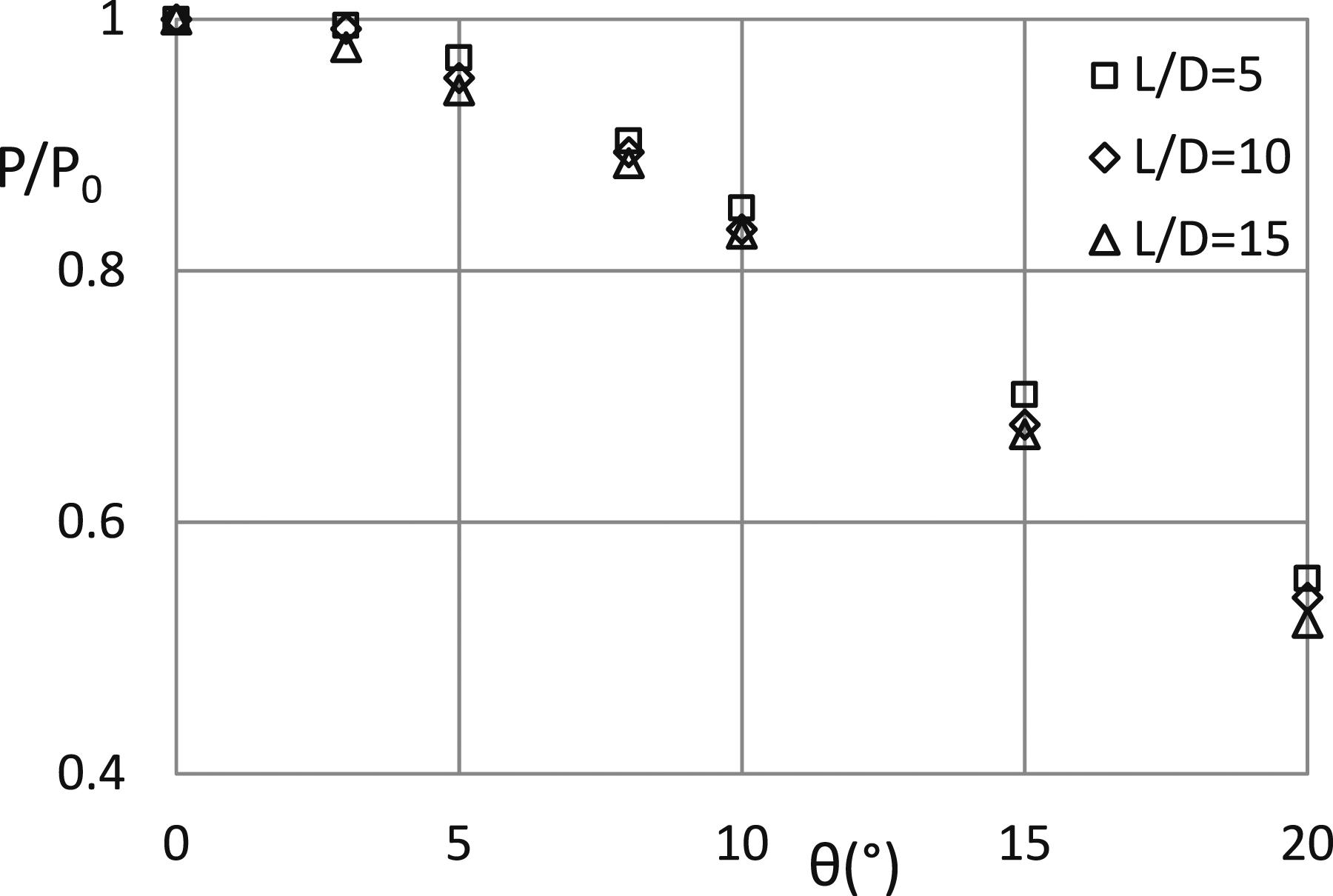
Vayig and Rosenberg (2021a) explored the role of the relevant material properties on the penetration depths of yawed projectiles, such as their impact velocity and their density, as well as the target’s strength and density. They defined a critical yaw angle (θc) for each projectile/target pair with which one can obtain a single curve for different impact velocities. One can interpret these critical angles as the maximal yaw angles which will have practically no influence on the penetration depth. The simulation results were found to be normalized through the following relation: Simulation results and model predictions for different impact velocities.

The corresponding values of θc were found to depend on the ratio A = Rt/ρpV02 between the target’s resistance to penetration and the impact pressure of the projectile, through:
The numerical study for penetration process of rigid projectiles obliquely impacting semi-infinite metallic targets, was investigated In two recent publications. Vayig and Rosenberg (2021b) explored these features for ogive-nosed rods, and Vayig et al. (2023) studied these impacts for spherical nosed rigid projectiles. The two studies reached similar conclusions regarding the trajectory changes of these projectiles during penetration, as well as their final penetration depths. The projectile’s obliquity (α0) in these works was defined as the angle between its axis and the target’ face.
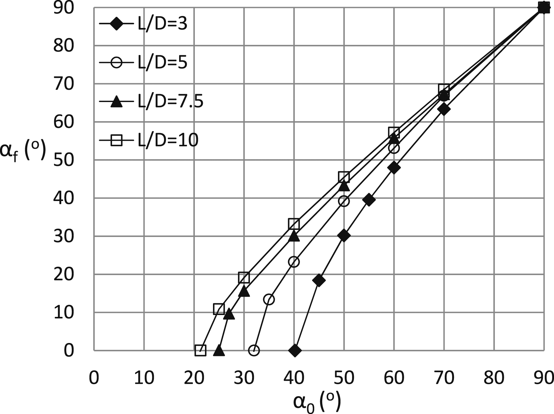
A rigid projectile impacting a thick target at an initial obliquely (α0) will experience an asymmetric force at the early stages of penetration, which will affect its trajectory in the target. The final angle between the projectile’s axis and the target’s face (αf) was found to follow the relation: Simulation results (symbols) and the curves drawn through equation (21).
The values of αric were found in Vayig and Rosenberg (2021b) and in Vayig et al. (2023) to be related to the non-dimensional entity A = Rt/ρpV02, which was found to play an important role in the penetrations of yawed projectiles. For L/D = 5 projectiles they found that:


The normalized penetrations (P/P0) of rigid projectiles obliquely impacting metallic targets, were found to be related to the threshold ricochet angles (αric). The obliquity (β0) was redefined as the angle between the projectile’s axis and the normal to the plate’s face, namely, β0 = 90o- α0. The simulation results of Vayig and Rosenberg (2021b), for ogive-nosed projectile, followed the relation:


Figure 15 demonstrates the validity of these relations for L/D = 5 ogive-nosed projectiles, by comparing their predictions with the numerical results. Similar agreements were shown in Vayig et al. (2023) for spherical nosed projectiles. Simulation results (symbols) and model predictions (dashed curves) for the normalized penetrations as a function of obliquity.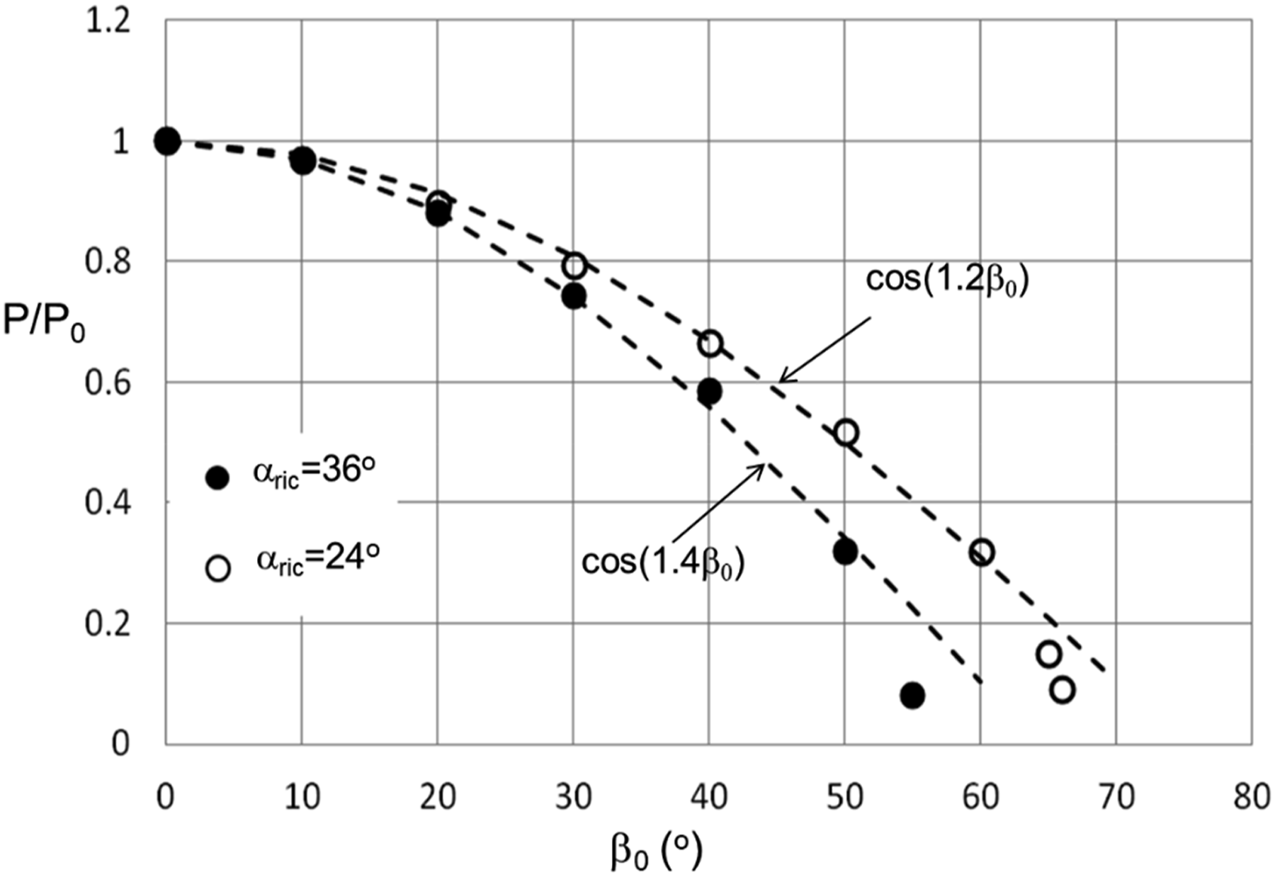
The ricochet process of rigid projectiles obliquely impacting metallic plates was studied by Vayig and Rosenberg (2023) with 3D numerical simulations. Figure 16 shows three possible outcomes from oblique impacts of L/D = 5 rigid steel projectiles on an aluminum plate 30 mm thick. Through such simulations we were able to determine the values of threshold ricochet angles (αric) to within The three possible modes of interaction between a rigid projectile and a metallic plate.
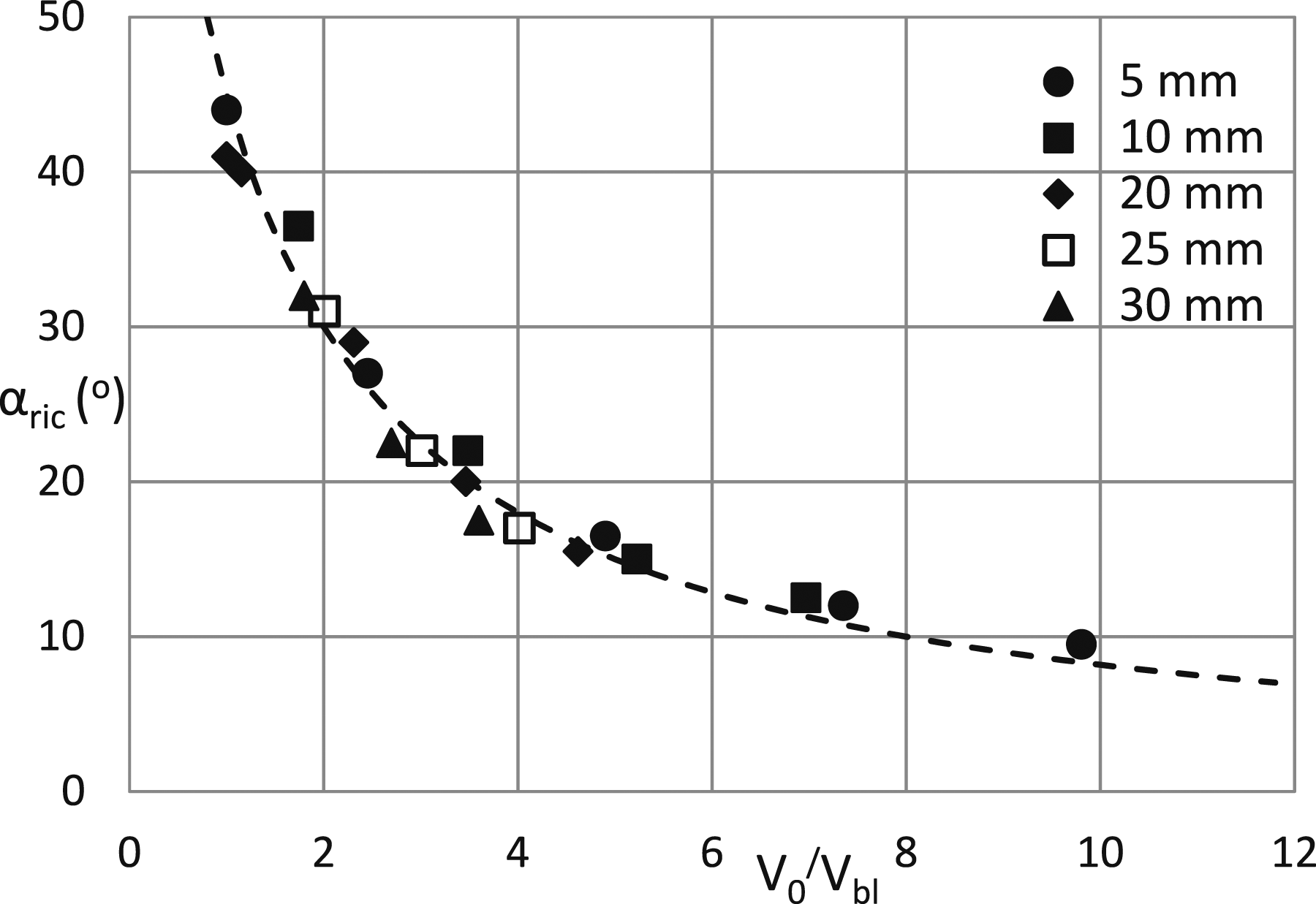
The threshold ricochet angles were found to be related to the normalized impact velocity (V0/Vbl) of the given projectile/plate pair, through the relation: Simulation results (symbols) and model prediction (dashed curve) for L/D = 5, CRH3 projectiles impacting aluminum plates (Y = 0.43 GPa) having different thicknesses.
Concrete targets
Deep penetration
The data from Frew et al. (1998) and the inferred average decelerations.
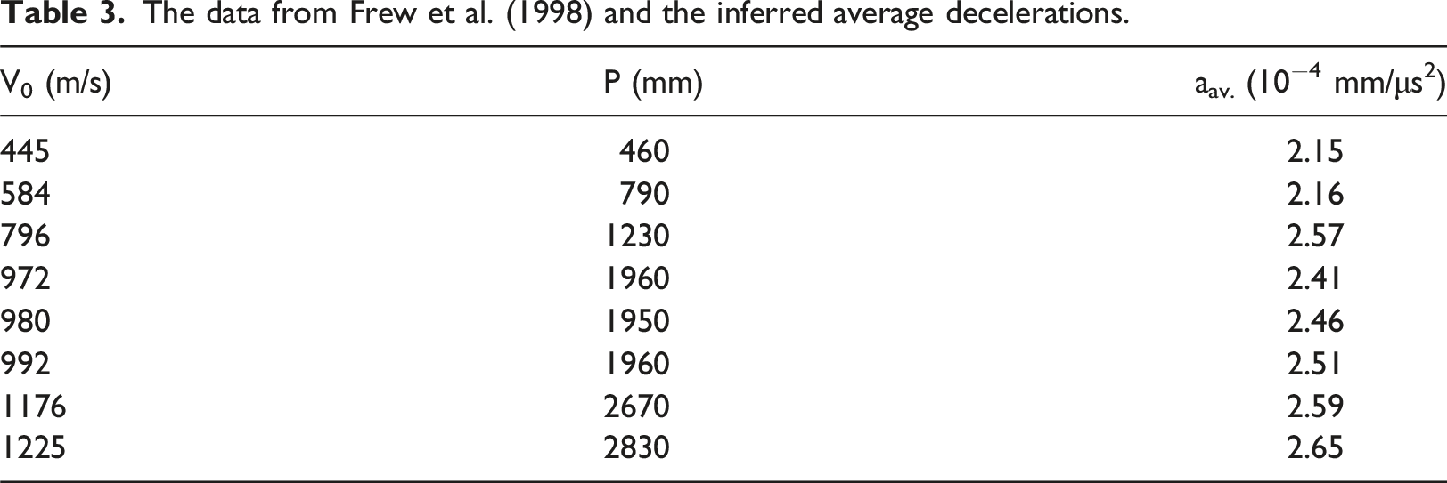
By analyzing several sets of data for concretes with different compressive strength, Rosenberg and Dekel (2010) concluded that the deep penetrations in concrete targets are governed by a constant resisting stress (Rt), which depends on the concrete’s uniaxial compressive strength (fc). For each set of data, they derived the average value of the constant resisting stress (Rt) through the relation Rt = ρpLeffaav, using the inferred decelerations from the data, namely, aav. = V02/2P. The empirical relation between the compressive strength of the concrete (fc) and its Rt value was found to be:
The relation in equation (28) was revised by Rosenberg and Kositski (2016) to include larger projectiles (D = 76 mm). They realized that the ratio between the projectile’s diameter (D) and the size of aggregates in the concrete (d) plays an important role in its resisting stress. They derived the following empirical relation for Rt in terms of fc and the ratio D/d, for projectiles having diameters in the range of D = 6-76 mm:

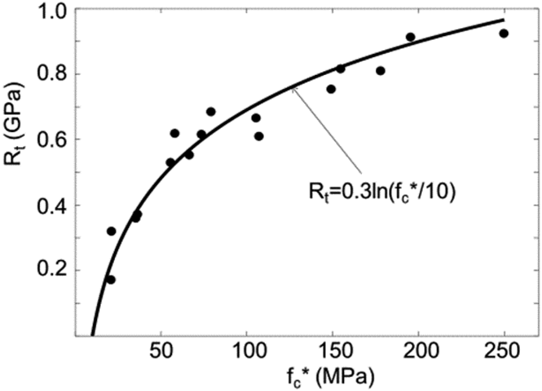
The “scaling issue” was further investigated by Rosenberg et al. (2020b) who suggested that this issue is closely related to the “size effect” in the concrete’s strength. According to this well-known effect, the compressive strength of a given concrete depends on the size of the test specimen (Ds) with which its strength is determined. These test specimens are usually cylinders with an aspect ratio of Ls/Ds = 2.0. The “size effect” is the name given to the observation that larger test specimens result in lower uniaxial compressive strength for a given concrete. As the rigid projectile is penetrating through the target it pushes aside a concrete cylinder which has a diameter like that of the projectile. This is obvious for all cases where the penetration channel has the same diameter as that of the projectile, the so-called tunneling stage. Thus, Rosenberg et al. (2020b) made the heuristic assumption that the resistance to penetration of a concrete target is determined by the strength of a concrete cylinder which has the projectile’s diameter. This means that large projectiles must push aside large concrete cylinders which, in turn, have lower compressive strengths due to the “size effect.” Using published data for the “size effect,” for the dependence of fc on Ds of various concretes, Rosenberg et al. (2020b) defined a new entity fc*(D). This is the compressive strength of a given concrete as determined with a test specimen which has the same diameter as the projectile (D). The published data for the size effect in concrete suggested the following relation for this new entity: The agreement between equation (32) and the data for various concretes and projectiles.

This approach to concrete strength explains the important results of Canfield and Clator (1966). They chose two sets of projectile/concrete pairs, which differed by a factor of 10 in their dimensions, and performed a series of penetration tests at impact velocities in the range of 300–800 m/s. To have a perfect scaling between the two sets, they reduced the aggregate size and the diameter of the steel reinforcements by a factor of 10 in the scaled-down targets. The crucial issue in their experiments was that they applied a factor of 10 for the dimensions of the test specimens (Ds), that were used to determine the unconfined compressive strengths of the two types of targets. This means that both projectile/target pairs had the same value of fc* and, hence, the same value of Rt. The outcome of this work was that a single normalized penetration curve (P/D) as a function of impact velocity, accounted for both sets of data. Thus, linear scaling behavior has been demonstrated in the terminal ballistics of concrete targets when a perfect scaling was applied for both targets and projectiles. This means that the “scaling issue” is the result of incorrect scaling in the tests, when only the projectile’s dimensions are varied. Another conclusion which can be drawn from the work of Canfield and Clator (1966) is that the concrete’s strength is practically independent of strain rates. A factor of 10 in the dimensions of the projectiles and targets means that the same factor characterizes the strain rates in these targets during penetration. The fact that Canfield and Clator (1966) found a single normalized penetration curve for both scales strongly supports the notion that concrete materials are rate independent.
The strain-rate sensitivity of concrete was further discussed by Rosenberg et al. (2018b). They compared the resisting stress obtained by a static indentation test on a concrete target, with its dynamic resisting stress as inferred from the deep penetration of the steel core of a 7.62 mm AP projectile. The measured stress–distance curve from the static indentation test is shown in Figure 19, together with the curve obtained by removing the static friction on the indenter’s shank. The corrected curve resulted in a constant resisting stress of 0.75 GPa at the deep penetration of the indenter. Using the appropriate values for the diameter and the mass of the hard steel core of the 7.62 mm projectile, together with its penetration depth of 60 mm at an impact velocity of 759 m/s, resulted in a resisting stress of Rt = 0.75 GPa, which is exactly the value obtained by the static indentation test. This fact is another indication that the resisting stresses of concrete targets are independent on the strain rate. We should note that this is a controversial issue with different views offered by various workers, as discussed by Li and Meng (2003) for example. They conclude that “the observed strain-rate sensitivity from 102 s−1 in SHPB test is a pseudo-strain-rate effect, which is caused actually by the material strength sensitivity to the hydrostatics stress due to the lateral inertia confinement.” Thus, the apparent strain-rate sensitivity of concrete is not a real material property, and it is due to an artefact in the interpretation of high-rate Kolsky-bar tests. Stress-distance profiles exerted on the conical indenter in the static test.
Another important conclusion, concerning the effect of friction, can be drawn from these experiments. Since the static and the dynamic resistance to penetration reached the same value, one can conclude that the dynamic fiction on the projectile’s shank is negligible. The effect of the dynamic friction on the projectile’s shamk during penetration, was further discussed in Rosenberg and Vayig (2021b), by examining various sets of dynamic and quasi-static data. They showed that the dynamic friction on the shanks of rigid projectiles penetrating concrete targets, is negligible. Thus, one can conclude that there is no need to implement friction forces in analytical models, nor in numerical simulations, for concrete penetration. In contrast, one can find many published works that use various friction coefficient in order to account for their data on concrete penetration.
Perforation of concrete slabs
The perforation of concrete slabs by rigid projectiles was investigated by Rosenberg and Kositski (2016). They used numerical simulations to follow the influence of the two free surfaces of the slab, to determine their extent beyond the tunneling channel where the resistance is constant. The entrance and exit phases were shown by the simulation to exert linear increase and linear decrease in the resistance, respectively, as shown schematically in Figure 20 for a concrete slab of thickness H. Clearly, the combined effect of the two phases is to reduce the slab’s effective resisting stress (Reff) to a lower value than Rt. The resisting stress in a concrete slab with the entrance phase and exit phase.
The effect of both entrance and exit phases was estimated by Rosenberg and Kositski (2016), through their numerical simulations, to reduce the concrete’s resisting stress from Rt to an effective resisting stress (Reff) according to:


These relations were shown by Rosenberg and Kositski (2016) and by Rosenberg et al. (2022) to account for many sets of data for Vbl values and for Vr (V0) curves of concrete slabs with different strengths and thicknesses. For example, Figure 21 shows the agreement between these relations and the perforation data of Hanchak et al. (1992) for two types of concretes, with fc = 48 MPa and fc = 140 MPa, impacted by CRH3 ogive-nosed steel rods. Note that the data include tests that cover a large range of impact velocities including velocities much higher than the ballistic limits, and this is also the case for other sets of data which we analyzed in the papers cited above. Test results (symbols) from Hanchak et al. (1992) and our predictions (dashed curves) for two types of concrete.
Concluding remarks
We reviewed our work on the physical mechanisms operating during the penetration and perforation of metallic and concrete targets impacted by rigid projectiles. Our approach is based on experimental data and their numerical simulations, through which we construct analytical models that follow these processes during normal and inclined impacts. These models are manifested by simple relations for the penetration depths of rigid projectiles in semi-infinite targets, and for the ballistic limit velocities of various projectile/plate pairs. The main conclusions from our work are: (1) The resisting stress (Rt) exerted by a semi-infinite metallic or concrete target on rigid projectiles, beyond a short entrance phase, is constant throughout their deep penetration. The contribution of the entrance phase to the total penetration depths of these projectiles depends on their nose shapes. (2) The constant resisting stress conjecture for metallic targets holds for impact velocities below a threshold velocity (Vcav), which marks the onset of cavitation in the target. For higher impact velocities, the inertia of the target (ρtV2) has to be added to the resisting stress. (3) The values of Rt for metallic targets depend on their dynamic compressive strength (Y) and on their elastic moduli (K and G), as well as on the projectile’s nose shape. (4) The proper value for Y to be used in numerical simulations or in analytical models, is the dynamic flow stress of the target material as measured by a Kolski-bar test at a rate of about 104 s−1 and at a strain of 0.27. (5) The values of Rt for concrete targets depend on a new entity (fc*) which we defined. This is the concrete’s uniaxial compressive strength for a test specimen which has the same diameter as the projectile. Our approach led to a simple dependence of Rt on fc* which accounts for the “scaling issue” in concrete penetration by rigid projectiles with different diameters. (6) The effective resisting stress exerted by a metallic plate (σr) or a concrete slab (Reff) on a rigid projectile, can be derived from their corresponding values for Rt and the normalized thicknesses (H/D) of these plates/slabs. (7) The friction on the projectile’s shank during penetration is negligible for concrete targets, and it has a small effect on projectiles perforating metallic plates. (8) By analyzing various penetration data, we showed that the compressive strength of concrete is insensitive to strain rates. (9) The penetration depths of rigid projectiles impacting metallic targets at a yaw angle, are governed by a non-dimensional entity: A = Rt/ρpV02. (10) The trajectory changes and the penetration depths of rigid projectiles obliquely impacting metallic targets are related to the threshold ricochet angles (αric) through simple relations. The threshold ricochet angles were found to depend on the non-dimensional parameter A.
Footnotes
Acknowledgments
We would like to thank Prof. Avi Dancygier from the Technion, for many helpful discussions over the years.
Declaration of conflicting interests
The author(s) declared no potential conflicts of interest with respect to the research, authorship, and/or publication of this article.
Funding
The author(s) received no financial support for the research, authorship, and/or publication of this article.