
Abstract
As coastal regions become increasingly susceptible to extreme wind loads and debris impact, the demand for robust, self-monitoring building envelopes has become critical. It creates an urgent imperative for advanced, resilient construction solutions. The current study presents smart composite structural insulated panels (CSIPs) embedded with piezoelectric sensors for damage localization in high-risk areas. The CSIPs comprise Aluminum face sheets positioned on both the top and bottom surfaces, sandwiching an Expanded Polystyrene (EPS) core to provide superior insulation and structural integrity. Rigorous experimental tests, including four-point flexural tests per ASTM C393 and shock load simulations, assessed mechanical properties and failure modes. A shock and impact testing simulator generated planar shock waves, with pressure profiles measured using dynamic transducers. Piezoelectric sensors embedded in the EPS core, via granular rod sensors (steel hemispheres and nylon shaft), captured Lamb waves transforming into solitary waves. Time differences of arrival (TDOA) from three non-collinear sensors enabled triangulation-based localization, validated experimentally. Real-time shock identification and impact localization are demonstrated experimentally, with predicted damage locations achieving a maximum error below 5%, indicating the suitability of these panels as a foundational technology for self-resilient coastal infrastructure. The proposed approach delivers real-time information on structural integrity, supporting improved safety and predictive maintenance for buildings and infrastructure employing CSIP systems.
Keywords
Highlights
• Introduces a novel smart Composite Structural Insulated Panel (CSIP) design that integrates granular piezoelectric sensors directly into the core for autonomous impact detection in severe weather zones. • Examines the structural performance of panels comprised of Aluminum face sheets and an Expanded Polystyrene (EPS) core, optimizing them for high insulation and mechanical robustness against shock loads. • Establishes a damage identification framework that exploits the transformation of guided Lamb waves into non-linear solitary waves to precisely triangulate impact coordinates using time-of-flight analysis. • Enables ongoing integrity assessment of smart CSIPs in harsh coastal climates via embedded health monitoring technology.
Introduction
Coastal regions globally face severe risks from catastrophic weather events, including cyclones, tornadoes, and hurricanes. The extreme wind velocities and resulting storm surges associated with these disasters frequently cause devastating flooding (Krishna et al., 2025) leading to substantial human casualties and economic loss. Such storms generate forces capable of lifting structures from their foundations, while wind-borne debris poses a critical threat to the integrity of building envelopes. For instance, the widespread destruction caused by Hurricane Katrina in 2005 resulted in damage to more than 200,000 homes (Deryugina et al., 2018).
To ensure structural safety in these vulnerable areas, design and construction practices must adhere to rigorous international standards, such as ASCE 7-10 (American Society of Civil Engineers, 2013), EN 1991-1-4.6 [Eurocode 1, 2005], ISO 4354:2009 (Bureau of Indian Standards, 2009), and various national codes (Architectural Institute of Japan, 1996, Australian/New Zealand Standard, 2011; Bureau of Indian Standards, 2015). Specific provisions for wood and timber components under wind loading are outlined in standards like ANSI/AF&PA (ANSI, 2005). Furthermore, protocols such as TAS 203-94 (TAS F, 1994) establish testing criteria for exterior building components including windows and doors subjected to cyclic wind pressure. ASCE 7-10 classifies wind-borne debris by size, distinguishing between small objects (e.g., gravel) and large missiles (e.g., framing lumber), as well as by geometry, including rod-like, plate-like, and compact forms (Wills et al., 2002; Minor, 1994). Strict impact resistance criteria are also mandated for storm shelters, with standardized testing methodologies provided by ICC 500-2014, FBC, 2010, and FEMA P-361 (Federal Emergency Management Agency, 2021; FBC, 2010; Rossiter et al., 2005).
In coastal construction, Structural Insulated Panels (SIPs) are widely utilized for both structural and non-structural applications due to their high strength and thermal efficiency. Traditional SIPs typically consist of a polymer core sandwiched between two wood-based face sheets, such as Oriented Strand Board (OSB). However, the demand for materials capable of withstanding harsh environmental conditions has driven the evolution of Composite Structural Insulated Panels (CSIPs). CSIPs function as a unified stiffened system, bonding thin, high-strength face sheets to a lightweight core. In this configuration, the face sheets resist bending stresses, while the core maintains stiffness and provides shear resistance by keeping the faces separated. Optimal material selection and adhesive bonding are critical to ensuring high stiffness-to-weight ratios and torsional rigidity (Betts et al., 2018; Mousa and Uddin, 2010; Mousa and Uddin, 2009; Mousa and Uddin, 2012).
Extensive research has characterized the mechanical performance of CSIPs under various loading conditions (Mak and Fam, 2019b; Chen and Hao, 2015; Chen and Hao, 2014; Zhu et al., 2008). For example (Vaidya et al., 2010), analyzed the response of full-scale and reduced-scale CSIP walls to high-velocity impact and compression. Several researchers (Hajzargerbashi et al., 2010; Mak and Fam, 2019a; Mak and Fam, 2019c; Jawdhari and Fam, 2020) conducted comprehensive studies on sandwich panels under thermal stress, noting that while reduced-scale specimens often failed via buckling, full-scale counterparts were prone to face sheet-core delamination. Similarly, Mousa and Uddin (Mousa and Uddin, 2012) observed global buckling in wall panels, whereas floor panels exhibited debonding on the compression side. Smakosz and Tejchman (Smakosz and Tejchman, 2013; Chen and Hao, 2014) further categorized failure modes, including shear punching and tearing. Despite these advancements, CSIPs remain susceptible to internal damage from wind-borne debris damage that often compromises structural integrity yet remains difficult to detect visually.
Consequently, the integration of Structural Health Monitoring (SHM) systems is critical for assessing post-impact integrity (Kundu, 2013). Techniques such as triangulation, utilizing Lamb waves and surface acoustic waves detected by surface-mounted sensors, have proven effective for damage localization in metallic and composite structures. Impact identification in complex, anisotropic, and heterogeneous materials has been achieved by minimizing non-linear error functions derived from time of flight of the wave data (Kundu, 2013; Shelke et al., 2011; Nasrollahi et al., 2017). For sandwich composites specifically, embedding sensors directly within the structure has emerged as a promising detection strategy. Shelke et al. (Shelke et al., 2014) introduced a method using embedded granular crystals ordered chains of spheres that leverage Hertzian contact laws for precise identification. In this approach, surface waves from an impact event are transformed into non-distortive, non-linear solitary waves at the sensor interface; these waves are then transmitted to a piezoelectric element to facilitate accurate damage localization. The smart composite structural insulated panels (CSIPs) was introduced by (Rajeev et al., 2024a) featuring embedded piezoelectric sensors for impact detection and damage localization in hurricane and tornado prone coastal regions. The study demonstrates effective shock identification and the potential for real-time structural health monitoring in self-resilient infrastructure.
The present study builds upon and extends this foundational work by developing an advanced CSIP configuration utilizing Aluminum face sheets sandwiching an Expanded Polystyrene (EPS) core, specifically engineered to withstand extreme coastal conditions. The study provides a systematic expansion of current knowledge through experimental analysis of shock response and collapse modes under four-point bending and in-panel compression tests. By integrating structural health monitoring capabilities, these smart CSIPs facilitate continuous assessment of responses to environmental stressors, ultimately improving the durability and lifespan of coastal buildings. The experimental validation of shock identification and localization highlights the significant potential of these smart CSIPs in advancing self-resilient infrastructure for vulnerable coastal areas.
Research significance
Coastal zones globally are increasingly exposed by catastrophic weather events, including cyclones, hurricanes, and tornadoes. The high-velocity winds and storm surges associated with these phenomena frequently result in severe flooding and massive destruction of property and life, as exemplified by the devastation of over 200,000 homes during Hurricane Katrina in 2005. To mitigate these risks, the design and construction of coastal infrastructure are governed by rigorous international frameworks, such as ASCE 7-10, EN 1991-1-4.6, ISO 4354:2009, and various regional standards including National Research Council of Canada, 2005 and IS 875 (Part 3). These codes provide essential guidelines for ensuring materials and designs can withstand extreme wind loads and the impact of wind-borne debris.
While standard Structural Insulated Panels (SIPs) are widely utilized for their thermal and structural benefits. Composite Structural Insulated Panels (CSIPs) have evolved as a more robust alternative, featuring high-strength thin face sheets bonded to a lightweight core. Despite extensive research into their mechanical behavior under compressive and impact loading, CSIPs remain vulnerable to internal damage from impact events damage that is often invisible yet critical to structural safety. This vulnerability emphasizes the urgent need for integrated Structural Health Monitoring (SHM) solutions.
Embedding piezoelectric shock sensors within CSIPs offers a proactive SHM strategy, enabling the detection and localization of shock waves to identify damage early. This approach represents a critical advancement in creating structures capable of self-diagnosis. Consequently, this study focuses on the development of smart CSIPs using Aluminum face sheets specifically engineered for harsh coastal environments. Through systematic experimental analysis, the research investigates the shock response and failure mechanisms of these panels under various loading scenarios. By validating the capability for real-time shock identification and localization, this work demonstrates the potential of smart CSIPs as a foundational element in the next generation of self-resilient, predictive coastal infrastructure.
Experimental details
Materials and methods
This study investigates the performance of smart composite structural insulated panels (CSIPs) composed of Aluminum face sheets and an Expanded Polystyrene (EPS) core. The Aluminum face sheets possess a thickness of 1.5 mm, while the EPS core is 86 mm thick, selected to optimize the panel’s stiffness to weight ratio and thermal efficiency. The integrated sensor system utilizes chrome steel for the hemispheres and nylon for the sensor shaft. For analytical modeling purposes, all constituent materials are idealized as isotropic, defined by their respective density, elastic modulus, and Poisson’s ratio. For the EPS core specifically, this assumption is justified on the basis of the density employed in this study (16 kg/m3), at which the ratio of in-plane to out-of-plane compressive modulus reported in the literature typically falls within the range of 0.85–1.10, indicating near-isotropic mechanical behavior. The degree of directional anisotropy introduced during the steam-chest molding manufacturing process is most pronounced at densities below 12 kg/m3 and diminishes progressively with increasing density, rendering the isotropic idealization a reasonable and well-supported approximation at the density level employed here. Furthermore, the EPS core in the present CSIP configuration functions primarily as a shear-transfer medium rather than a primary bending load-carrying component, with the high-stiffness Aluminum face sheets (Young’s modulus: 71 GPa) dominating the flexural response of the composite panel. The error introduced by the isotropic assumption in computing core shear stress distributions is therefore considered small relative to the overall structural response. It is acknowledged, however, that a fully rigorous treatment of EPS mechanical behavior particularly in the context of failure prediction involving shear-dominated cracking would benefit from orthotropic material characterization, and this is identified as a direction for future investigation. These materials were specifically chosen for their mechanical robustness and suitability for deploying embedded piezoelectric sensor networks within coastal infrastructure. The key mechanical properties for each component are detailed in the following subsections.
Mechanical properties of constituent materials
Expanded polystyrene (EPS)
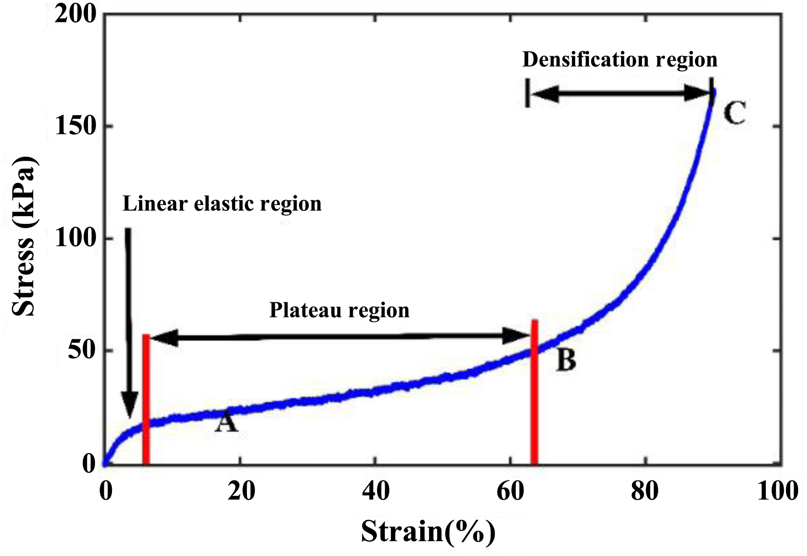
Expanded Polystyrene (EPS) is extensively employed across diverse engineering applications due to its favourable combination of light weight, superior thermal insulation, moisture resistance, durability, acoustic damping characteristics, and minimal thermal conductivity. Its adoption in civil infrastructure has grown substantially, particularly as a core material in structural insulated panels (SIPs). To characterize the mechanical behavior of the EPS core utilized in this study, quasi-static, strain-controlled, unconfined uniaxial compression tests were performed on prismatic specimens measuring 100 mm × 100 mm × 43 mm. Testing was conducted in accordance with ASTM D695-15 at a constant displacement rate of 2 mm/min. Three tests were performed to ensure statistical reliability. The progressive deformation stages observed during compression are illustrated in Figure 1, while the corresponding stress-strain response is presented in Figure 2. Consistent with established cellular mechanics theory, the constitutive behavior exhibited three distinct regimes (Horvath, 1994) i.e., a linear elastic zone (1% to 2% strain, origin to point A), a plateau region (2% to 60% strain, A to B) characterized by relatively constant stress during cell collapse, and a densification zone (beyond 60% strain, B to C) marked by rapid strain hardening due to compaction of the cellular structure. Different stages of compression testing of EPS (a) undeformed stage, (b) 60% compression, and (c) 85% compression (Rajeev et al., 2024a). Stress-strain curve for EPS under compression testing (Rajeev et al., 2024a).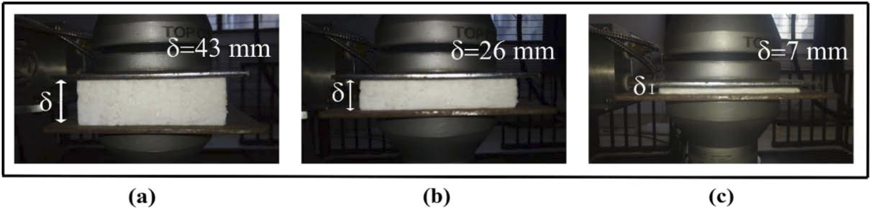
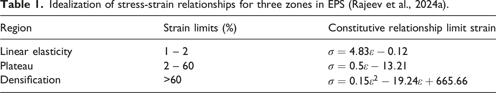
Idealization of stress-strain relationships for three zones in EPS (Rajeev et al., 2024a).
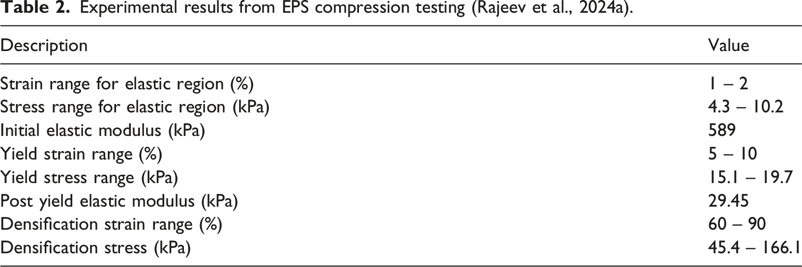
Experimental results from EPS compression testing (Rajeev et al., 2024a).
Statistical validation of the fitted equations was performed using the coefficient of determination (R-Squared values), with all values exceeding 0.9, thereby confirming a high degree of correlation between the idealized models and the experimental data.
Aluminum face sheet
Aluminum alloys are extensively utilized in modern structural engineering, particularly for lightweight building envelopes, due to their exceptional strength to weight ratio, ductility, and corrosion resistance. Unlike brittle cementitious composites like plywood or oriented strand boards (OSB), fibre cement board (FCB), Aluminum face sheets provide significant energy absorption capacity, making them highly suitable for coastal structures exposed to dynamic wind loads and impact from waterborne or airborne debris.
Aluminum alloy AL-5052-H32 sheets were employed as the face sheet material for the CSIP specimens in this study. This alloy offers excellent corrosion resistance and moderate strength, making it particularly suitable for coastal structural applications where exposure to marine environments is anticipated. The face sheets, each measuring 1.5 mm in thickness, were bonded to the upper and lower surfaces of the expanded polystyrene core to provide enhanced flexural stiffness and impact energy absorption capacity.
To characterize the constitutive mechanical behavior of the face sheet material, quasi-static tensile testing was performed using an INSTRON universal testing machine under displacement control at a constant strain rate of 1 mm/min. Specimen geometry adhered to ASTM E8/E8M:2016 standards for metallic materials, as illustrated in Figure 3(a). Three replicate specimens were tested under controlled laboratory conditions to ensure statistical reliability and reproducibility of results. The force-displacement response was recorded continuously and subsequently converted to engineering stress-strain curves, with a representative response presented in Figure 3(b). Quasi-static tensile testing of Aluminum face sheet AL-5052 H32: (a) sketch of sample geometry as per ASTM E8/E8M:2016, and (b) typical stress-strain curve (Rajeev et al., 2020).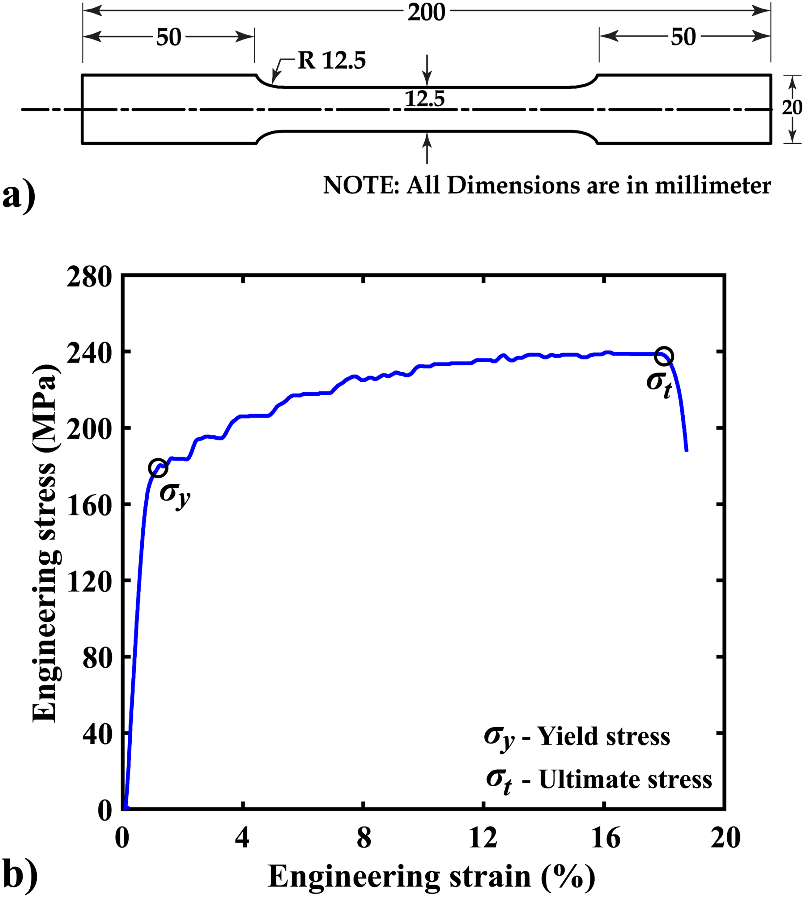
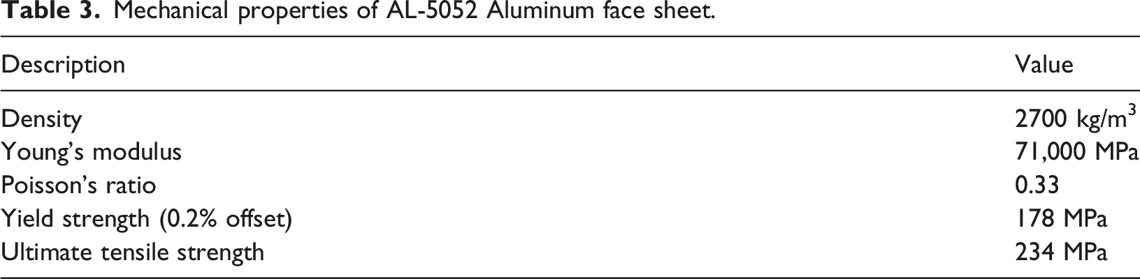
Mechanical properties of AL-5052 Aluminum face sheet.
Fabrication of CSIP specimens
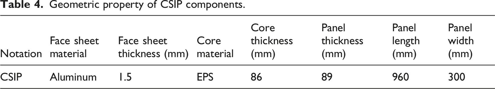
This study investigated the performance of CSIP specimens constructed from two Aluminum face sheets laminated to an EPS core. The fabrication process began with the preparation of the EPS core, where the surfaces were planarized using an electrically heated wire cutter to ensure uniform thickness and optimal surface roughness for bonding. The Aluminum face sheets were subsequently bonded to the core using a high-strength epoxy adhesive. To ensure consistent adhesion and a uniform bond line thickness, a distributed static load was applied across the entire panel assembly during the curing phase. The resulting fabricated CSIP specimen is illustrated in Figure 4, while the geometric specifications of the individual components are detailed in Table 4. CSIP specimen with Aluminum face sheets and EPS core. Geometric property of CSIP components.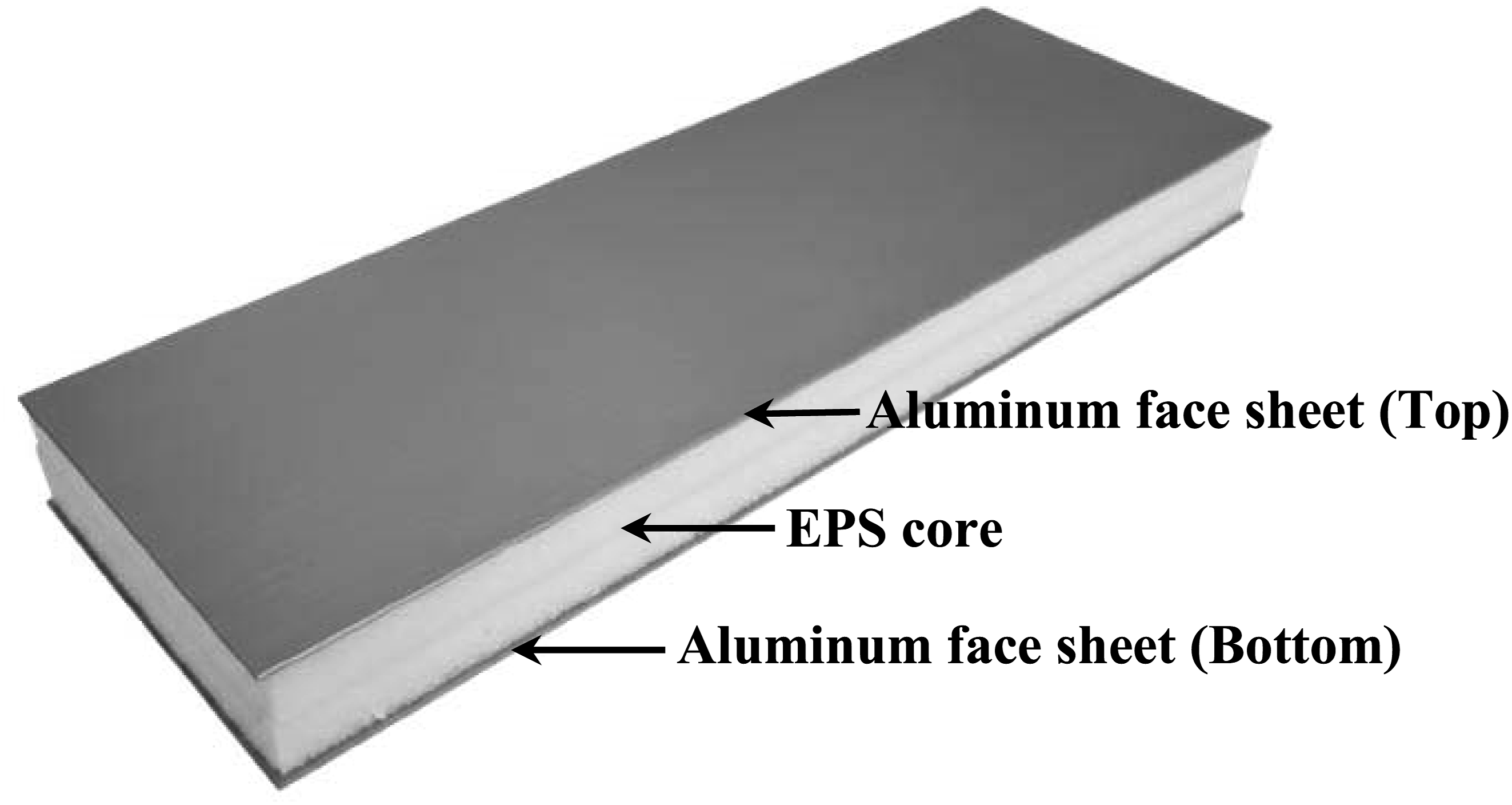
Flexural test of CSIP specimens
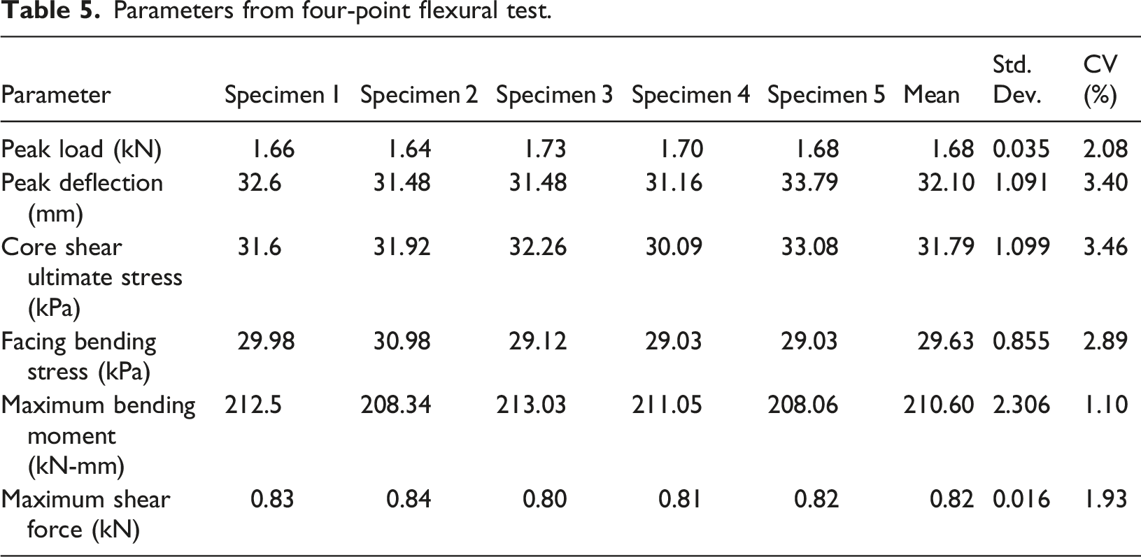
To evaluate the structural performance of the CSIPs, a series of four-point bending tests were performed in accordance with ASTM C393 standards. The experiments were performed using a Universal Testing Machine (Model number: UTE-20, FIE) with 200 kN capacity under displacement control at a rate of 1 mm/min. Statistical reliability was ensured by testing five replicate specimens. All five specimen values were lies within ±5% consistent with the well-controlled fabrication procedure described in Section 3.3. The coefficient of variation (CV) across all parameters ranges from 1.10% to 3.46%, confirming excellent experimental repeatability. These low CV values are physically justified by the uniform EPS core planarization, consistent epoxy bond-line application, and distributed curing load procedure employed during fabrication. The panels were simply supported with a clear span of 960 mm, featuring a 100 mm overhang at each end. The loading span was set to one-third of the support span to establish a region of constant bending moment.
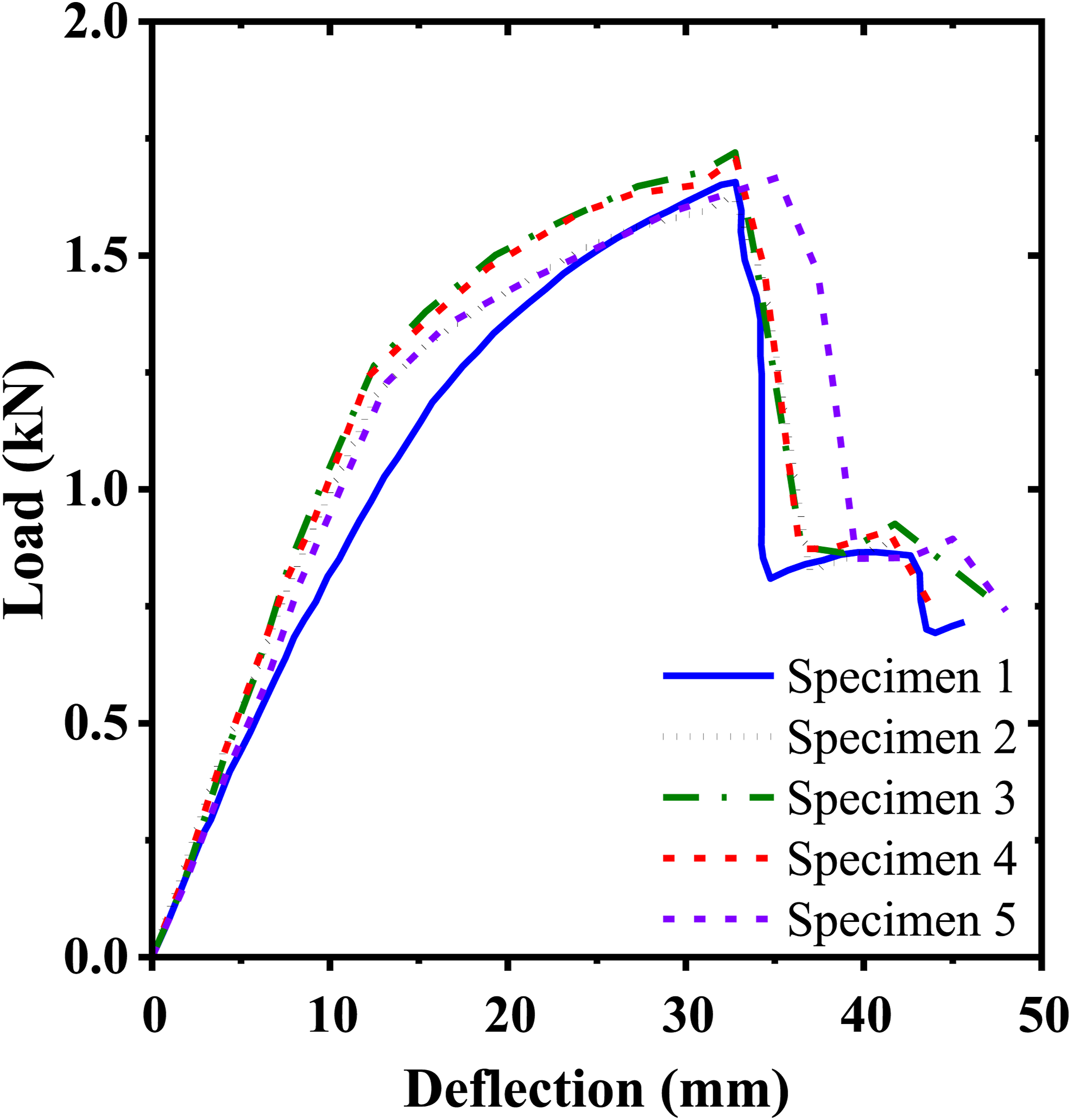
CSIP specimens exhibited primary failure due to shear-dominated debonding at the end supports, as illustrated in Figure 5. The load-deflection response is demonstrated in Figure 6. Initially it exhibits linear elastic behavior up to 1.2 kN, achieving a peak load of 1.66 kN before a sudden drop triggered by excessive deformation in the compliant EPS core, which compromised the overall panel stiffness. Failure mode of CSIP under four-point flexural test. Load deflection curves for CSIP (All Specimens).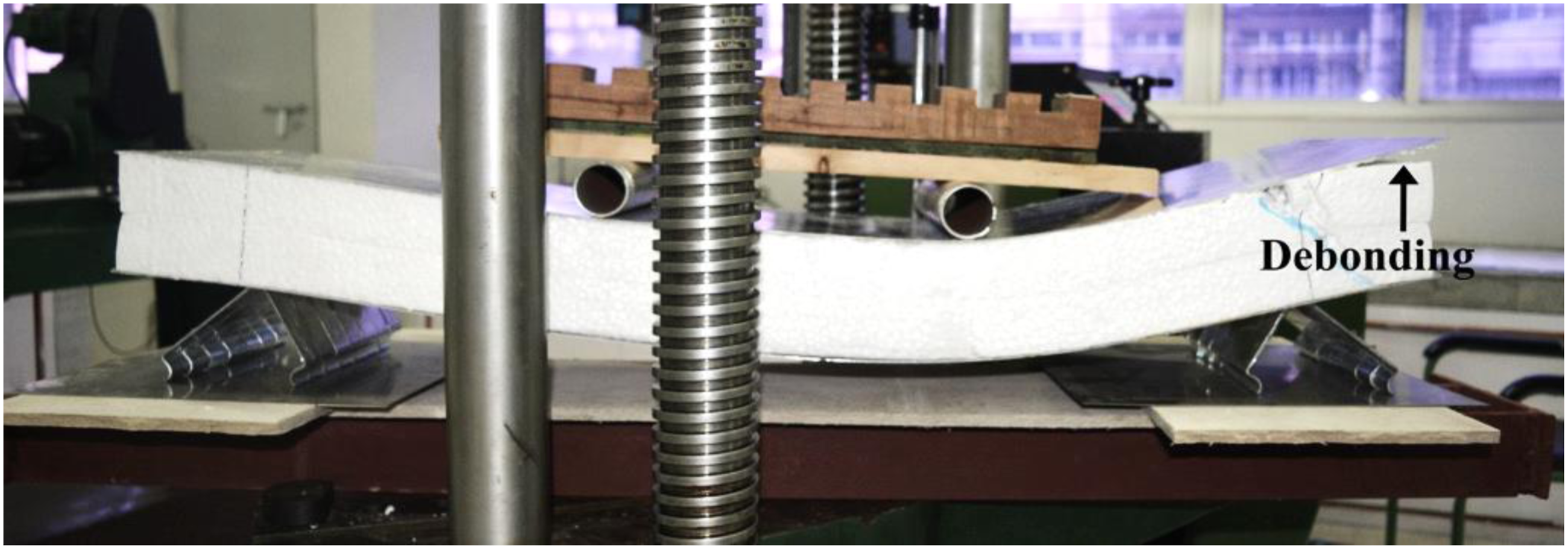
While the ductile Aluminum face sheets were able to accommodate large bending deformations, the compliant EPS core could not sustain the imposed curvature, leading to localized damage initiation within the core rather than in the skins. A diagonal shear crack originated at the top of the EPS core and propagated toward the bottom face sheet, forming a 45 mm wide fracture inclined at about 42° to the horizontal, associated by debonding region extending 171 mm near the support.
Parameters from four-point flexural test.
It is noted that the embedded piezoelectric sensor network was not connected to the data acquisition system during the four-point flexural tests reported in this section. The flexural characterization presented here serves exclusively to establish the baseline mechanical behavior including bending stiffness, peak load capacity, failure mode, and constitutive response of the CSIP configuration under quasi-static loading conditions per ASTM C393. The present study is primarily focused on the dynamic shock and impact loading scenarios characteristic of tornado, hurricane, and cyclone events threatening coastal infrastructure, for which the smart CSIP sensor network is fully instrumented, validated, and demonstrated in Sections 4 and 5. The integration of real-time piezoelectric sensor monitoring during quasi-static flexural failure testing enabling acoustic emission-based detection and localization of shear crack initiation, crack propagation, and face sheet–core debonding events constitutes a distinct and valuable research objective that falls outside the defined scope of the present investigation and is identified as a priority direction for future work.
Shock loading analysis of CSIPs
Fabrication of smart CSIP specimens
To develop smart CSIPs capable of resilient performance under shock loading, a novel sensor integration strategy was implemented. The assembly began by precision drilling the EPS core at three pre-determined coordinates to accommodate the granular rod sensors. Each sensor comprises a cylindrical nylon shaft (length: 66 mm; diameter: 20 mm) with chrome steel hemispheres (diameter: 20 mm) bonded to both planar end surfaces. The nylon component possesses a density of 1150 kg/m3, elastic modulus of 3350 MPa, and Poisson’s ratio of 0.4, while the steel hemispheres are characterized by a density of 7850 kg/m3, Young’s modulus of 200 GPa, and Poisson’s ratio of 0.3.
To ensure consistent Hertzian contact pre-load across all three embedded sensor positions, several fabrication controls were implemented. The EPS core was drilled using a single fixed drill bit diameter of 20 mm matched precisely to the sensor shaft diameter at all three sensor coordinates, ensuring identical cavity geometry throughout. Each sensor assembly was fabricated to a uniform total length of 88 mm, which, given the panel thickness of 89 mm, produces a deliberate geometric interference of 1 mm upon panel assembly. This dimensional interference passively generates a consistent compressive pre-load at both the top and bottom hemisphere–face sheet contact interfaces at all three sensor locations, irrespective of their in-plane position. Furthermore, a distributed static compressive load was applied uniformly across the entire panel surface during the epoxy curing phase, ensuring that the Aluminum face sheets were pressed against the hemispheric sensor surfaces with consistent force per unit area across all sensor positions simultaneously. Combined with the use of identical material batch and geometric specifications for all three sensor assemblies ensuring nominally equal Hertzian contact stiffness (kH) throughout these measures collectively guarantee that the contact pre-load is reproducible and consistent across the full sensor network, thereby preserving the integrity of the TDOA-based localization algorithm.
The sensors were positioned such that the convex spherical surfaces of the hemispheres maintained precise Hertzian point contact with the interior surfaces of both Aluminum face sheets, enabling efficient mechanical wave transmission across the material interface. Final panel assembly involved bonding the Aluminum skins to the sensor embedded EPS core using high-strength epoxy adhesive. Uniform bond-line thickness and void-free adhesion were ensured by applying a distributed static compressive load across the entire panel during the epoxy curing cycle.
The primary function of these sensors is to capture and transduce solitary wave signals generated by shock events for subsequent impact localization. It is achieved through PZT 840 series Piezo-electric ceramic discs (diameter: 18 mm; thickness: 1 mm) integrated at the planar interface between each hemisphere and the nylon shaft. These discs were bonded using epoxy at the planar interface between the nylon shaft and the steel hemisphere, with Kapton polyimide tape providing electrical insulation. The electrodes on the upper surface of the PZT discs were then wired to an oscilloscope for real-time signal/data acquisition.
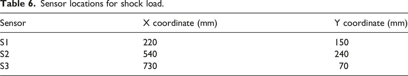
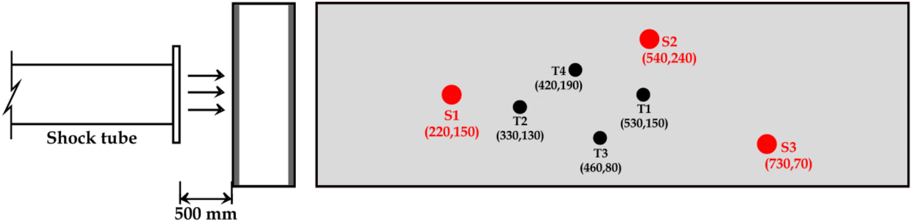
Each complete sensor assembly has a total length of 88 mm and a mass of 56.7 g. The total mass addition of the three-sensor network is estimated at 170.1 g, representing approximately 6.2% of the total panel self-weight. While this addition is considered modest based on the geometric area ratio of sensor cross-sections relative to the panel cross-section (approximately 0.12% per sensor), it is acknowledged that the claim regarding negligible structural impact of sensor integration requires direct experimental substantiation through comparative mechanical testing of sensor-embedded smart CSIP specimens against conventional baseline CSIP specimens under identical four-point bending conditions. Such comparative testing was not conducted in the current experimental program and is recognized as a limitation of the present study. A direct experimental comparison between smart CSIP and baseline CSIP specimens under four-point bending loading is therefore identified as a necessary validation step and designated as a priority direction for future experimental investigation. A schematic diagram detailing the sensor configuration and its integration within the panel is presented in Figure 7, while the precise embedment coordinates are listed in Table 6. Schematic view of Smart-CSIP with enlarged view of the sensor (Rajeev et al., 2024a). Sensor locations for shock load.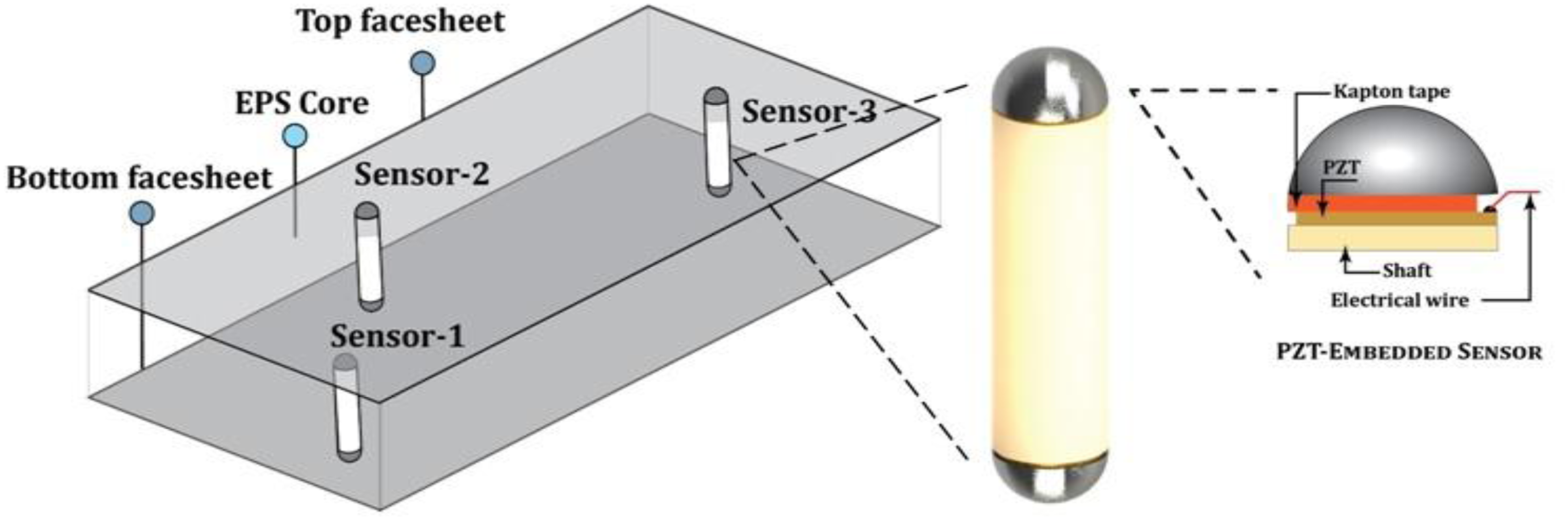
Shock load and data acquisition
The dynamic shock loading was applied to the CSIP specimens using the shock and impact testing simulator (Rajeev et al., 2024b), which generates planar shock waves with controlled pressure-time characteristics. The test specimens were rigidly clamped to a steel reaction frame using C-clamps to ensure full boundary constraint. They are positioned at a standoff distance of 500 mm from the shock tube exit plane, as depicted in Figure 8. The schematic view of the longitudinal section of the set-up is shown in Figure 9. A single-layer matt paper diaphragm was employed consistently for all experimental trials to maintain reproducible burst pressure conditions. To ensure statistical reliability and account for variability in shock propagation, three replicate tests were conducted for each arbitrary point of impact location. Experimental set up for shock tube with test specimen. Schematic diagram with the arbitrary load and sensor locations (Rajeev et al., 2024a).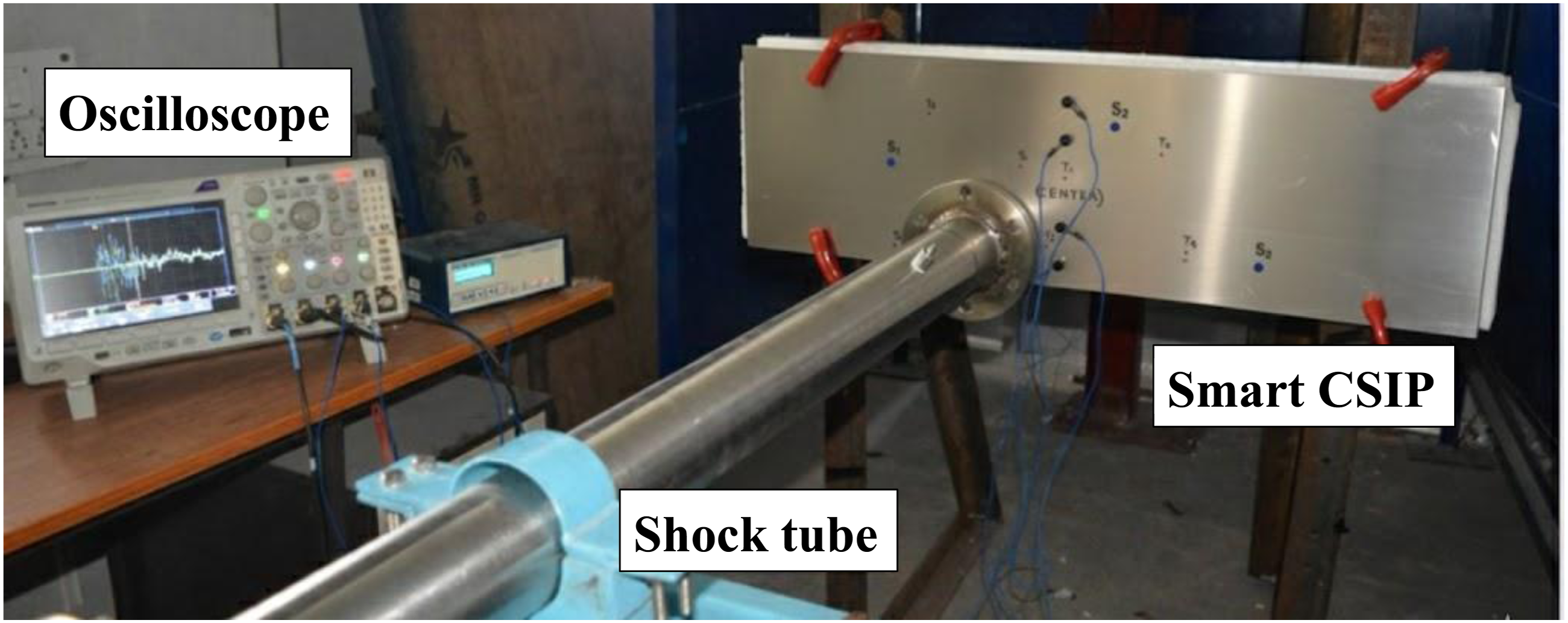
The incident shock wave pressure history was captured using dynamic ICP pressure transducers (PCB Piezotronics Model 113B22) installed at two axial locations separated by 700 mm along the shock tube length. This dual-sensor configuration enabled validation of shock wave velocity and pressure decay characteristics. The pressure profile due to one matt paper at two points within the shock tube is shown in Figure 10. The pressure-time histories recorded at the two transducer stations are analyzed to extract the key shock wave characterization parameters essential for complete description of the dynamic loading environment. From the pressure profiles presented in Figure 10, the peak incident overpressure at the upstream station (3.1 m from the diaphragm) is approximately 65–70 kPa above ambient atmospheric pressure, attenuating to approximately 60-65 kPa at the downstream station (3.8 m), reflecting viscous boundary layer losses and natural pressure decay over the 700 mm inter-transducer separation distance. The shock front rise time defined as the time interval between the undisturbed ambient pressure and the peak overpressure is approximately 0.1-0.2 ms, consistent with the near-discontinuous pressure jump characteristic of planar shock waves generated by matt paper diaphragm burst, and confirming that the loading acts as a high-intensity impulsive event rather than a quasi-static pressure application. The positive phase duration defined as the time interval between shock front arrival and return of overpressure to ambient conditions is approximately 0.8-1.0 ms at the downstream station, characterizing the loading as a short-duration, high-intensity impulsive event consistent with the weak shock regime. From the measured shock front arrival time difference between the two transducer stations, the shock wave propagation velocity is estimated at approximately 368 m/s, corresponding to a Mach number of approximately Shock wave pressure profile of one matt paper at distinct points in the driven section and at the exit of the shock tube kPa (Rajeev et al., 2024a).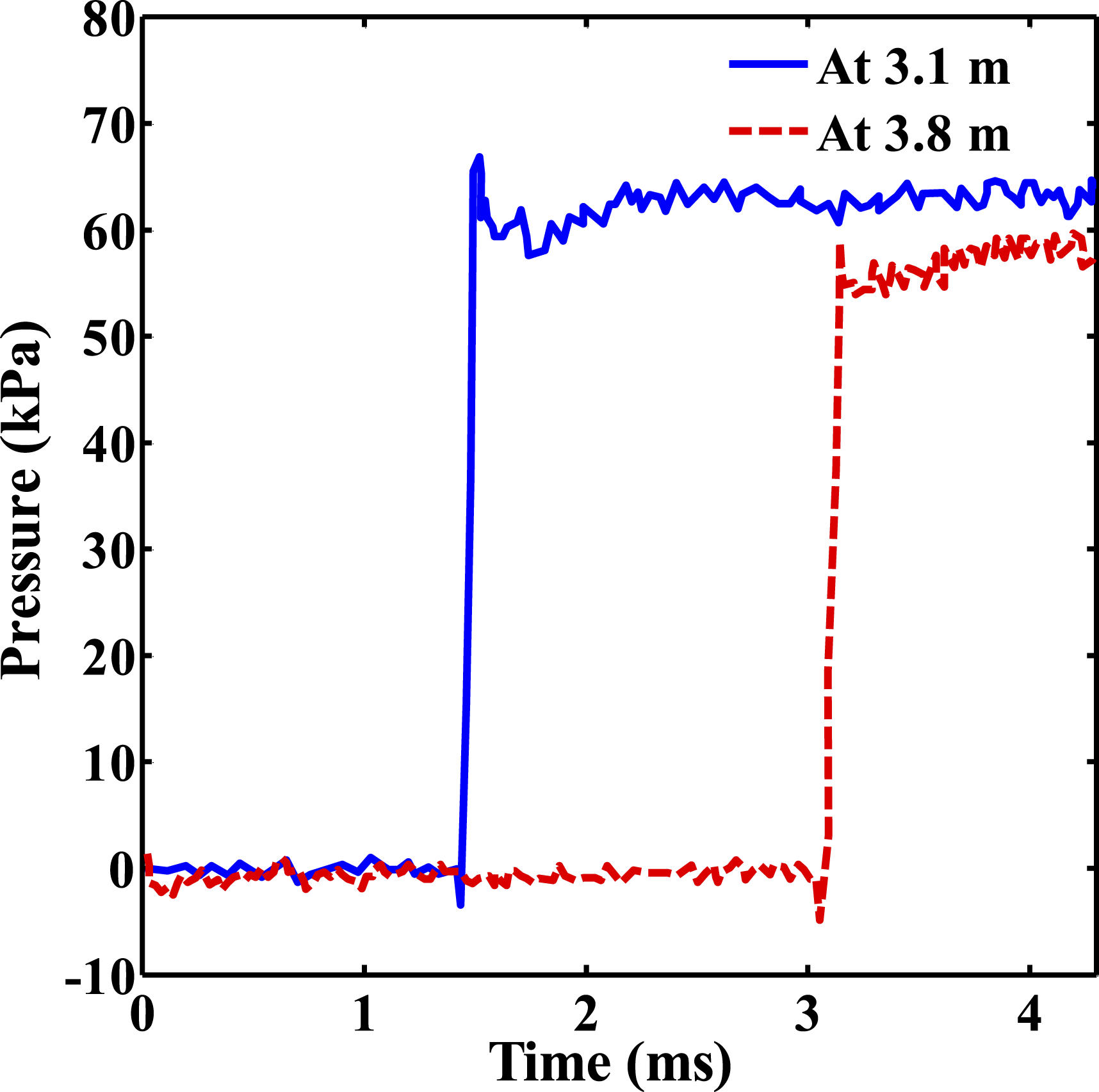
For signal transmission, the piezoelectric ceramic discs (PZTs) integrated into the three smart sensors were interfaced with the data acquisition system using low-noise alligator clips connected to triaxial cables. Simultaneous data capture from both the upper and lower PZT elements of each sensor was achieved using a Tektronix Mixed Domain Oscilloscope (MDO-3024), configured with a 200 MHz bandwidth and a maximum sampling rate of 2.5 GS/s. Additionally, the dynamic acceleration response of the panel was recorded using high-sensitivity quartz shear accelerometers (PCB ICP 352C33), which feature a sensitivity of 100 mV/g and an operating frequency range of 0.5 to 10 kHz.
Lamb wave velocity parameters
The Lamb wave velocity in the Aluminum face sheet is governed by the dispersive relationship between wave frequency, plate thickness, and material elastic properties. For the fundamental antisymmetric (A0) and symmetric (S0) Lamb wave modes propagating in an isotropic Aluminum plate of thickness h = 1.5 mm, the phase velocities are functions of the frequency-thickness product (f·h) and the material properties Young’s modulus E = 71 GPa, Poisson’s ratio
In the low frequency-thickness regime relevant to the present study, the dominant frequency content of the shock-induced Lamb wave signal is below the first cutoff frequency of higher-order modes, the 
Substituting the material properties of AL-5052-H32:
This theoretical value represents the group velocity of the
Solitary wave velocities (
and
)
The solitary wave velocity through the steel hemisphere (
The solitary wave velocity through the nylon shaft (
It is noted that the Aluminum alloy AL-5052-H32, in its wrought and strain-hardened condition, exhibits a mild crystallographic rolling texture that introduces a directional variation in Lamb wave velocity of typically less than 3% between the rolling and transverse directions a level of anisotropy that is small relative to the dominant sources of TDOA measurement uncertainty and is quantitatively assessed in the sensitivity analysis of Section 5.1. For the laboratory conditions under which all experiments were conducted at a controlled ambient temperature of approximately 20-25°C temperature-induced velocity variation is negligible. For field deployment in coastal environments spanning a service temperature range of −10°C to +40°C, the temperature coefficient of Young’s modulus for Aluminum alloys (approximately −0.04 GPa/°C) produces a maximum velocity variation of approximately 1.4% over this range, for which periodic recalibration or real-time temperature-based velocity correction is recommended for precision-critical applications.
Wave speed calibration procedure
To provide independent experimental verification of the theoretically derived wave velocity parameters employed in the localization algorithm, a pencil-lead break (PLB) calibration procedure per ASTM E976 is proposed for implementation in future experimental campaigns. In this procedure, a 0.5 mm, 2H pencil lead is fractured at known positions on the aluminum face sheet surface at measured distances from each of the three embedded sensors. The time of first arrival of the S0 Lamb wave mode at each sensor is extracted from the PZT voltage-time records using a fixed amplitude threshold detection algorithm, and the experimental group velocity is computed as:
Experimental findings from shock load on CSIP
This section presents the dynamic response characteristics of smart CSIP specimens subjected to planar shock wave excitation at arbitrary surface coordinates. Upon impact of the shock front with the top Aluminum face sheet, elastic guided waves are generated and propagate within the plate thickness according to classical Lamb wave theory. These flexural and extensional wave modes travel radially outward from the impact epicenter through the face sheet material until encountering the embedded hemispheric sensors. At the interface between the Aluminum face sheet and the curved steel hemisphere surface, mechanical contact is governed by Hertzian contact mechanics, facilitating efficient energy transfer across the dissimilar material boundary. As the guided waves reach this interface, they undergo modal conversion, transforming into highly localized nonlinear solitary waves that propagate through the granular sensor assembly. The mechanical strain induced by these solitary waves is subsequently transduced into electrical voltage signals via the direct piezoelectric effect in the embedded PZT ceramic discs. Voltage-time histories were recorded simultaneously from the three spatially distributed sensors for each arbitrary shock application point. Experiments concerning impulse detection was conducted on CSIP comprising of Aluminum face sheet. All acquired waveforms encompassing both guided wave and solitary wave components were post-processed using MATLAB (R2019a) environment executed on a workstation equipped with an Intel Xeon E5-2620v3 processor, 16 GB RAM, and NVIDIA Quadro K620 GPU for accelerated computational operations.
For shock loading at test location T1, representative transient voltage responses measured at the top and bottom PZT interfaces of Sensors 1 - 3 are shown in Figure 11(a) and (b), respectively. These waveforms exhibit characteristic arrival time differences and amplitude variations that encode the geometric information necessary for triangulation-based impact localization. Transient response in CSIP for the shock load at location T1 acquired for sensors 1, 2 & 3 at (a) Top sensor, and (b) Bottom sensor.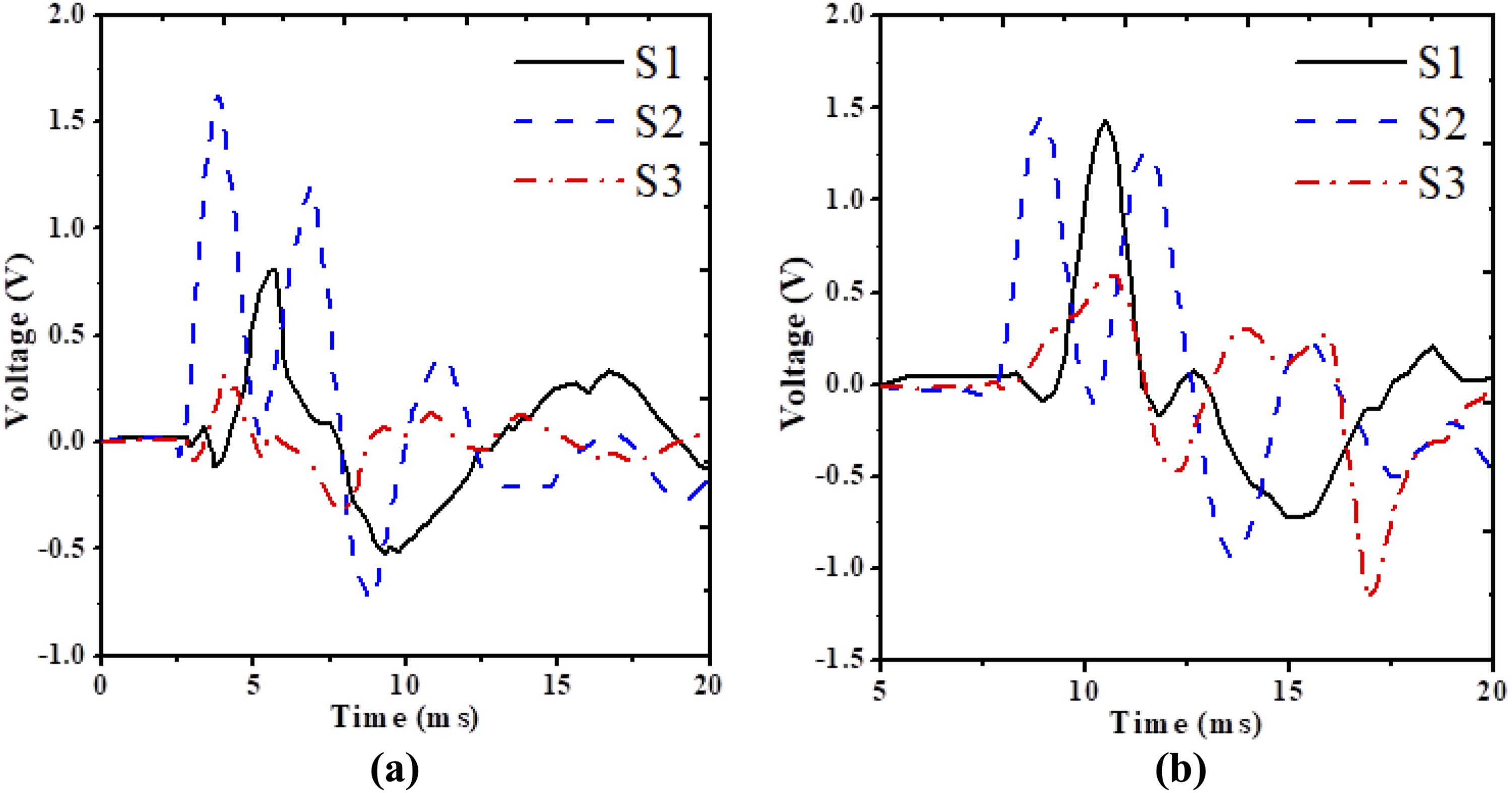
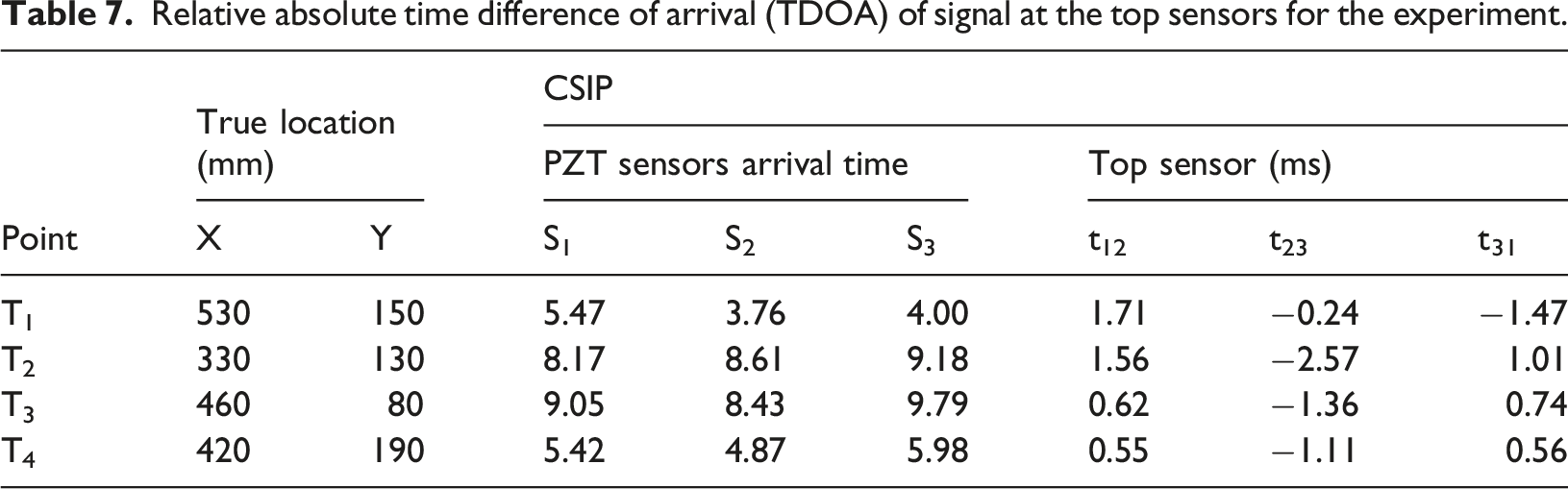
Relative absolute time difference of arrival (TDOA) of signal at the top sensors for the experiment.
Sensitivity analysis of wave velocity parameter uncertainty on localization accuracy
Sensitivity analysis of wave velocity parameter uncertainty
The robustness of the TDOA-based localization algorithm to uncertainty in the wave velocity parameter 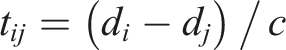
For the sensor geometry employed in the present study with typical sensor separations of 300-400 mm and source-to-sensor distances of 200-500 mm a 1% uncertainty in 
This TDOA uncertainty propagates into a source location uncertainty estimated as:
representing approximately
Modified objective function and identification of damage location
Damage localization employs the time difference of arrival (TDOA) analysis of guided Lamb waves in the face sheet and solitary waves in the granular sensors, measured at a minimum of three non-collinear hemispherical sensors. These waveforms are captured at the top and bottom hemispheric sensors embedded in the CSIP core, enabling bidirectional examination of the panel. The impact location is then estimated by minimizing an objective function derived from classical triangulation principles, in which predicted time differences based on candidate source coordinates and known wave velocities are matched to the experimentally measured values. They were developed from adapting established acoustic emission methodologies for isotropic and anisotropic plate structures (Tobias, 1976; Kundu et al., 2009).
The wave velocity parameters employed in the present localization framework, including the Lamb wave velocity in the Aluminum face sheets and the solitary wave velocity components associated with the granular sensor assembly, were adopted following the methodology reported in (Rajeev et al., 2024a; Kundu et al., 2009; Shelke et al., 2014) wherein the foundational TDOA triangulation framework, wave velocity calibration, and baseline localization accuracy for a GFRP faced EPS core CSIP configuration were first validated experimentally. That study provides detailed theoretical derivation, experimental calibration, directional velocity assessment for AL-5052-H32 Aluminum face sheets, and sensitivity evaluation of localization accuracy with respect to velocity uncertainty. Therefore, only the modified localization formulation used in the present study is presented herein, while the complete parameter justification is referred to the earlier publication for conciseness. The present study extends this framework to an Aluminum faced CSIP configuration subjected to planar shock wave excitation, demonstrating the generalizability of the approach across different face sheet material systems and loading conditions.
The principal steps in objective function formulation for shock-induced damage location is outlined below.
Let the shock impact location on the top face sheet of the CSIP be designated as
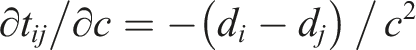
The Euclidean distances between the location of loading and each sensor are calculated using equation (1),


The above expression accounts for the combined propagation time of Lamb waves through the top face sheet and solitary waves through the embedded granular cylindrical sensor within the CSIP core. The time difference of arrival (TDOA) at the top sensor incorporates both the Lamb wave travel time across the Aluminum face sheet and solitary wave transmission through the top steel hemisphere. The TDOA for the transformed signal at the top sensor is given by:

Since the nylon shaft transit time 
The time difference of arrival (TDOA) values between any two bottom sensors can be expressed as:
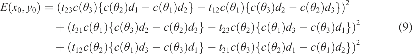
The objective function or error function can be expressed by summation of the square of the residue of the time ratios of any two sensors. To ensure unbiased localization towards any particular sensor combination, all three signal arrival measurements from the three sensor locations are incorporated. The modified error function for bottom sensors is thus expressed as: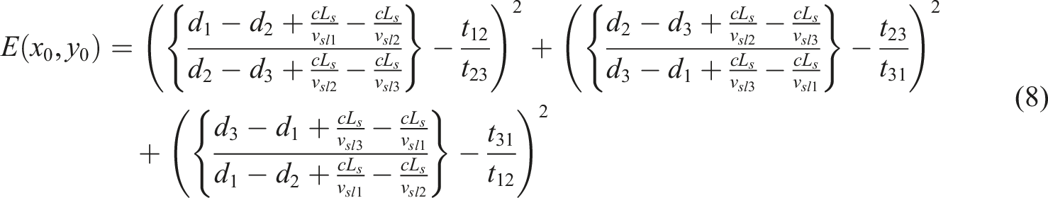
Relative absolute time difference of arrival (TDOA) of signal at the bottom sensors for the experiment.
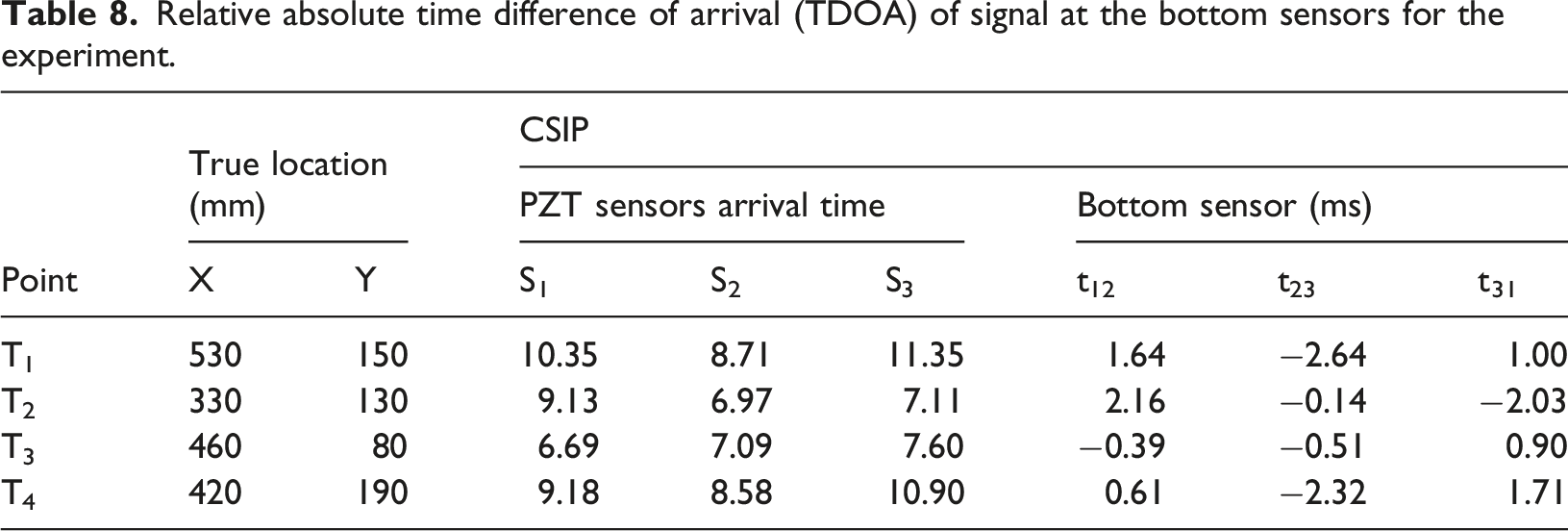
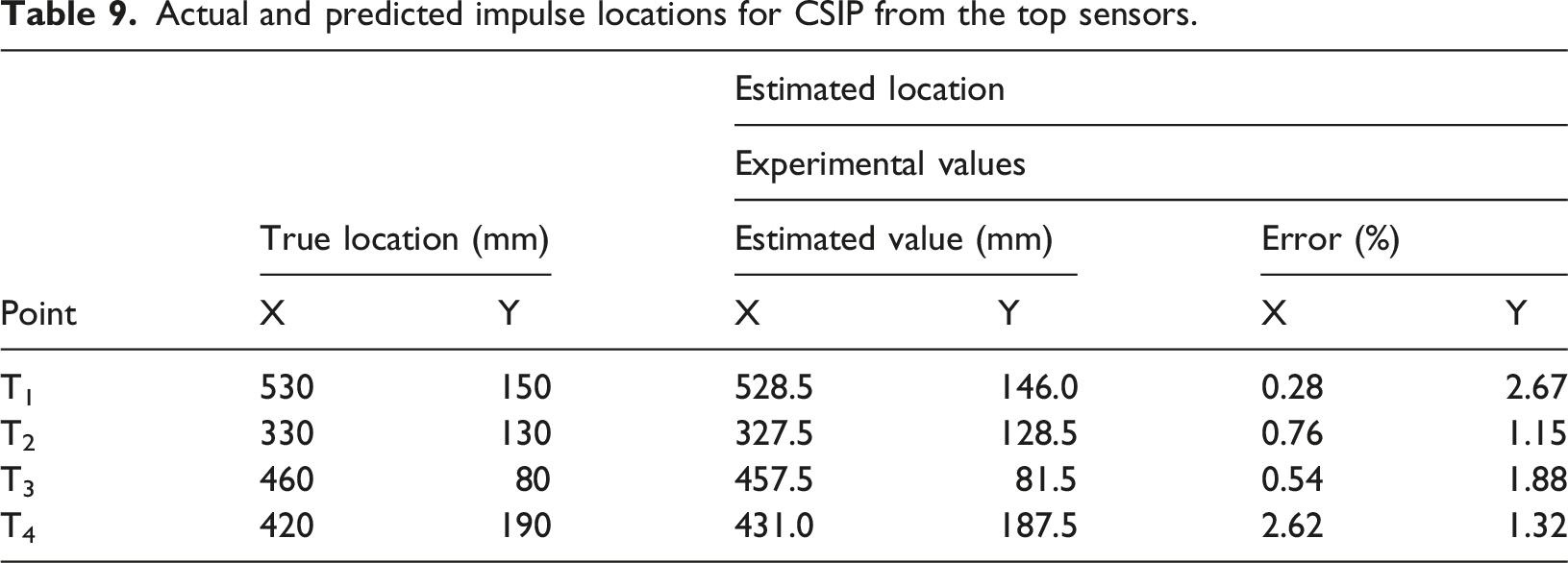
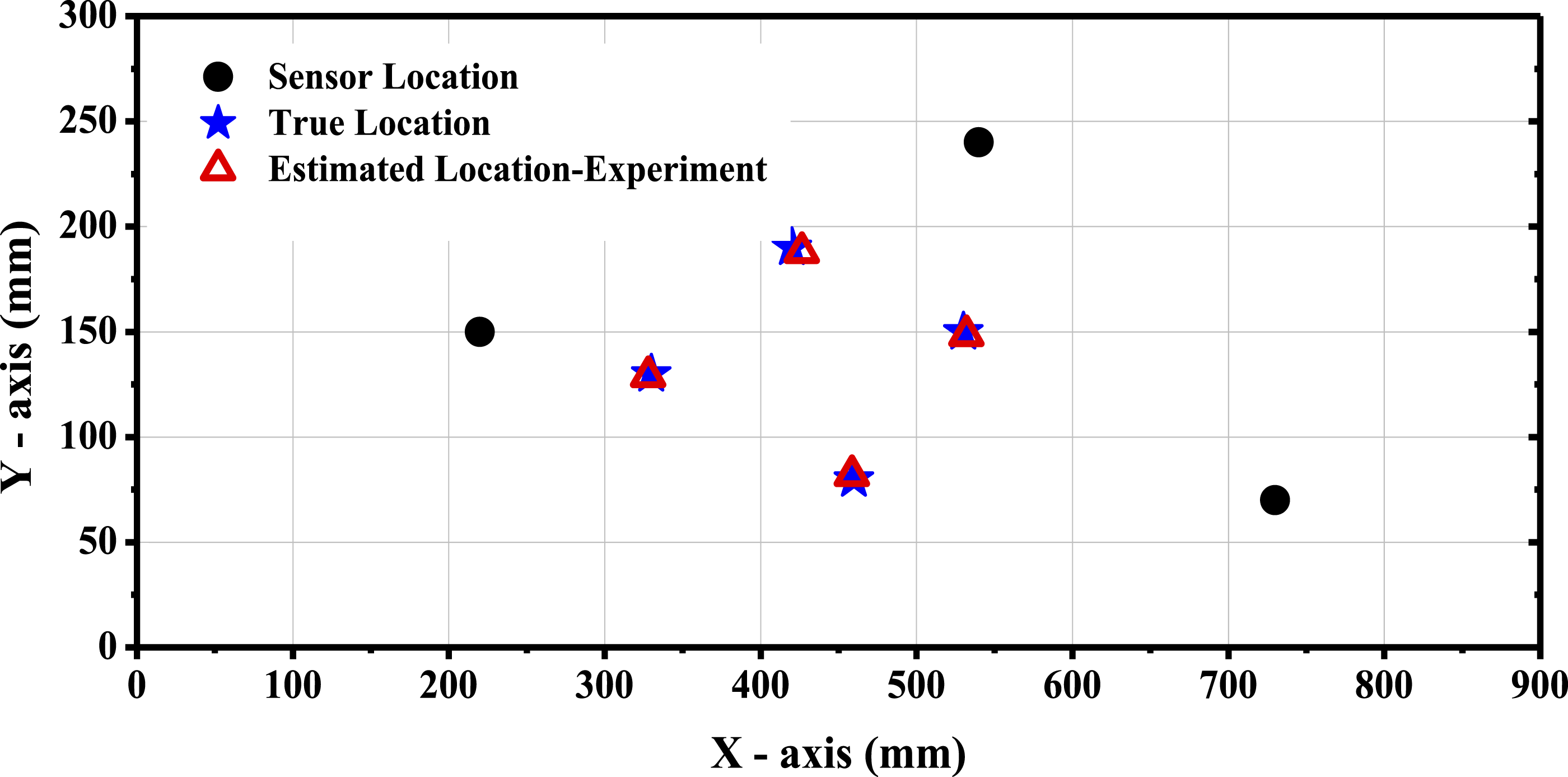
Actual and predicted impulse locations for CSIP from the top sensors.
Actual and predicted impulse locations for CSIP from the bottom sensors.
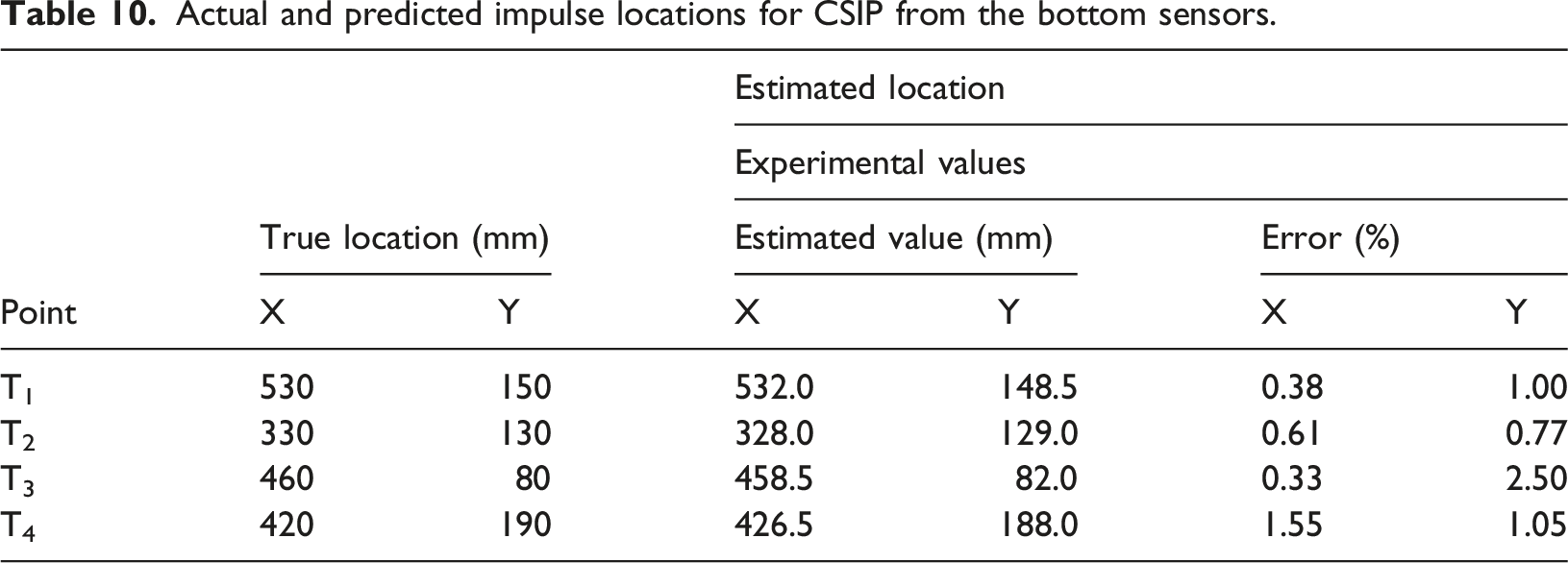
The maximum prediction error for impulse locations from both top and bottom sensors in CSIP panels remains well within 5%, as shown by the localization results in Table 9 and Table 10. The comparison of the shock locations determined from experimental results using the modified triangulation technique can be seen in Figures 12 and 13. True and estimated location of shock from the experimental results using top sensors for CSIP. True and estimated location of shock from the experimental results using bottom sensors for CSIP.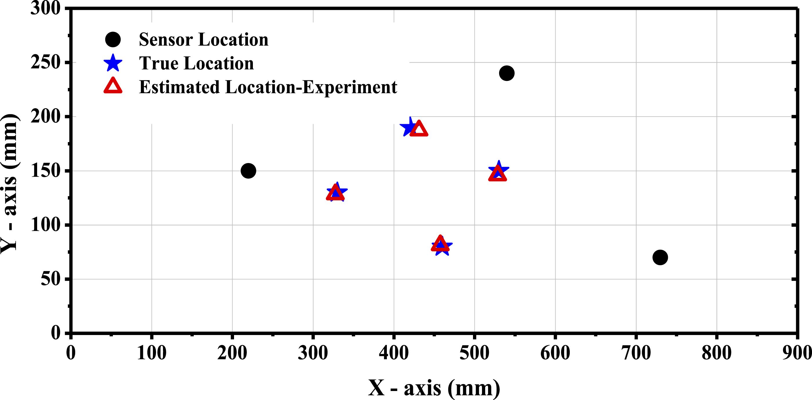
Summary and conclusions
This study introduces an innovative structural health monitoring system incorporating piezoelectric sensors embedded within smart composite structural insulated panels (CSIPs) to enhance the resilience of coastal infrastructure through continuous integrity assessment. Experimental investigations encompassing four-point bending and in-panel compression tests provided comprehensive characterization of the shock response and failure mechanisms exhibited by smart CSIPs under various loading scenarios, with all dynamic shock tests conducted using a specialized shock and impact testing simulator.
Material property characterization through quasi-static tensile testing enables precise finite element model development for future studies while facilitating detailed analysis of composite panel structural behavior. Four-point flexural tests systematically quantified the bending properties of CSIP configurations. The structural health monitoring framework successfully detected and localized shock-induced damage on CSIP top face sheets by formulating and minimizing multi-sensor objective functions based on time difference of arrival analysis. Solitary waves generated within the granular rod sensors proved highly effective for shock localization, with relative timing differences serving as robust inputs to the optimization algorithms.
The structural health monitoring framework successfully detected and localized shock-induced damage on CSIP face sheets by formulating and minimizing multi-sensor objective functions based on time difference of arrival analysis. Solitary waves generated within the granular rod sensors proved highly effective as robust and dispersion-free inputs to the triangulation algorithm, with the wave velocity parameters theoretically derived from the experimentally characterized material properties and comprehensively validated in the authors’ prior publication (Rajeev et al., 2024a). The objective functions accurately predicted peak shock wave damage locations with maximum errors below 5% across all four test locations from both top and bottom sensors, validating the efficacy of smart CSIPs for real-time health monitoring, service life extension, and catastrophic failure prevention.
It is acknowledged that the CSIP specimens tested in this study measuring 960 mm × 300 mm × 89 mm represent a reduced-scale configuration relative to full-scale coastal building panels typically ranging from 2400 mm × 1200 mm to 3600 mm × 1200 mm in plan dimensions with core thicknesses of 100–200 mm. The governing failure mode is expected to transition from shear-dominated to bending-dominated behavior as panel slenderness ratio increases with scale, with the flexural parameters of Table 5 representing conservative lower bounds for full-scale panel capacity under distributed wind loading conditions characteristic of cyclone and hurricane-prone coastal regions. While Lamb wave propagation characteristics in the aluminum face sheet are scale-invariant with respect to panel thickness, geometric spreading and material damping at larger source-to-sensor distances in full-scale panels will necessitate higher sensor network density or increased signal amplification for full-scale deployment. The granular rod sensor design is fully scalable without modification, and the TDOA localization algorithm is directly extensible to larger sensor networks through incorporation of additional sensor pairs into the objective function formulation of equations (8) and (9).
The present study acknowledges several limitations that are addressed through the following future scope, as detailed in the subsequent section: the absence of comparative mechanical testing between sensor-embedded smart CSIP and baseline conventional specimens; the non-instrumentation of the sensor network during flexural failure testing; the lack of a head-to-head experimental comparison with conventional surface-mounted Piezoelectric Wafer Active Sensors (PWAS) sensor systems; and the need for full-scale experimental validation under realistic coastal loading conditions. These limitations do not diminish the significance of the present findings but rather define a clear and structured pathway for advancing the smart CSIP technology toward practical coastal infrastructure deployment.
This comprehensive investigation validates the revolutionary capability of smart CSIPs to substantially advance structural safety and performance benchmarks. The synergistic integration of embedded piezoelectric sensor networks with sophisticated signal processing algorithms establishes a robust platform for next-generation resilient infrastructure capable of withstanding extreme environmental challenges prevalent in disaster-prone coastal regions.
Future scope
While the present study demonstrates the viability of smart CSIPs as a foundational technology for real-time shock identification and damage localization in coastal infrastructure, several research directions are identified to address the current limitations and advance the technology toward full-scale coastal infrastructure deployment.
The following future scope items are proposed to systematically address these gaps and extend the findings of the present work: • Orthotropic material characterization of the EPS core through multi-directional compression and shear testing to independently quantify directional compressive moduli, yield strengths, and shear moduli, replacing the isotropic idealization adopted in the current study, complemented by finite element modeling of the shear-dominated failure zone and face sheet–core debonding behavior. • Comparative four-point flexural testing of sensor-embedded smart CSIP specimens against conventional baseline CSIP specimens under identical ASTM C393 loading conditions, quantifying the effect of sensor integration on peak load capacity, flexural stiffness, peak deflection, failure mode, and self-weight addition through direct mass measurement providing verified structural performance data and panel design load inputs for coastal building envelope applications. • Systematic bench-top investigation of solitary wave sensitivity to Hertzian contact pre-load variation across individual sensor assemblies, enabling rigorous quantification of pre-load consistency requirements for reliable TDOA-based localization and establishing tolerance specifications for fabrication quality control. • Full-scale experimental validation of smart CSIP panels of representative coastal building envelope dimensions (2400 mm × 1200 mm to 3600 mm × 1200 mm) under realistic wind pressure and windborne debris impact loading, quantifying the shear-to-bending failure mode transition with increasing panel slenderness ratio and establishing sensor network density requirements for reliable full-scale damage localization. • Systematic head-to-head experimental comparison between the proposed embedded granular rod piezoelectric sensors and conventional surface-mounted Piezoelectric Wafer Active Sensors (PWAS) configurations on identical CSIP specimens under shock, impact, and simulated coastal environmental aging quantifying relative localization accuracy, signal-to-noise ratio, fabrication cost, installation complexity, and life-cycle maintainability to comprehensively establish the value proposition of the embedded sensor technology. • Integration of real-time acoustic emission monitoring through the embedded piezoelectric sensor network during four-point flexural failure testing, enabling TDOA-based spatial localization of discrete damage events including EPS core microcracking, 42° diagonal shear crack initiation and propagation, and face sheet–core debonding correlated against the load-deflection response to demonstrate early warning capability at sub-peak load levels and fully realize the self-diagnostic potential of smart CSIPs under quasi-static loading conditions. • Long-term durability assessment of smart CSIP panels under simulated coastal environmental conditions including salt spray exposure, thermal cycling, UV radiation, and humidity cycling, to validate the life-cycle reliability of the embedded sensor network and the structural integrity of the Aluminum face sheet–EPS core bond over the anticipated service life of coastal building envelope applications.
Footnotes
Funding
The authors disclosed receipt of the following financial support for the research, authorship, and/or publication of this article: The financial support of the Indian Space Research Organization (ISRO), Government of India under Grant No. ISRO/RES/STC/IITG/2021-22 is greatly acknowledged.
Declaration of conflicting interests
The authors declared no potential conflicts of interest with respect to the research, authorship, and/or publication of this article.