
Abstract
This article proposes a toward zero-support design method for irregular manifold manufacturing of composite materials based on layered adhesion equalization (LAE). Especially, external support in holes of irregular 3D manifold manufacturing by additive manufacturing (AM) is difficult to remove, which means toward zero-support design is indispensable to some complex curved surface components. AM largely depends on three main constraints, such as external support, layer thickness, and build time, which are mainly affected by building orientation and infill trajectory. Moreover, considering problems that variable layer thickness will bring material imbalance and residual stress heterogeneity, the layered orthogonal projection areas of the virtual printing prototype on the orthogonal planes, such as the positive plane and side plane in the 3D printing coordinate system, are introduced as LAE constraints to realize equilibrium reinforcement design (ERD) for both LAE and external support. Subsequently, using transient thermal structure coupling via finite element analysis, the transient thermal structure coupling analysis of fiber composite under multiple working conditions is further obtained. In particular, the influence mechanism of continuous fiber forming on the mechanical behavior of the topological configuration is revealed. Taking the irregular three-way manifold by concept design as an example, a specimen was fabricated using polylactic acid (PLA) with carbon fiber on the strength of fused deposition modeling. The infrared thermographs using thermal field measurement were carried out to obtain the temperature distribution during manufacture. The innovatively proposed LAE method is propitious to improve the additive manufacturability and adaptability of lightweight thin-wall structures, especially for fiber-reinforced composites. This is advantageous for utilisation in the domain of aerospace components.
Keywords
Introduction
The three-dimensional (3D) printing (3DP), also called rapid prototyping or additive manufacturing (AM), is entangled with computer-aided design, materials processing, and forming technology, in biomedical engineering, high-end manufacturing, aerospace and other multidisciplinary, including aeronautical thin-walled round tube, long endurance unmanned aerial vehicle (UAV), flapping wings UAV, and its high-aspect-ratio composite wing. The diverse technical requirements result in different processes,1–5 including commonly fused filament fabrication (FFF), laser beam melting, laser powder bed fusion, binder jetting, patched area printing, etc.
The huge emerging demands of end-use functional artifacts result in technological development. People studied the change of temperature field in the process of melt deposition 6 and analyzed the influence of temperature change on the thermal properties of materials by exploring the nonlinear changes of thermal conductivity and specific heat. The accurate control of temperature provides the basis for the reconstruction of biological tissue structure with activity. 7 Kabir et al. have studied the effect of temperature on the emission rate of microparticles in the printing process of fused deposition modeling (FDM), and pointed out that the emission rate of particles will be higher at higher working temperature. 8 Kuncius et al. improved the FDM production technology of continuous carbon fiber composites. 9 Spratt et al. analyzed the build quality and compression properties of thin-walled 304L honeycomb structures manufactured by selective laser melting (SLM). Four honeycomb wall thicknesses vary from 0.2 to 0.5 mm. 10
Composite material is an excellent type of wearable and high-temperature resistant material, widely employed in military and special civilian technology areas like high-temperature equipment protection, aircraft brake discs, etc. Mohammadizadeh and Fidan studied the effect of fiber parameters on the tensile properties of manufactured components. 11 Kubota et al. conducted tensile tests on samples with different stacking directions and studied the influence of printing path. 12 Kranz et al. presented experimental investigations on the influence of part position and orientation on the dimension accuracy and surface quality of laser additive manufacturing. 13 Saharudin et al. conducted mechanical tests on the model produced by continuous filament fabrication (CFF) and concluded that it improved the surface quality. Adding carbon fiber as filler to other materials for 3DP also has a good improvement effect. 14
Metal matrix composites (MMCs) have been widely adopted with the intention to assimilate the robust, malleable, and conductive attributes of metallic substances with the rigid, inflexible, and wear-resistant characteristics inherent in ceramics, or often, intermetallic substances, thereby achieving an ideal amalgamation or synergy of these two distinct properties. 15 MMCs are extraordinary engineering materials as they provide customizable characteristics, mutually drawing upon the desirable properties of both reinforcement and matrix constituents, hence enhancing their inherent structural and functional benefits. 16 Powder-based AM techniques, like SLM, exhibit significant versatility, accommodating a broad spectrum of powder-based materials, thus being particularly versatile to process a variety of powder materials for composite manufacturing. 17
M’Saoubi et al. discussed the material cutting process of aerospace alloys and composite materials employed in aero-engines. 18 Launay et al. designed a testing device to measure the material compressive strength of continuous fiber composite materials. 19 Kucewicz et al. experimentally compressed two different topologies of cellular structures fabricated with FDM of acrylonitrile butadiene styrene plus (ABS+) material with similar relative densities for five different deformation velocities: quasi static (1.0, 5.0, and 10.0 mm/s) and dynamic (1520.0 and 2400.0 mm/s). 20 Meshkinzar et al. amplified the acoustic field generated by a uniform thickness piezoelectric cylindrical shell by introducing a stepped thickness variation at predetermined axial locations. 21 Grauers et al. carried out mechanical compression tests of laminates, made of carbon fiber unidirectional fabric with epoxy, and studied the energy-absorbing damage mechanisms. 22 Sharma et al. carried out an analysis of the FFF structures subjected to uni-axial compressive and three-point bending load, in order to investigate the effect of strut thickness, shape, loading direction, and functional grading on compressive behavior. 23 Cipollone et al. studied a process for 3DP of an anode scaffold for lithium batteries. 24 Körber et al. fabricated 3D-printed polymer positive models for the investment casting of extremely thin-walled single crystals. 25
Focusing on the major needs of high-specific stiffness and lightweight structures in the frontier field of aerospace, the existing topology optimization design methods ignore the bottleneck of low fitness and poor manufacturability caused by different material AM processes.
In comparison with previous study 26 , the optimal build orientation of 3DP for complex curved surface components is determined by taking the support material into account. It is important to note that the optimal build orientation is not immediately apparent for most components fabricated by 3DP. Furthermore, layered orthogonal projection areas are introduced as layered adhesion equalization constraints to ensure manufacturability. In the physical experiment, the carbon fiber that pervades the specimen is clearly observed by the optical 3D surface profilometer.
Based on the previous systematic work26–29 considering the variation of material and equipment, the mathematical model of toward zero-support design is established. The toward zero-support design achieves equilibrium reinforcement design (ERD) for both layered adhesion equalization (LAE) and external support. Moreover, the physical experiment is implemented to verify the proposed LAE method.
Material Thickness Distribution of an Irregular Thin-Walled Composite
For lightweight design of thin-walled artifact structure
The greater the specific surface area, the greater the dispersion. Inspired by bionics, most structures are designed as thin-walled forms to maximize the specific strength, with multifarious ribs. The prototype thickness can be defined as the smallest distance through an object, between opposite surfaces or sides, as distinct from width or height.

It should be clarified that wall thickness values are attitude and azimuth independent, whereas the thickness proportional distribution is also size independent. Obviously, wall thickness is a relative concept that depends on scale, which is commonly considered. The distribution of material thickness can be obtained by clustering into certain
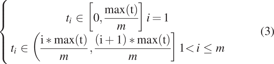
Figure 1 demonstrates different kinds of external support of the thin-walled workpiece, which is a turbine. The volume of the turbine is 8.2187 × 105 mm3. As demonstrated in Figure 1a, the volume of external support is 3.6790 × 104 mm3, which is 4.48% of the volume of the turbine. As indicated in Figure 1b, the volume of external support is 1.2419 × 105 mm3, which is 15.11% of the volume of the turbine. In Figure 1c, the volume of external support is 2.5467 × 105 mm3, which is 30.99% of the volume of the turbine. In Figure 1d, the volume of external support is 8.0252 × 105 mm3, which is 97.65% of the volume of the turbine.
Different kinds of external support of the turbine prototype where
Ultrasonic Thickness Measurement of Composite Materials
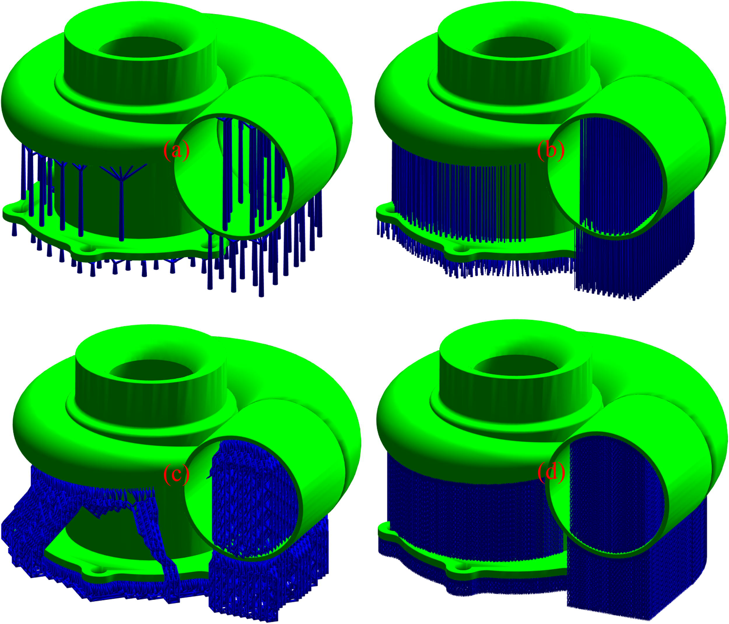
Figure 2 depicts the wall thickness distribution of a turbine. The redder the color is, the more thin-walled the structure is. From the color distribution, thin-walled structure accounts for the majority. From Figure 2c, within three classifications, the proportions of categories are 55.78%, 5.52%, and 38.70%, respectively, from thin to thick. From Figure 2d, within four classifications, the proportions of categories are 52.63%, 6.06%, 4.43%, and 36.88%, respectively, from thin to thick. From Figure 2e within five classifications, the proportions of categories are 49.80%, 7.39%, 3.08%, 3.9% and 35.73%, respectively, from thin to thick.
The wall thickness distribution of a turbine where
Ultrasonic thickness measuring sensors have contactless, nondestructive, and non-radioactive properties and can provide a real-time dynamic measurement for composite material. High temperature thickness measurement, coarse crystal thickness measurement, and some composite thickness measurements are difficult to implement.
The principle of ultrasonic thickness measurement can be described as


Due to the composite material being different from common metal and uniform nonmetal material, the common high-frequency industrial thickness probe cannot emit a sound pulse. Thus, low frequency, low residual vibration, and high-power thickness probe are required for effective penetration of composite materials. Low residual vibration is an important requirement to shorten the measurement blind area.
Using single and double crystal probes, the most ultrasonic thickness measurement system adopts the pulse-echo method, meaning the thickness of the measured workpiece is calculated by determining the time difference between the two echoes of the bottom surface.
Using a low-frequency and low-after-vibration ultrasonic thickness measuring probe, the transmission and echo signals of 130 mm thick composite materials are measured. According to oscilloscope signals, the duration of after-vibration is not more than 50 µs. The precision of this thickness measurement can reach 0.01 mm.
Fundamentals of Composite Materials for Functional Requirements
In 3D printing coordinate system (PCS), the normalized height
Resistivity and dielectric constant are important indices to evaluate the electrical properties of a material. Electrical resistivity is a physical quantity employed to express the resistance characteristics of various substances. It is not only related to materials but also related to temperature. The calculation formula of ρΩ (Ω·m) is as follows.

The thermal conductivity refers to the heat transferred through an area of 1 m2 within a certain period by a 1 m thick material with a temperature difference of 1 K on both sides of the surface under stable heat transfer conditions. The thermal conductivity kx (W/(m·K)) can be calculated by the following formula.
Dielectric constant is a physical parameter that characterizes the dielectric property or polarization property of a dielectric material. It is a property of the material itself and a parameter that measures the ability of a material to store charges. Relative permittivity is often employed to characterize the dielectric properties of materials. The relative permittivity εr is calculated by measuring the capacitance of the material thin plate, and the calculation formula is as follows.
Tensile strength σb (MPa) represents the resistance of the material to the maximum uniform plastic deformation and is the maximum stress that the material bears before breaking. Its value can be calculated by the following formula.
The dynamic pore collapse process during AM in viscous liquid can be described in the theory of cavitation. The evolution of pore radius R under the influence of external pressure and surface tension at the pore surface can be expressed in the Rayleigh–Plesset equation
30
:
Numerical Case of Manufacturability Optimization Design
3D thin-walled structure to be fabricated
The irregular three-way manifold by concept design as displayed in Figure 3 which is a complex curved surface component is employed as a calculation example to verify the foregoing theoretical method. Complex curved surface components usually refer to free-form curved surface components that contain chambers, thin-walled structures, hollow branches, and topological structures. The irregular three-way manifold is delicately designed, with thin-walled ribs. Regarding geometric and topological analysis, it has left and right symmetry. The irregular three-way manifold was designed for the cooling of extruder and filament with merely one fan. The internal channels of air flow are displayed with cut view in Figure 3b.
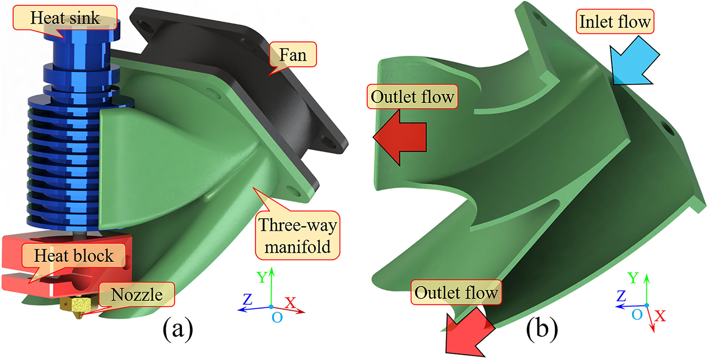
The assembly and sectional view of an irregular three-way manifold by concept design.
The slender, thin-walled functional irregular three-way manifold (Fig. 4) is employed as a calculation example to verify the foregoing theoretical method. The irregular three-way manifold is delicately designed, with thin-walled ribs. Regarding geometric and topological analysis, it has left and right symmetry.
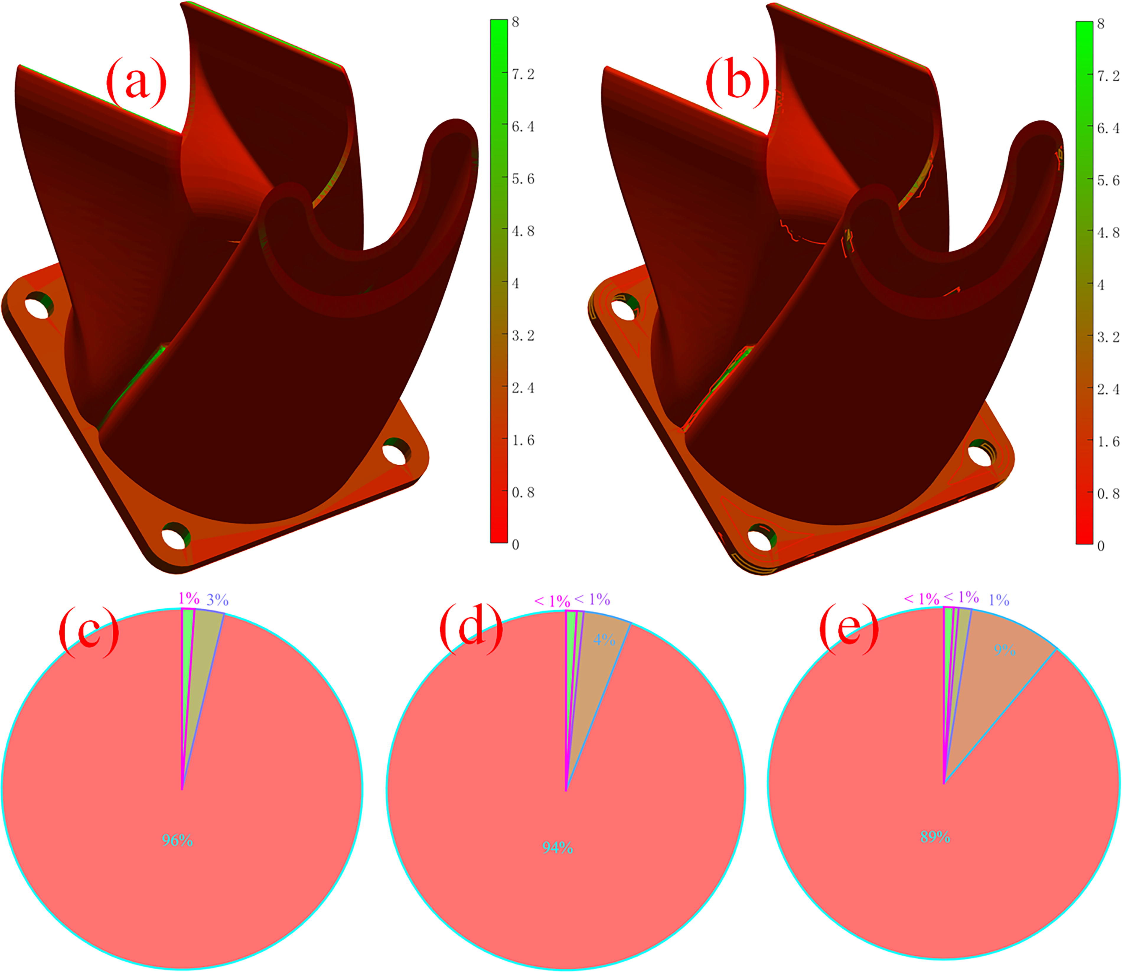
Thin-walled irregular three-way manifold with main/front view
By default, the length unit is hereinafter inclusive millimeter (mm). The overall dimension (
Using Equation (3), from Figure 4c within three classifications, the proportion of categories are 96.2361%, 2.6639% and 1.1000%, respectively, from thin to thick. From Figure 4d within four classifications, the proportions of categories are 94.0827%, 4.3316%, 0.6185% and 0.9672% orderly, from thin to thick. From Figure 4e within five classifications, the proportions of categories are 88.9012%, 8.5734%, 1.1795%, 0.4535% and 0.8923%, from thin to thick. Concerning the improved thickness, the maximum is 61.8725 mm, mean is 1.0040 mm, median value is 1.0466 mm, standard deviation is 1.3616 mm, variance is 1.8539 mm2.
Build orientation of 3DP
Figure 5 indicates build orientation under various constraints which is calculated by the manifold learning method and Powell trust region method instead of trial and error method. In machining coordinate system (MCS), the default field is (56.4396, −30.4833, 11.2981). In Figure 5a-b, the maximum is 28.0186 g at field vector (53.2651, −29.3903, 16.4680), the minimum is 4.8537 g at field vector (57.2634, −27.4090, 16.8108), the mean is 16.3393 g, the variance is 24.8029 g2, and the standard deviation is 4.9802 g. There exist 130 3D contour curves with a total of 11683 points. In Figure 5c-d, the default field is (56.4396, −30.4833, 11.2981), the maximum is 6.7984 g at field vector (59.9408, −31.5537, 14.6529), the minimum is 0.9865 g at field vector(55.3287, −33.9022, 15.7373), the mean is 3.3100 g, the variance is 1.9737 g2, the standard deviation is 1.4049 g. There exist 88 3D contour curves with a total of 11833 points.
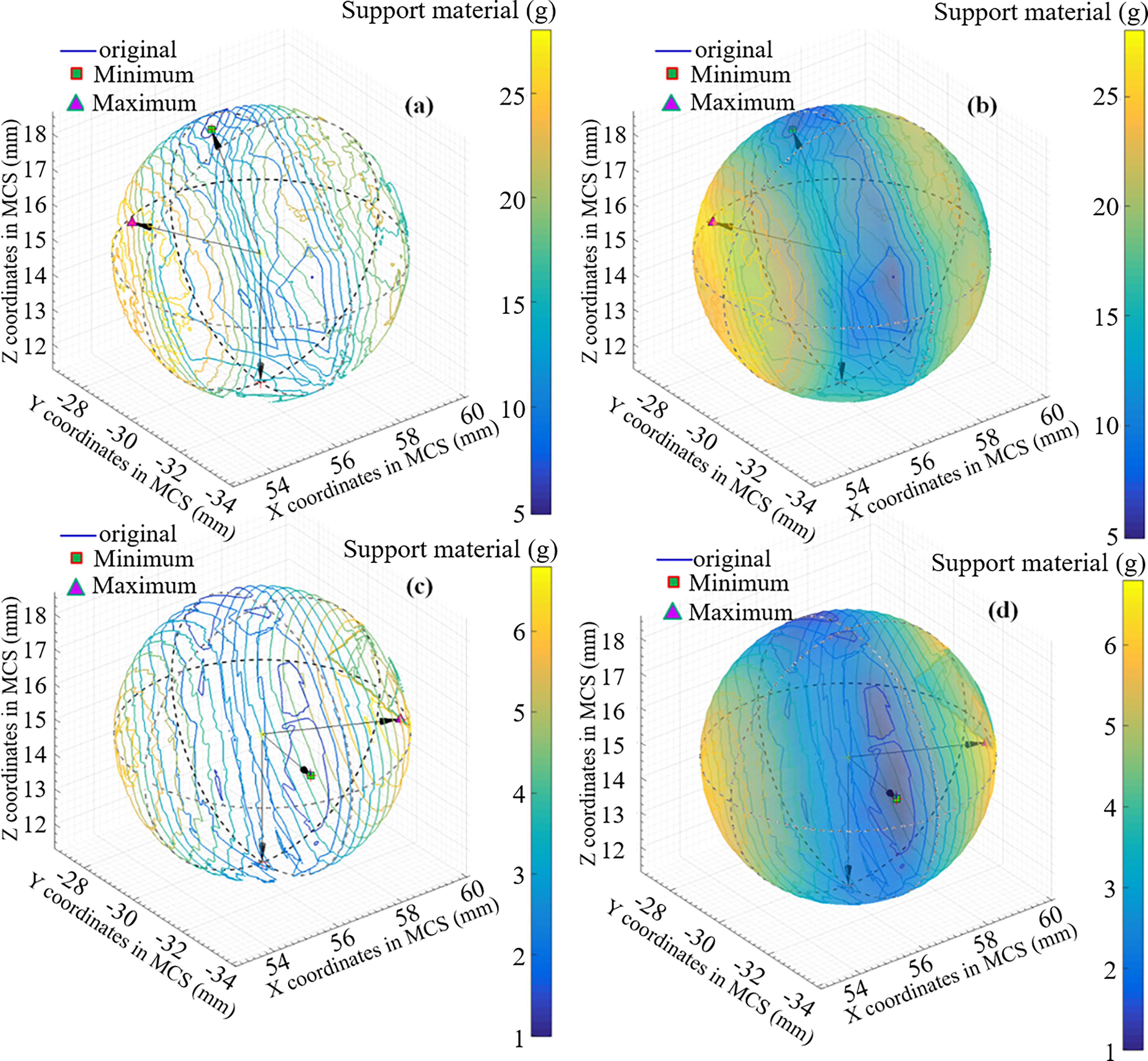
Build orientation under various constraints where
Different kinds of external supports are illustrated in Figure 6, the surface area of wired wall support is 83.17 cm2 as revealed in Figure 6a; the surface area of wired wall support is 113.19 cm2 in Figure 6b; the surface area of wired wall support is 85.29 cm2 in Figure 6c; the surface area of wired wall support is 156.61 cm2 in Figure 6d. There is no external support in the hole of the prototype. Due to stability and structural integrity, a solid type of external support is employed.
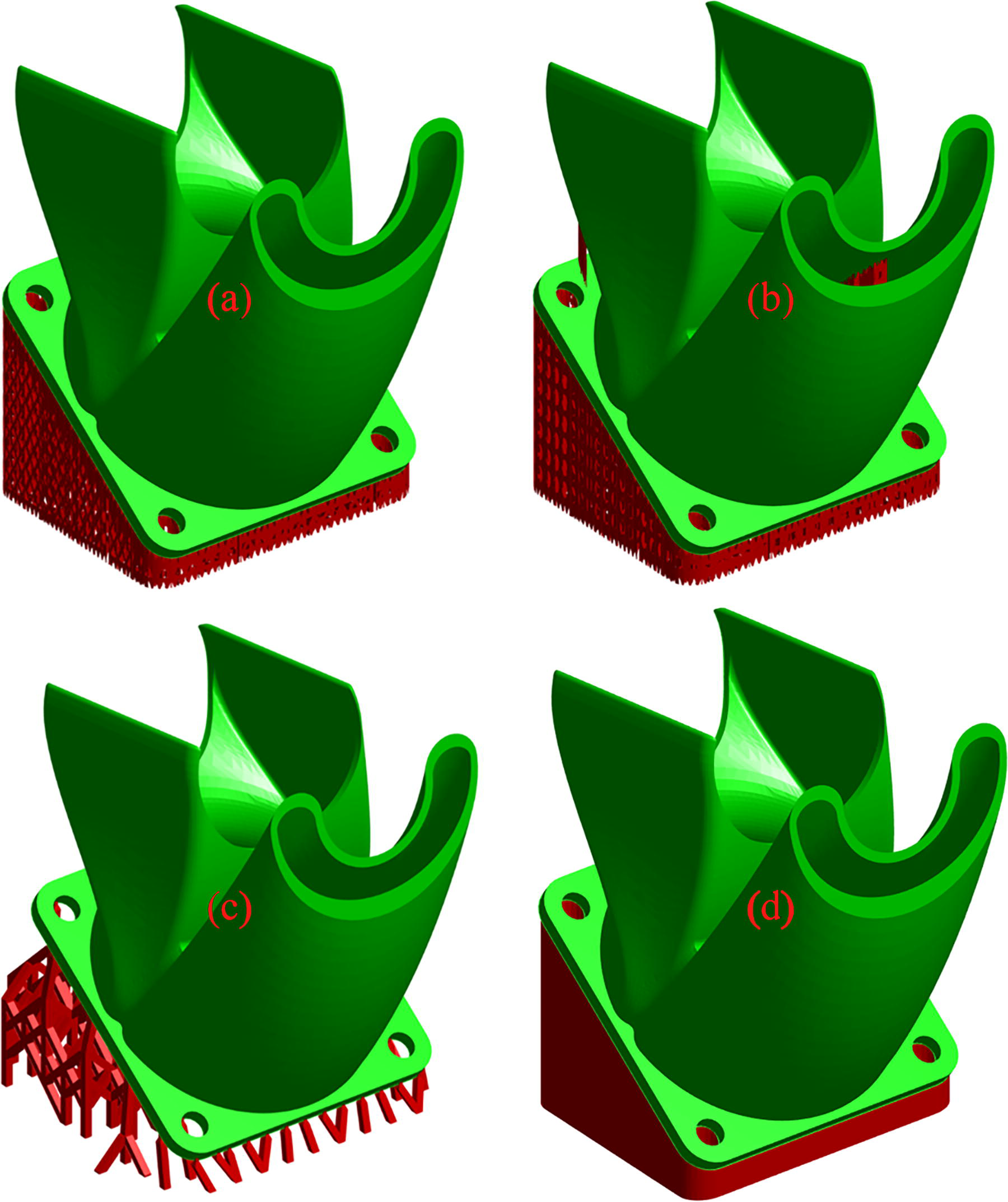
Different kinds of external support of the irregular three-way manifold where
The manufacturability at each stratification can be visualized per layer by utilizing virtual print technology in Figure 7.

Manufacturability at each stratification where
The Figure 8 illustrates the percentage of layered surface area and volume. From Figure 8a, in terms of volume of original manifold, maximum is 4.7240% at 42%, standard deviation is 0.0105, variance is 0.0001. In terms of surface area of original manifold, maximum is 4.0397% at 44%, standard deviation is 0.0099, variance is 0.0001. From Figure 8b, in terms of volume of manifold with external support, maximum is 3.3200% at 46%, standard deviation is 0.0096, variance is 0.0001. In terms of surface area of manifold with external support manifold, maximum is 3.0884% at 46%, standard deviation is 0.0082, variance is 0.0001.
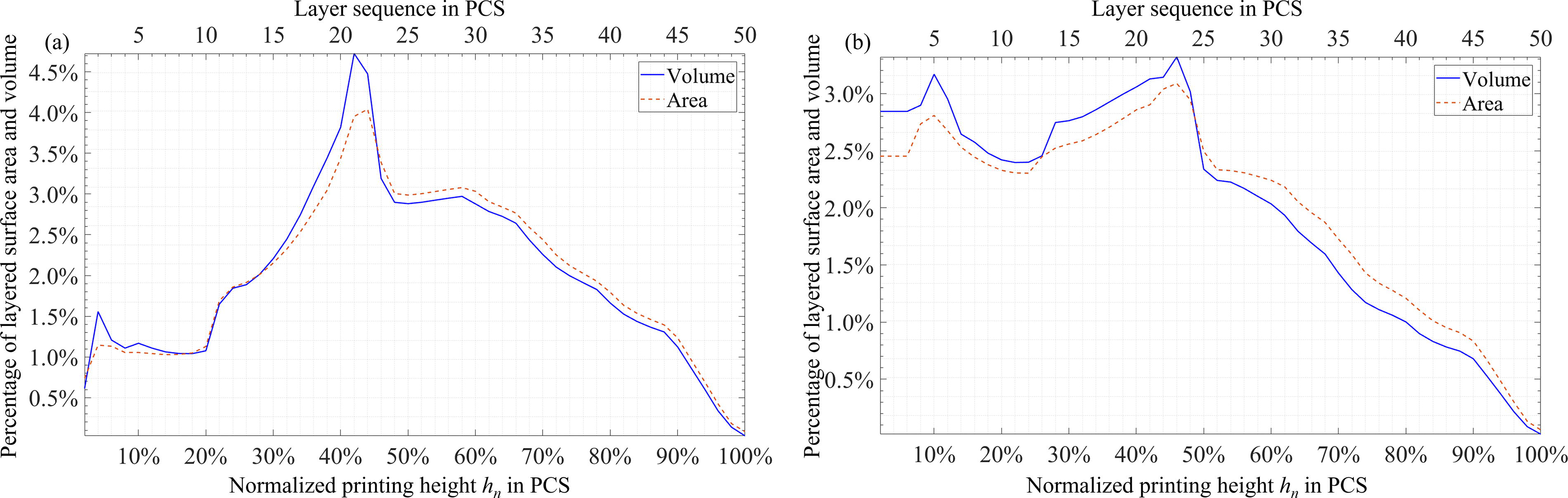
Percentage of layered area and volume
Layered orthogonal projection areas using digital twins
Based on Euler manifold theory, for any prototype in space, if the original coordinates are continuous, the parallel orthographic projection to any plane is also continuous. Especially, considering problems that variable layer thickness will bring material imbalance and residual stress heterogeneity, the layered orthogonal projection areas of the virtual printing prototype on the orthogonal planes, such as positive plane and side plane in the PCS, are introduced as layered adhesion equalization (LAE) constraints to realize equilibrium reinforcement design (ERD) for both LAE and external support.
Figure 9 depicts the layered orthogonal projection areas of various slicing thicknesses. In Figure 9a, before optimization, using thickness with 40 layers, about the area in vertical plane, maximum value is 57.5797 mm2 at 12.8205%, summation is 1875.6806 mm2, average value is 48.0944 mm2, standard deviation is 12.8594 mm2, and meanwhile, variance is 165.3634 mm4. About the area in width plane, maximum value is 63.2827 mm2 at 43.5897%, summation is 1663.9272 mm2, mean is 42.6648, standard deviation is 20.4632 mm2, variance is 418.7428 mm4. About the sum of prior areas, maximum value is 119.3708 mm2 at 43.5897%, summation is 3539.6078 mm2, mean is 90.7592 mm2, standard deviation is 26.2425 mm2, variance is 688.6665 mm4.
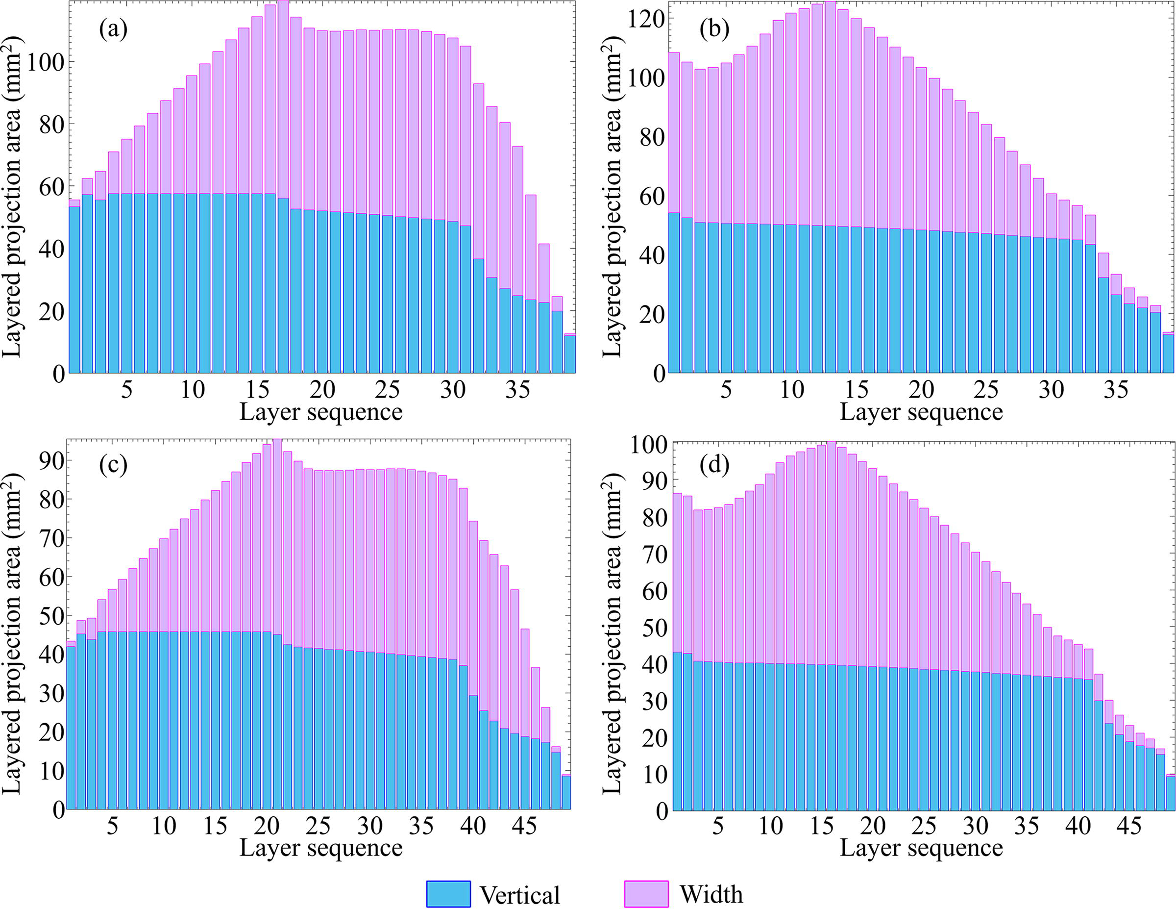
Layered orthogonal projection areas of various slicing thickness where (a), (c) are before optimization and (b), (d) are after optimization. Vertical refers to the layered orthogonal projection area in vertical plane. Width refers to the layered orthogonal projection area in width plane.
In Figure 9b, after optimization, using thickness with 40 layers, about the area in vertical plane, maximum is 54.1803 mm2 at 2.5641%, summation is 1743.4440 mm2, mean is 44.7037 mm2, standard deviation is 9.9288 mm2, variance is 98.5815 mm4. About the area in width plane, maximum is 75.9019 mm2 at 33.3333%, summation is 1666.1659 mm2, mean is 42.7222 mm2, standard deviation is 24.8400 mm2, variance is 617.0274 mm4. About the sum of prior areas, maximum is 125.6269 mm2 at 33.3333%, summation is 3409.6100 mm2, mean is 87.4259 mm2, standard deviation is 33.0332 mm2, variance is 1091.1917 mm4.
In Figure 9c, before optimization, using thickness with 50 layers, about the area in vertical plane, maximum is 45.8287 mm2 at 10.2041%, summation is 1875.6806 mm2, mean is 38.2792 mm2, standard deviation is 10.2171 mm2, variance is 104.3882 mm4. About the area in width plane, maximum is 50.2854 mm2 at 42.8571%, summation is 1663.9272 mm2, mean is 33.9577 mm2, standard deviation is 16.2589 mm2, variance is 264.3514 mm4. About the sum of prior areas, maximum is 95.4078 mm2 at 42.8571%, summation is 3539.6078 mm2, mean is 72.2369 mm2, standard deviation is 20.8554 mm2, variance is 434.9493 mm4.
In Figure 9d, after optimization, using thickness with 50 layers, about the area in vertical plane, maximum is 43.1231 mm2 at 2.0408%, summation is 1743.4440 mm2, mean is 35.5805 mm2, standard deviation is 7.8879 mm2, variance is 62.2191 mm4. About the area in width plane, maximum is 60.6111 mm2 at 32.6531%, summation is 1666.1659 mm2, mean is 34.0034 mm2, standard deviation is 19.7220 mm2, variance is 388.9578 mm4. About the sum of prior areas, maximum is 100.2057 mm2 at 32.6531%, summation is 3409.6100 mm2, mean is 69.5839 mm2, standard deviation is 26.2285 mm2, variance is 687.9322 mm4.
Transient Thermal Structure Coupling Analysis of Composite
The finite element analysis (FEA) is conducted based on transient thermal structure coupling theories, using quasi-linear solution with 8-node three-dimensional thermal solid element. And the structure analysis is implemented via mesh domain decomposition method.
The prototype is simulated with composite PLA as the material. The density of the adopted material is 1.27 g/cm3, the coefficient of thermal expansion is 2.25 × 10⁻⁵ °C-1, the printing temperature is 220 °C, and the isotropic thermal conductivity is 0.18 W·m−1·°C−1. When implementing simulation, the preheat temperature is set to 55 °C, the room temperature is 25 °C, the scan speed is 600 mm/s, the hatch spacing is 0.13 mm, and the deposition thickness is 0.2 mm.
The simulation conditions of FEA are depicted in Figure 10. Figure 10a illustrates the temperature distribution after manufacturing, with an average temperature of about 99.9831 °C. Figure 10b displays the equivalent elastic strain of the fabricated fan duct with a maximum of 0.0074. Figure 10c demonstrates the total fabricating displacement with the average deformation of 0.0592 mm. Figure 10d–f correspondingly displays the directional displacement along the
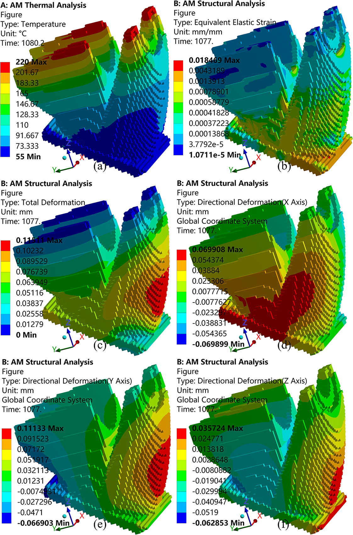
Finite element analysis of composite materials.
FEA Outcomes with Fiber Composite Materials
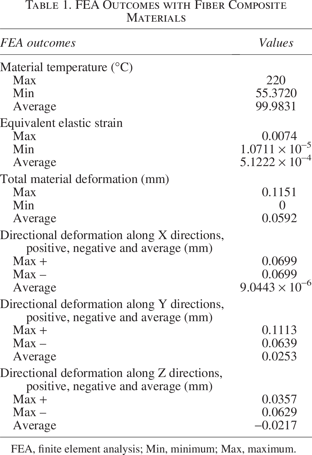
FEA, finite element analysis; Min, minimum; Max, maximum.
Physical Experiment
The FDM equipment is an extrusion-based 3D printer at ambient temperature 25 °C with 55% RH (relative humidity). The layer thickness can be varied among [0.10 mm, 0.35 mm]. The rated power is 350 W, powered by AC (alternating current) 220 V to ensure the high temperature up to 220 °C of composite 3DP.
The adhesion manufacturing process was observed by an infrared thermal imaging camera on the strength of Stefan–Boltzmann law on black-body radiation captured as Figure 11. The measurable temperature range is [−20 °C, 350 °C]. The temperature accuracy is the maximum of ±2% reading and ±2 °C. The field of view is 23° × 17°. The detector type is an uncooled microbolometer with 60 × 120 focal plane array. The scan trajectories could be observed in Figure 11.
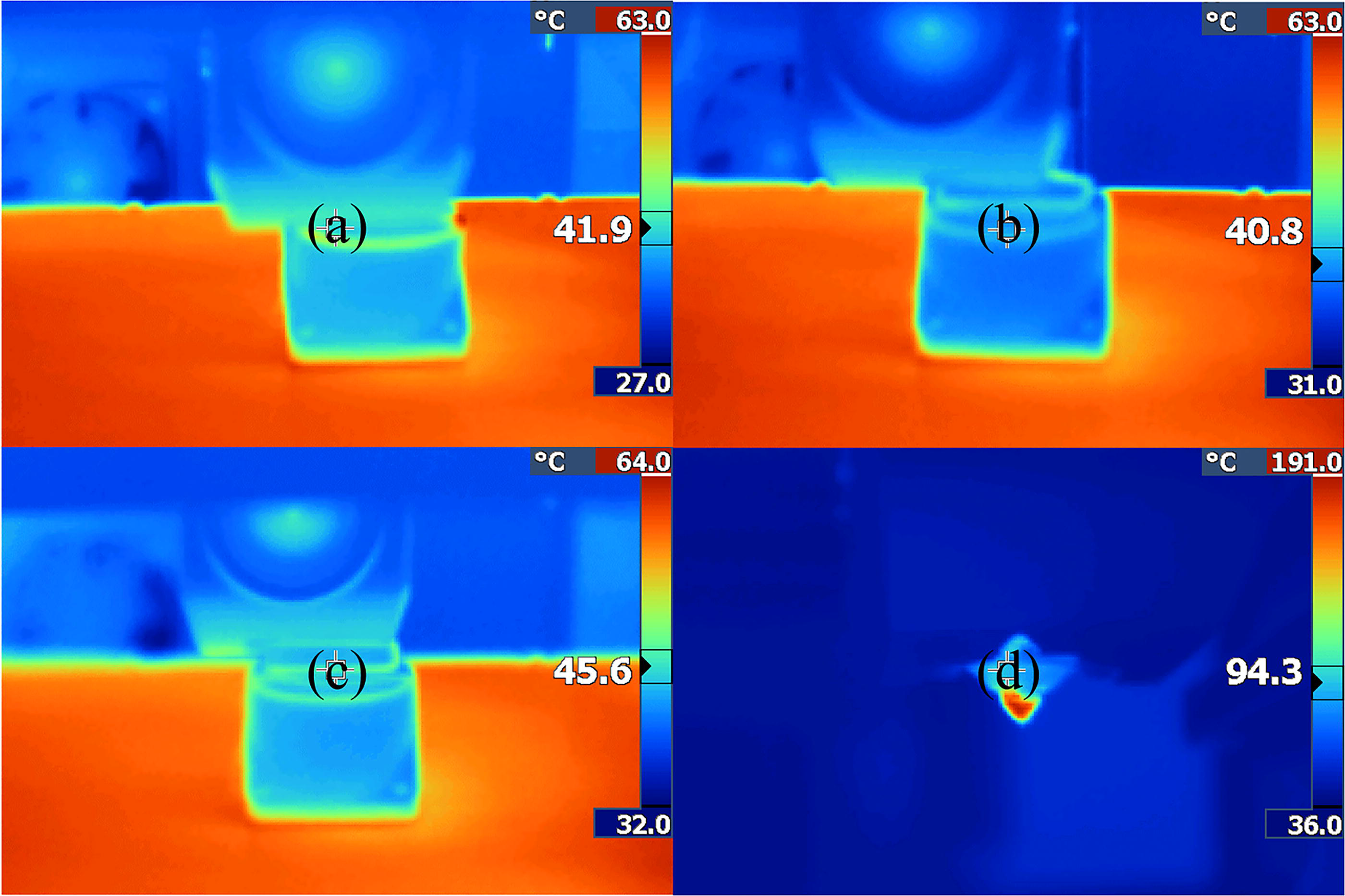
Infrared imagery of the adhesion manufacturing process where
Figure 12 displays the physically fabricated lightweight specimen using the proposed method with composite material. The composite material is polylactic acid (PLA) with carbon fiber. The carbon fiber increases the bending strength and toughness of the specimen. Meanwhile, the carbon fiber improves the heat resistance, abrasive resistance, and corrosion resistance.
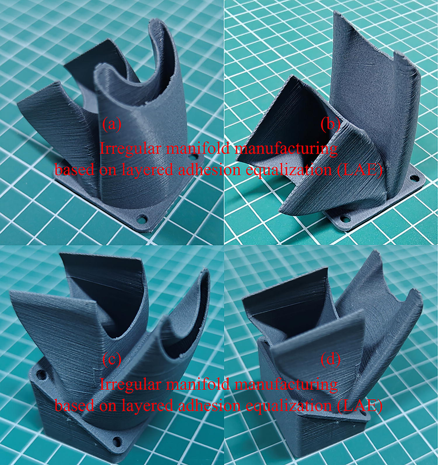
Physically fabricated lightweight specimens using the proposed LAE method, where
Figure 13 displays the layered adhesion surface topography of the fabricated specimen, where the magnification is 20×. As the surface topography demonstrated, the carbon fiber pervades the specimen.
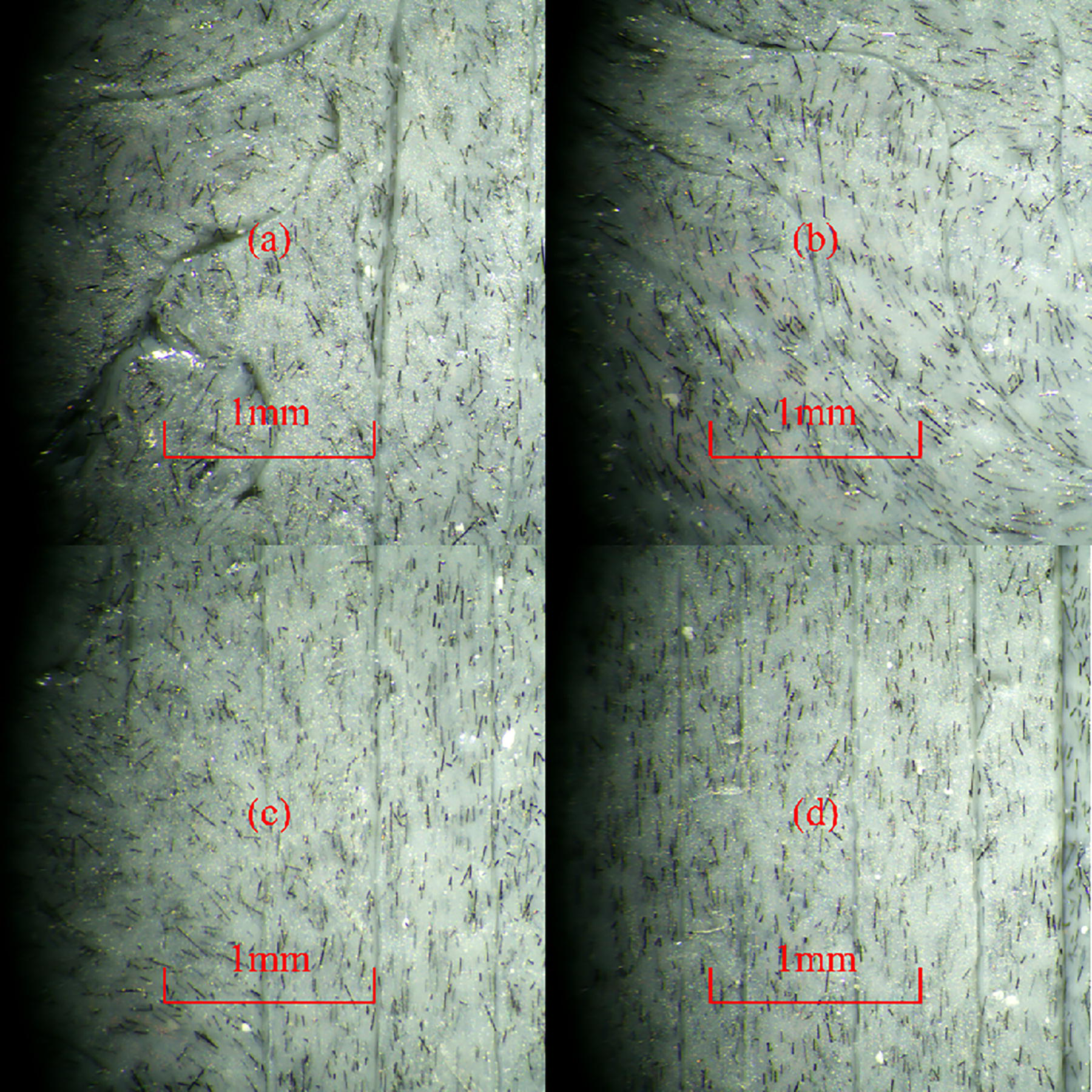
Adhesion surface topography of the fabricated specimen made of fiber composite materials.
Conclusions
Toward zero-support design for irregular manifold manufacturing of composite materials based on LAE.
The toward zero-support design prototype is built at different layers, by considering build orientation, external support, adaptive thickness, as well as layered orthogonal projection areas. Especially, considering problems that variable layer thickness will bring material imbalance and residual stress heterogeneity, the layered orthogonal projection areas of the virtual printing prototype on the orthogonal planes, such as positive plane and side plane in the PCS, are introduced as LAE constraints. The LAE method can thus improve the overall manufacturability by virtue of toward zero-support design. Overall, the toward zero-support design achieves ERD for both LAE and external support.
Using transient thermal structure coupling to obtain temperature, deformation, and force line response of composite materials.
The temperature and deformation of both noncomposite and composite materials during 3DP are compared to confirm the manufacturability using FEA of transient thermal structure coupling. Transient thermal structure coupling analysis of composite is further obtained. Subsequently, the influence mechanism of continuous fiber forming on the mechanical behavior of topological configuration is revealed, which lays a foundation for the lightweight design of continuous fiber reinforced structures with AM constraints.
A specimen was fabricated using PLA with carbon fiber by FDM.
Taking the irregular three-way manifold which is a complex curved surface component as an example, the infrared thermographs using thermal field measurement are carried out to obtain temperature distribution. Subsequently, the surface topography of the fabricated specimen was observed by a microscope with a magnification of 20×. As the topography demonstrated, the carbon fiber covered the surface and pervaded the specimen to increase the bending strength, toughness, heat resistance, abrasive resistance, and corrosion resistance. The proposed LAE method contributes to improving the additive manufacturability and adaptability of lightweight thin-wall structures, especially for fiber-reinforced composites.
In the future, the proposed method can be utilized in automobile, electromechanical, aerospace, biomedical, and other customized fields, especially heavy load-bearing and special bioelectrical requirements. In particular, the proposed LAE method is propitious to fabricate complex irregular manifolds of aircraft, automobiles, and so on. And it is anticipated that the proposed ERD methodology will facilitate advancements in support-free 3D printing as well as microgravity support balanced reinforcement design for outer space manufacturing.
Authors’ Contributions
M.G. carried out the analytic mathematical programming and theoretical computation in the continuous domain. L.W. conducted the finite element analysis. J.X. finalized the article. S.Z. guided the team’s research as a Principal Investigator. J.T. made constructive suggestions to the work as a Chief Scientist.
Footnotes
Author Disclosure Statement
No competing financial interests exist.
Funding Information
The work is funded by National Key Research and Development Project of China (Grant No. 2022YFB3303303); Key Open Fund of State Key Laboratory of Materials Processing and Die & Mould technology of China (Grant No. P2024-001).