
Abstract
Hybrid continuous fiber-reinforced composite structures are widely used in aerospace, but they show poor printing quality and unstable performance. Thus, the additive manufacturing process and mechanical behaviors of carbon–Kevlar intralayer hybrid continuous fiber composite corrugated sandwich structures are experimentally investigated. All samples are fabricated using an in-situ impregnation method based on the one-stroke path planning. The inherent intralayer fiber hybridization mechanism and the effects of 3D printing parameters (layer thickness, temperature, and speed) on printing quality and mechanical performance are focused. The protection mechanism based on intralayer hybridization, meso-structural characteristics, and failure modes is analyzed. Results reveal that Kevlar fibers protect carbon fibers during printing, reducing nozzle friction and preventing brittle fractures. However, parameter mismatches (e.g., extrusion amount and temperature) between carbon and Kevlar fibers lead to surface defects and uneven impregnation. Quasi-static crushing tests demonstrate that hybrid samples exhibit superior energy absorption and load stability compared to single-fiber samples, attributed to the synergy effect of high-strength carbon and tough Kevlar fibers. Optimal printing parameters enhance impregnation and interlayer bonding, minimizing the defects. This study provides valuable exploration for the 3D-printing and mechanics of intralayer hybrid fiber composite structures.
Introduction
Additive manufacturing (3D printing) is an advanced technology that constructs three-dimensional objects through layer-by-layer material deposition,1,2 gaining significant attention for its immense potential in rapid prototyping of complex components.3–5 In recent years, this technology has also made rapid progress in the field of continuous fiber-reinforced composites,6–10 enabling the production of intricate composite structures.11–14 While fused deposition modeling remains the most widely used technique in continuous fiber additive manufacturing,12,15,16 inherent limitations of its process characteristics often result in 3D-printed composites exhibiting multiple defects, low surface precision, and weak mechanical properties. These issues hinder their ability to meet the manufacturing and performance requirements of equipment across various fields, thereby restricting the application scope of this process.17–19
To improve the mechanical properties of 3D printing, research on continuous fiber 3D printing has become the focus of the scientific community.20–26 Continuous fibers not only endow the printed composites with a stronger mechanical response but also enable them to have excellent energy absorption capacity. 27 However, this energy absorption capacity is closely related to various process parameters. Therefore, optimizing these parameters is a key link in the manufacturing process. Chen et al. 22 investigated the mechanical properties and molding quality of continuous glass fiber-reinforced composites at different nozzle temperatures. As the temperature rises, the mechanical properties improve. However, when the temperature exceeds 210°C, it is difficult to ensure the dimensional stability of product edges. Hou et al. 13 studied the influence of layer thickness on the mechanical properties of continuous Kevlar fiber-reinforced PLA. It was found that as the layer thickness decreases, the interlayer adhesion quality and mechanical properties of the sample are enhanced. Zhang et al. 28 studied the influence of printing speed on the mechanical properties and surface quality of carbon fiber-reinforced composites. It was found that as the printing speed increases, the flexural modulus of the sample shows a downward trend, and the surface quality of the sample is rougher.
Despite significant breakthroughs in the research on process parameters of continuous fiber 3D printed composites, their single mechanical properties are still affected by fiber types.17,29–33 To this end, hybrid fiber composites can achieve synergistic optimization of key properties such as strength, toughness, and impact resistance through the synergistic effect of multiple fibers, while reducing dependence on single fiber resources. For example, hybridization of carbon fiber and Kevlar fiber can not only improve overall strength of composite but also improve the fracture toughness of carbon fiber. Hence, more and more scholars have been paying close attention to the design and hybrid effects of hybrid fiber composites. Ding et al. 29 implemented interlayer hybridization of carbon fiber and glass fiber by laying different fibers on different layers. After research, it was found that under the same carbon/glass fiber content ratio, different carbon/glass fiber layer arrangement patterns have a quite significant impact on the mechanical properties of this material. Among them, the difference in tensile strength can be as high as 20%, and the difference in impact strength can reach 35%. Zia et al. 31 carried out hybridization operations on hybrid carbon/Kevlar fibers using the in-situ impregnation method and tested their tensile strength, three-point bending strength, and drop weight impact strength. The results show that hybrid composites perform better than non-hybrid composites in these aspects. Ding et al. 32 also mixed and laid carbon fiber and glass fiber in the same layer. It was found that when the proportion of glass fiber gradually increases, the energy absorption of the sample will be greatly improved. Compared to pure carbon fiber parts, the sample with a hybrid ratio of 0.75 has its tensile strength increased by about 10%, and the impact strength is increased by 2.3 times, fully demonstrating a good toughening effect. However, there are still certain limitations to the interlayer fiber hybridization of composites, such as the low dispersion of different fiber hybridization, which leads to local weakness in each layer. Conversely, the intralayer fiber hybridization can improve the brittleness characteristics of carbon fibers better and more uniformly with high-toughness fibers. In addition, in the manufacturing of intralayer hybrid fiber composites, carbon fibers and Kevlar fibers are arranged in the same path using a “one stroke” path planning to avoid fiber cutting and ensure continuity, which is different from interlayer hybridization methods.
Currently, there is relatively little research on the process parameters of hybrid fibers. Since the optimal process parameters for carbon fiber and Kevlar fiber are not the same, this will lead to difficulties in optimizing their process parameters. The 3D printing mechanism of hybrid fibers is extremely complex, with problems such as uneven extrusion of the matrix, uncertain fiber arrangement positions, and low impregnation rates. Therefore, it is very necessary to study the additive manufacturing methods and the hybrid mechanism in terms of mechanical properties for multiple fiber-reinforced composites.
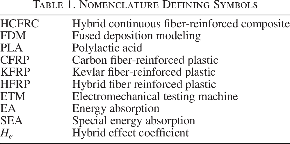
This study focuses the inherent hybridization mechanism on additive manufacturing and mechanical behaviors of intralayer hybrid continuous carbon fiber-reinforced plastic (CFRP)/Kevlar fiber-reinforced plastic (KFRP) corrugated sandwich structures. Based on 3D-printing technology, CFRP, KFRP, and CFRP/KFRP corrugated sandwich structures are fabricated (All defining symbols are shown in Table 1). The effects of 3D-printing process parameters on printing quality and properties are investigated. Through characterization techniques, the printing defects and surface quality of different corrugated sandwich structures are analyzed to unveil the hybrid effects on additive manufacturing. Subsequently, the effects of hybrid mechanisms on failure modes and mechanical properties are studied. Finally, some new phenomena and mechanisms were discovered, which can provide valuable exploration for the 3D-printing of intralayer hybrid fiber composites.
Nomenclature Defining Symbols
Experiment and Methods
3D-printer platform and materials
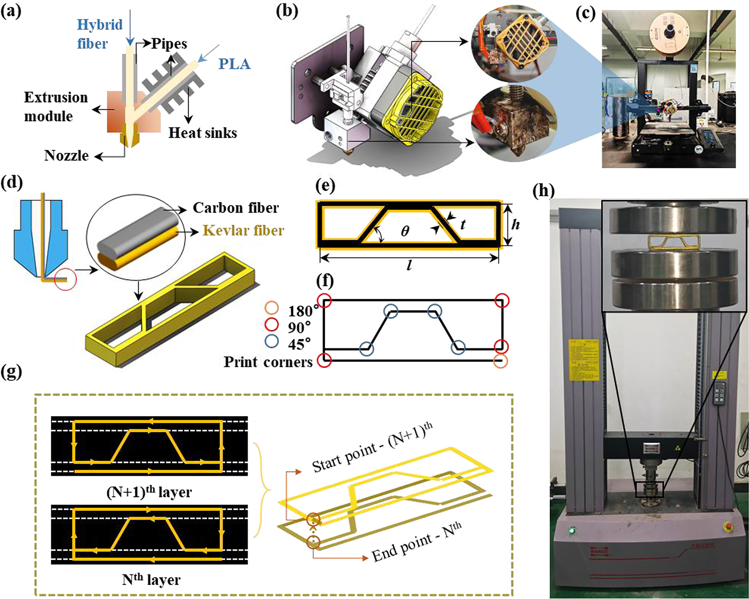
The continuous fiber composite 3D printer used in this study was customized by retrofitting an ENFER-3v2NEO 3D printer with optimized nozzle and extrusion systems. The in-situ impregnation method is used to manufacture the hybrid intralayer continuous fiber-reinforced composite (CFRC), as shown in Figure 1(a). This process is already one of the widely used methods in the field of CFRC additive manufacturing.34–36 Compared with the pre-impregnation double-nozzle process, the in-situ impregnation method synchronously extrudes two fibers through a single nozzle. This avoids interlayer alignment errors and improves manufacturing efficiency. Its feature of no pre-impregnation reduces the cost and is more suitable for integrated molding of complex structures. Therefore, this method is used to fabricate single-fiber and hybrid-fiber composite corrugated sandwich structures. Figure 1(b)−(c) shows the 3D printing equipment.
In terms of materials, the two types of continuous fibers adopted are carbon fibers sourced from Toho HTA40 E15 1K in Japan (1K, 1.78 g/cm3) and high-performance Kevlar fibers (840d, 1.440 g/cm3) produced by DuPont in the United States. The matrix used is PLA/1.75 mm produced by Shenzhen Creality 3D Technology Co., Ltd.
Design of structure and 3D-printing path
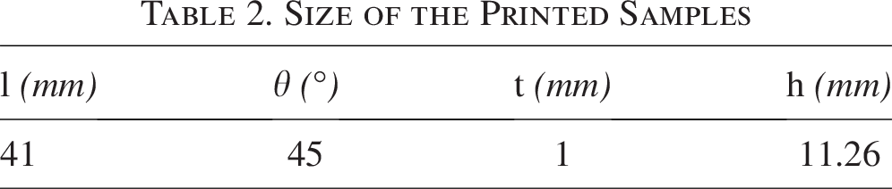
Figure 1(d) presents the three-dimensional model of the HFRP corrugated sandwich structure. Figure 1(e)−(f) shows the size marking and main corners of the HFRP corrugated sandwich structure. The specific dimensions of the structure are shown in Table 2. This printer does not introduce a fiber-cutting mechanism in the entire process of continuous fiber 3D printing. Thus, the traveling path of the hybrid continuous fibers must be able to achieve a “one-stroke drawing.”31,37 The continuous fiber path was planned, as shown in Figure 1(g). This path is divided into odd layers (Nth) and even layers ([N + 1]th), and the paths of different layers are different. Upon the termination of each layer’s printing trajectory, the nozzle swiftly elevates and transitions to the initial location for the ensuing layer. By using this specific path, no path jumping or crossing occurs during the printing process, thereby ensuring that the fiber printing can be completed in one go.
Size of the Printed Samples
Experiment procedures and setup
Process parameters
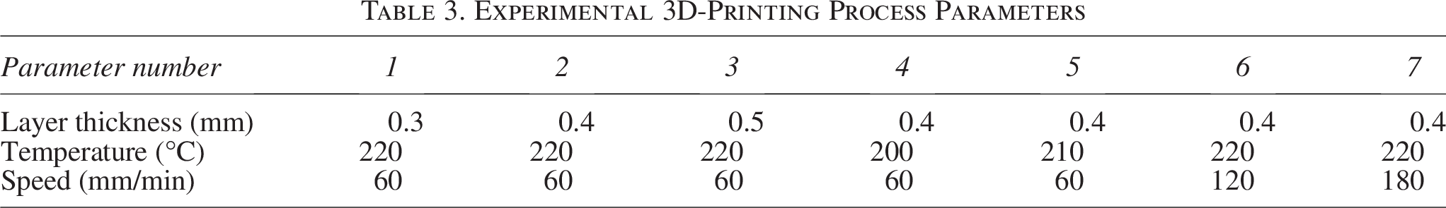
In the present experiment, three common parameters in continuous fiber 3D printing were selected, namely layer thickness, temperature and printing speed. Subsequently, the samples were numbered. As for the details of the process parameters for different numbers in the experiment, please refer to Table 3. The comparison of process parameters used in this experiment was based on standard no. 2, as individual process parameters have been analyzed, and the effects of temperature and speed on manufacturing success rate and printing efficiency have been considered in previous experiments. The nozzle size was selected to be 1.0 mm in diameter, and the length of the immersion chamber was 12 mm. The back pressure adjustment was completed by a 3D printing extruder, based on the mechanical screw-gear coordinated adjustment, the back pressure is about 0.3 MPa, which was selected according to the pure PLA matrix 3D printing.
Experimental 3D-Printing Process Parameters
Characterization test
The HRX-01/RX-100 ultra-depth-of-field microscope was utilized to conduct a detailed analysis of the sample surfaces, examining the interlayer printing effects and identifying existing defects across various process parameters. At the same time, the surface roughness of the samples was quantified using a white light interferometer to ascertain the distinctions among different fibers.
Quasi-static crushing test
To evaluate the mechanical properties of the samples, an electromechanical testing machine (ETM) series electronic universal testing machine (Shenzhen Wance Testing Equipment Co., Ltd.) was adopted to conduct quasi-static crushing tests, as shown in Figure 1(h). The experimental crushing displacement was set to 7 mm. The loading speed was determined to be 1 mm/min, and the corresponding force-displacement curves were generated. Subsequently, their performances were evaluated based on the total energy absorption (EA), specific energy absorption (SEA). During the crushing process of the corrugated structure, the total dissipated energy EA is represented by the area under the load/displacement curve. These indicators are used to determine the optimal printing process parameters for different fibers.
EA is the total area under the load–displacement diagram.
SEA is a critical assessment index of performance for energy-absorbing structures and is the energy absorbed per unit mass of crushed structure expressed in J/g.
Results and Analysis on Additive Manufacturing
3D-printing samples
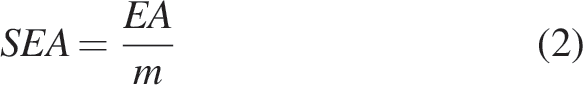
Due to the macroscopical similarity of samples printed with different parameters. Figure 2(a1–a4) shows HFRP with process parameter no. 1, HFRP with process parameter no. 2, CFRP with process parameter no. 2, and KFRP with process parameter no. 2, respectively. Figure 2(b) displays the top views of different fiber samples. As shown in Figure 2(c1–c3), the surface of HFRP has significantly more protrusions than those of KFRP and CFRP samples. This phenomenon is caused by uneven matrix extrusion, and it also appears in HFRP with other process parameters. At the same time, the surface roughness of the fiber was characterized by a white light interferometer, the surface roughness of KFRP and CFRP are 55 µm and 101 µm, respectively, as shown in Figure 2(c4–c5). For the HFRP, higher surface roughness (126 µm) is identified from Figure 2(c5), which verifies the influence of fiber hybridization on the 3D-printing surface quality, as compared to single-fiber composite.
The printing sample of
Figure 2(d1–d3) shows the failed 3D printed composite corrugated sandwich structure samples. The reason for the printing failure of CFRP is fiber breakage, while the reason for the printing failure of HFRP is the lack of matrix, which makes the fiber path unable to be fixed. This phenomenon is due to the short immersion time during high-speed printing, and the insufficient immersion results in the formation of pores. The adhesion of the matrix to the fibers is weak, and the fibers carrying the molten matrix are unstable when extruded, resulting in insufficient fixation of the matrix.
CFRP with process parameter nos. 2 and 6, fail to be printed. This is because carbon fiber is prone to brittle fracture, especially when passing through the nozzle. It is highly likely to be cut and broken due to excessive friction. These fractured fiber segments often accumulate inside the nozzle and gradually become thinner during the printing process, eventually breaking completely, the printing process of the fiber extruded sample could not continue, and the wear and fracture process of the CFRP is shown in Figure 2(e1–e2).
HFRP with process parameter no. 7 fails to be printed. The reason for this result is that under the condition of a relatively large diameter of the hybrid fiber and excessive printing speed, the matrix has an unstable phenomenon in the actual extrusion process. This situation leads to a decrease in the extrusion amount of the matrix on a certain path, so that the path cannot be successfully fixed and the printing fails. At the same time, under the condition of faster printing, the sample will have more obvious fiber drag phenomenon due to poor impregnation. Figure 2(e3–e4) shows the failed sample and the reason for the failure of HFRP with process parameter no. 7. It is worth noting that, unlike the single carbon fiber, the carbon fiber in the mixed fiber did not break at the printing speed of 180 mm/min, which proves that there is a protection mechanism in the mixed method.
Hybridization effect on additive manufacturing
The hybridization between continuous fibers has more excellent mechanical properties,37,38 its types can be divided into: The hybridization methods between fibers can also be subdivided into laying different fibers on different layers,29,39 arranging and laying multiple fibers in one layer, 30 and arranging two type fibers simultaneously in one path. 31 The method of mixing different fibers can greatly improve one performance while reducing a certain performance, thereby achieving the optimal solution of comprehensive performance. 12 The method used in this study is to include two optical fibers in one path. Compared with the previous two methods, this intralayer hybrid method provides more fiber content along a single-fiber path while eliminating fiber-cutting methods, ensuring fiber alignment and continuity, thereby giving printed samples higher mechanical properties.
Compared with the printing samples of single fibers, the surface quality of HFRP is usually poorer. This is mainly because HFRP needs to impregnate two types of fibers simultaneously. On the one hand, the two fibers are not fully mixed but only adhere to each other. On the other hand, the printed cross-sectional area occupied by the fibers is too large, which leads to great uncertainty in the arrangement of fibers in the cavity during the printing process. This will result in uneven extrusion of the matrix and reduce the surface quality of the samples.
Protection mechanism and hybrid meso-structures
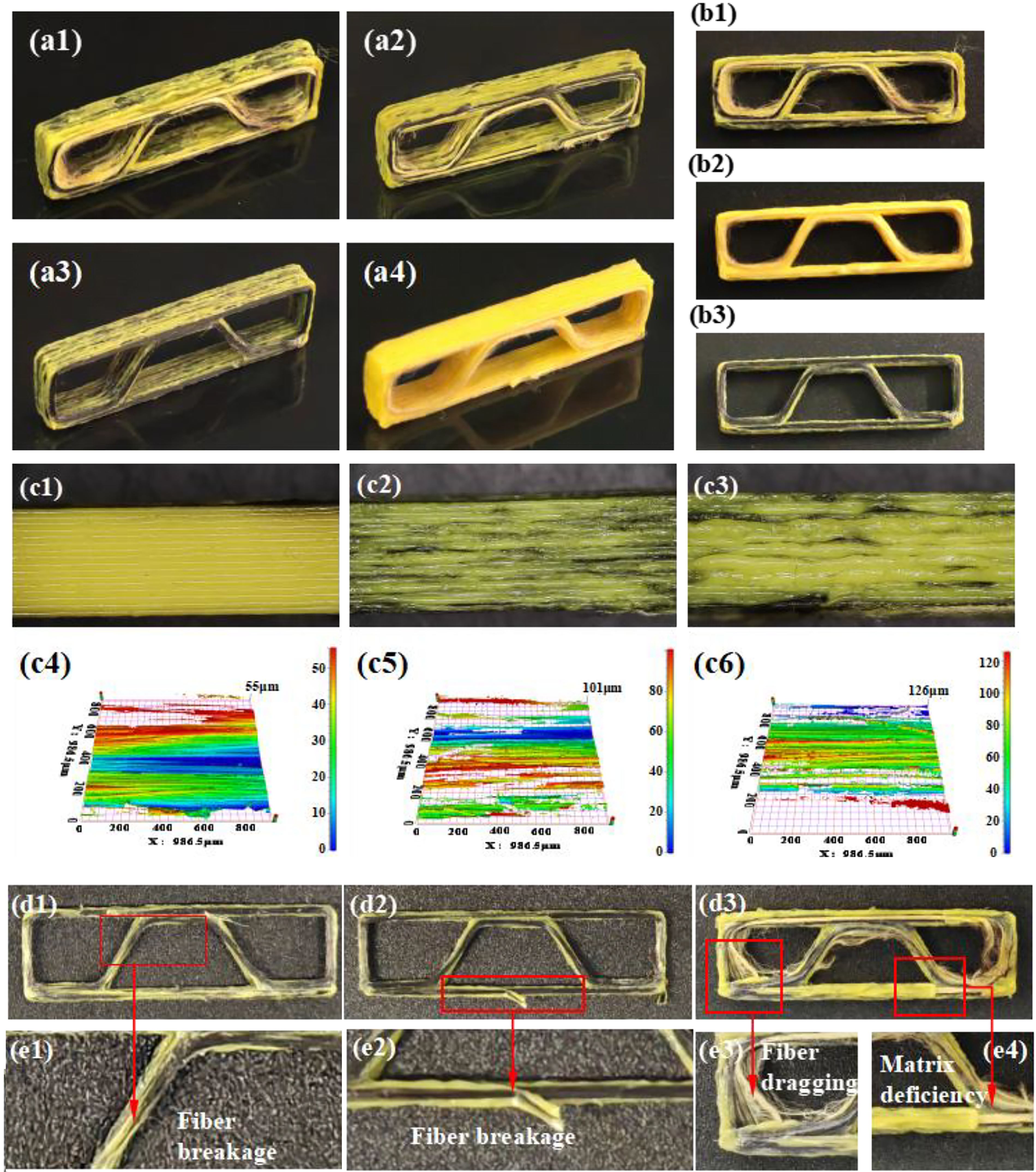
As shown in Figure 3(a1), when the speed reaches 120 mm/min, CFRP fails in printing due to rapid wear and breakage, but the HFRP can be printed successfully. This is because during the printing process, Kevlar fiber can reduce friction and stress concentration on carbon fiber and play a “protective role” as shown in Figure 3(a2). As shown in Figure 3(b1), CFRP samples fail to complete printing due to breakage at a speed of 120 mm/min, while HFRP could still be successfully printed under the same conditions. This protective mechanism not only prevents carbon fibers from complete breakage through Kevlar fibers but also ensures smooth printing progress by allowing partially fractured carbon fibers to be reprinted, as demonstrated in Figure 3(b2).
For hybrid fibers, due to the large number of printing directions, the relative positions of carbon fiber and Kevlar fiber at the nozzle will change, which can be roughly divided into three forms. Status I: the surface of carbon fiber contacts the nozzle (see Fig. 3(b1)). Status II: Kevlar fiber contacts the nozzle, as shown in Fig. 3(b2). Status III: two fibers contact the nozzle together or contact in different proportions, as shown in Fig. 3(b3). Generally, status III is a more common form, so the protective effect of Kevlar fiber on carbon fiber will also change. The following is a detailed analysis of these three states.
Status I
When carbon fiber is in contact with the nozzle, at this time carbon fiber is relatively more likely to break. However, since Kevlar fiber will not break, carbon fiber and Kevlar fiber are closely attached to the nozzle. Even if the carbon fiber breaks, the Kevlar fiber can still bring out the carbon fiber again through friction. Figure 3(d3) shows this situation. After the carbon fiber breaks, the carbon fiber in the subsequent path can still be printed normally.
Status II
When Kevlar fiber is in contact with the nozzle, this situation can protect carbon fiber to the greatest extent and prevent carbon fiber from breaking. Figure 3(c1–c2) shows the cross-section corresponding to Status II, and Figure 3(d2) shows Status II in the surface direction.
Status III
When both fibers are in contact with the nozzle at the same time, the carbon fiber may break partially first, but then the Kevlar fiber will directly contact the nozzle and protect the remaining carbon fiber. Figure 3(c3) shows this situation from the cross-section. It can be found that the proportion of carbon fiber is smaller than that of Kevlar fiber, which indicates that a partial fracture has occurred. Figure 3(d1) and (d4) show status III from the front.
Currently, the reason for carbon fiber breakage is the relatively large shear force existing at the nozzle. The addition of Kevlar fiber enables the hybrid fibers to exhibit relatively strong shear resistance. This ability can ensure that the carbon fiber does not have to bear the friction at the nozzle completely, thus enhancing the toughness of the carbon fiber.
Results and Analysis on Mechanical Behaviors
Crushing mechanical responses
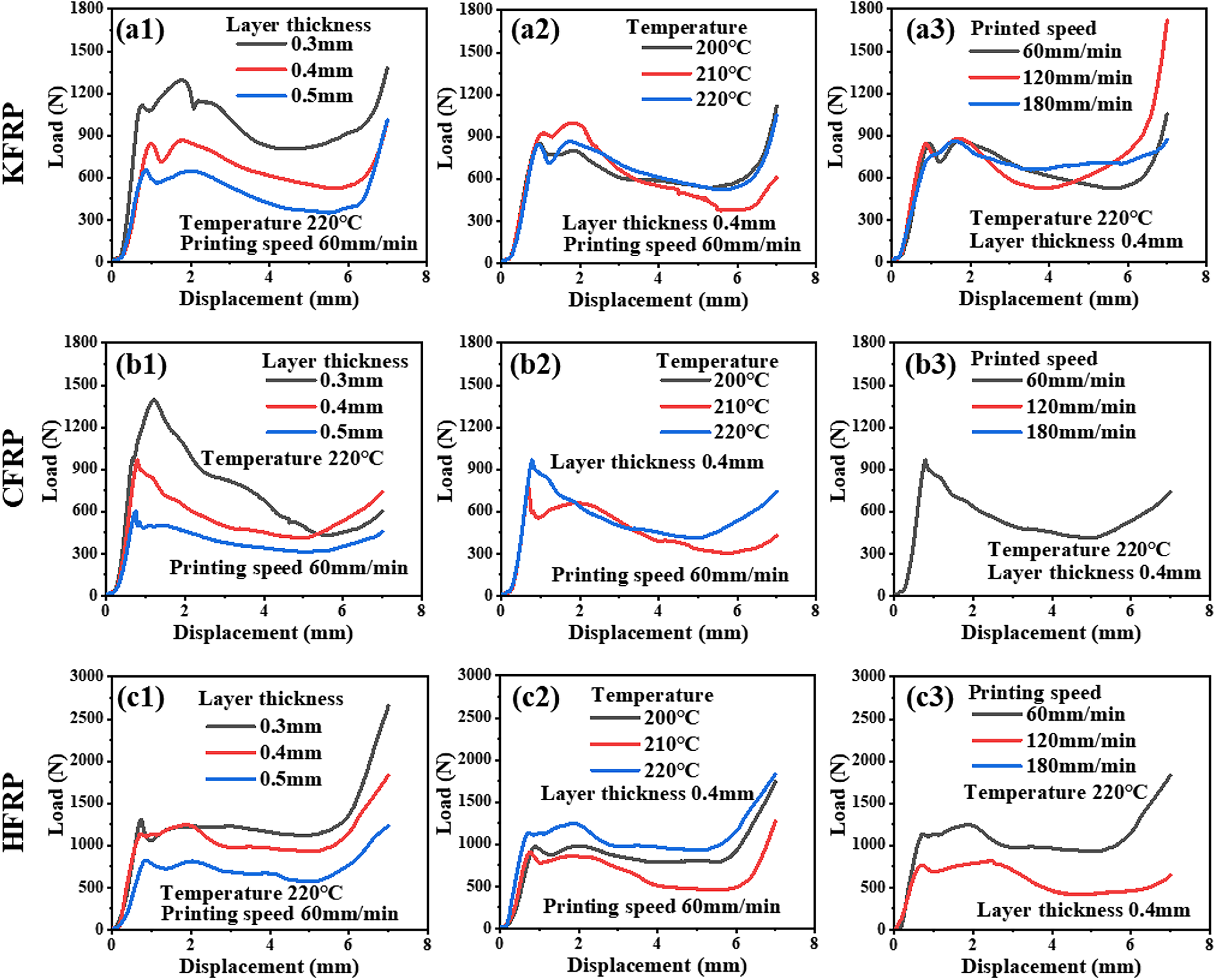
Figure 4 shows the crushing load–displacement curves of KFRP, CFRP, and HFRP corrugated sandwich structures corresponding to different 3D printing process parameters. In Figure 4(a1–a3), there are typically two peak loads in the load–displacement curve for KFRP. After the second peak load, the load–displacement curve undergoes a rapid decline stage. Then it drops to a relatively stable numerical level.
The crush load–displacement curves of KFRP, CFRP, and HFRP corrugated sandwich structures corresponding to different 3D printing process parameters.
As shown in Figure 4(b1–b3), different from KFRP, CFPR has only one peak in its load–displacement curves. It can be observed that the curve shows a sudden drop after the peak. This is because the main failure mode of CFRP is usually a brittle fracture. Once this kind of fracture occurs, its compressive capacity will be greatly damaged. Therefore, CFRP corrugated sandwich structures also show lower load efficiency during the crushing process.
As shown in Figure 4(c1–c3), the load–displacement curve of HFRP also has two peak loads. This is mainly because the HFRP contains Kevlar fiber and carbon fiber. However, it is different from single fibers. When the compressive displacement approaches the peak value, its structure can still maintain a relatively high load resistance level. From the perspective of the entire response process, the corrugated sandwich structure of HFRP has good load-bearing stability.
Effects of 3D printing process parameters
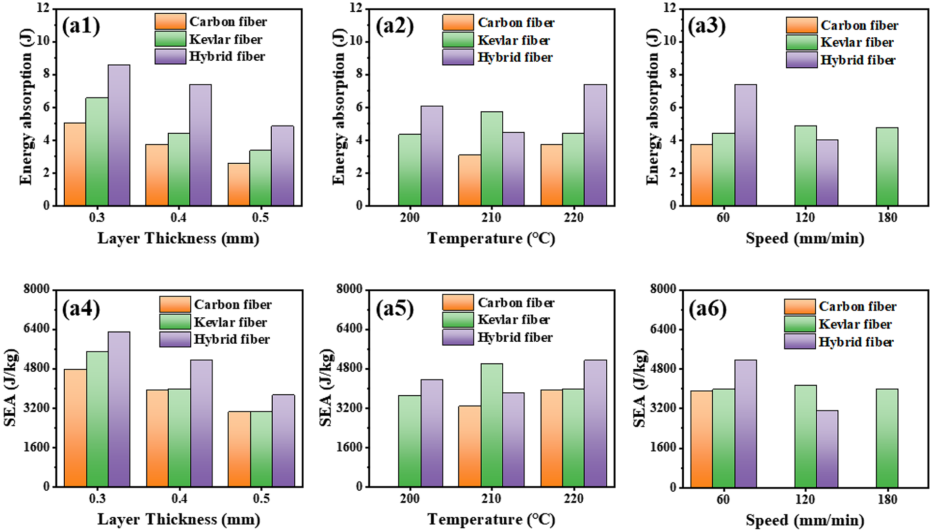
Figure 5 shows the comparison of mechanical properties of composite corrugated sandwich structures corresponding to different 3D printing process parameters. For CFRP, KFRP, and HFRP corrugated sandwich structures at 60 mm/min and 220°C, as the layer thickness continues to increase, their EA all show a gradually decreasing trend, the lower layer has better interlayer bonding strength and fiber content.
Comparison of mechanical properties of composite corrugated sandwich structures corresponding to different 3D printing process parameters.
When printed at 0.4 mm layer thickness and 220°C, the KFRP structure can be printed successfully at all speeds, but speed has very little impact on its mechanical properties, while CFRP structure only prints successfully at 60 mm/min. For the HFRP structure, when the speed increases from 60 mm/min to 120 mm/min, its EA value decreased by 46%, which shows that the sensitivity of different fibers to velocity is different.
In addition, temperature is also one of the important factors that has an important influence on the CFRP structure. When the layer thickness is 0.4 mm and the printing speed is 60 mm/min, CFRP is successfully printed only at temperatures of 210°C and 220°C. Moreover, the higher the printing temperature, the better the corresponding mechanical properties. The KFRP structure has the highest EA at 210°C. The mechanical properties of the HFRP structure also increase with the increase in temperature, which indicates that the impregnation rate is likely to be the key to affecting the mechanical properties of the HFRP structure.
Comparison among carbon, Kevlar and hybrid carbon/Kevlar
CFRP, KFRP, and HFRP samples are compared and analyzed, as shown in Figure 5. In terms of EA, it can be found that due to the toughness provided by Kevlar fibers, the EA of HFRP and KFRP is higher than that of CFRP. Meanwhile, under most process parameter conditions, HFRP exhibits higher EA characteristics than single fibers. This is because after fiber mixing, carbon fibers provide a higher peak load for the entire structure, while Kevlar fibers endow high toughness. The synergistic effect of the two makes the structure have a higher EA value. However, different results may occur under mismatched process parameters. For example, in sample no. 5, compared to the KFRP, the HFRP exhibits better EA values. However, in sample no. 6, the EA of KFRP is greater than that of HFRP. This indicates that different fibers have different sensitivities to 3D-printing process parameters, and it is found that HFRP is more affected by speed changes, which causes the problem of insufficient impregnation. Therefore, for the design and manufacturing of HFRP samples, it is necessary to simultaneously consider the influence of process parameters to achieve the best results.
Crushing failure process and modes
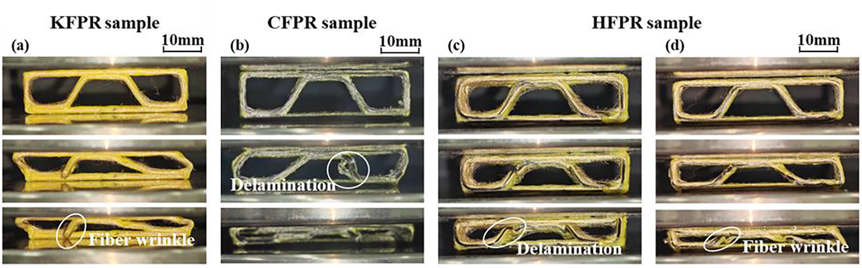
The failure modes of single fiber and hybrid fiber are compared to further explain the hybrid mechanism, and representative failure modes in the compression process are selected for analysis. Figure 6 shows the crushing failure processes of KFRP, CFRP, and HFRP corrugated sandwich structures under different 3D printing process parameters. As shown in Figure 6(a), the KFRP sample shows local outward buckling due to interlayer failure problems. The CFRP with process parameter no. 5 shows obvious in-plane delamination failure, as shown in Figure 6(b). For HFRP corrugated sandwich structures, extremely complex failure phenomena will occur during the crushing process, and buckling and interlayer delamination are more obvious, as shown in Figure 6(c) and (d). The specific analysis is as follows.
The crushing failure processes of KFRP, CFRP, and HFRP corrugated sandwich structures.
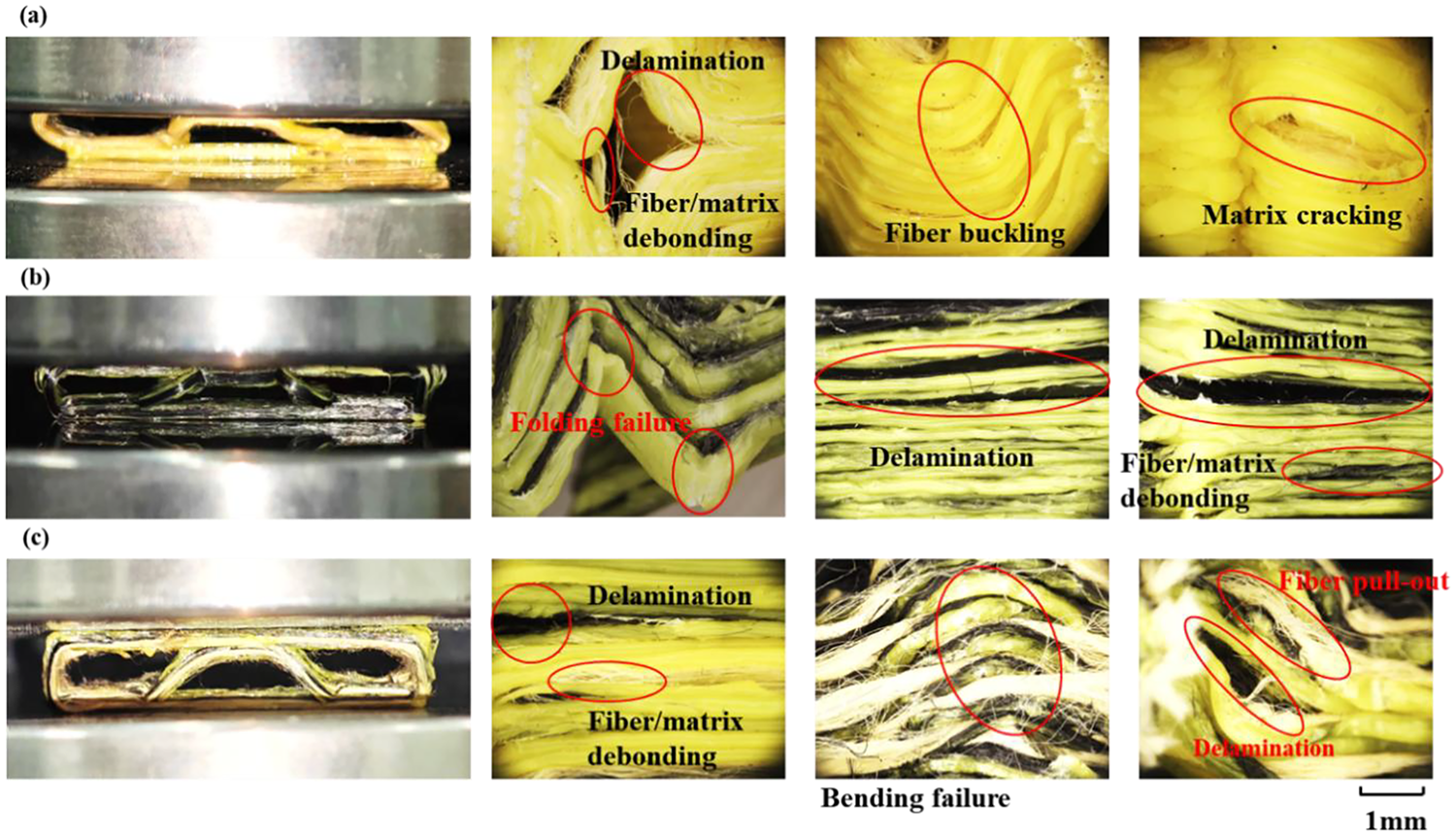
Figure 7 shows the typical failure modes in CFRP, KFRP, and HFRP. In Figure 7(a), it can be found that the crushing failure modes of KFRP corrugated sandwich structures mainly include delamination, fiber buckling, matrix fracture, and fiber/matrix debonding failure, among which the buckling phenomenon of KFRP is particularly significant. As shown in Figure 7(b), it can be observed that CFRP corrugated sandwich structures are mainly characterized by folding failure and interlayer delamination, and the folding failure is mainly due to the brittle fracture characteristics of carbon fiber. The degree of bending in this failure mode is more severe than the bending failure of HFRP, as shown in Figure 7(c), usually accompanied by matrix cracking. For the HFRP corrugated sandwich structure, relatively diverse failure modes are shown, such as interlayer delamination, bending failure, and fiber pull-out. Due to the poor interfacial bonding ability of fiber/matrix, HFRP structures are more prone to fiber pull-out, which is caused by poor fiber impregnation. 40
Typical failure modes of composite corrugated sandwich structures.
Hybridization mechanism on mechanical properties
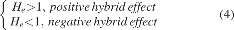
The hybrid effect coefficient is a key indicator for evaluating the mechanical properties of printed samples of hybrid fiber composite materials, and its principle is as follows.

Where
Evaluation criteria are as follows:
Since there are only four samples in which the three fibers are successfully printed simultaneously (the process parameters are nos. 1, 2, 3, and 5, respectively), the process parameters of these four samples are used to evaluate the hybrid effect of the fibers. The calculation of the four hybrid effect coefficients can obtain the data as shown in Table 4.
Hybrid Effect of Different Parameters
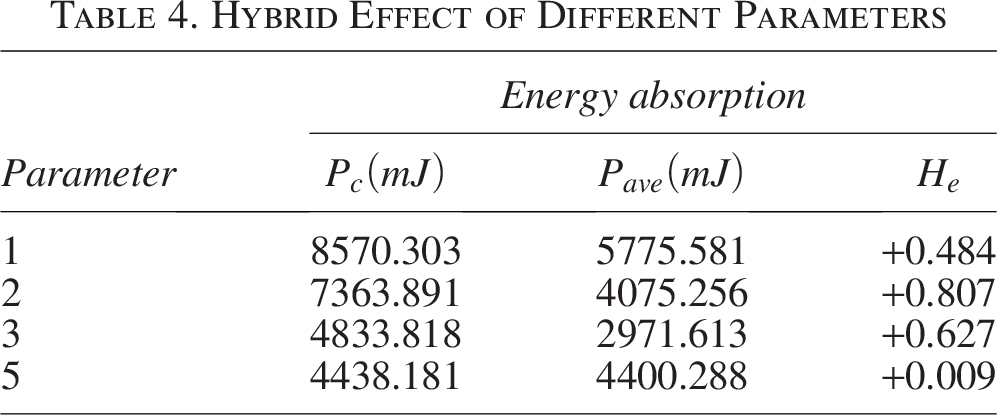
In terms of EA, the values of the hybrid effect coefficients under the process parameters nos. 1, 2, and 3 reach a relatively high level. Under the process parameter no. 5, its hybrid effect coefficient is close to 0, which further verifies that the temperature has a greater influence on the printing of hybrid fibers. Based on the above analysis, it is obvious that hybrid fibers have successfully gathered the advantages of both fibers in high load and fracture resistance, showing more comprehensive and excellent performance.
Conclusions
This study mainly explores the additive manufacturing process and mechanical properties of CFRP/KFRP corrugated sandwich structures by experimental method. There are many discoveries regarding this complicated issue, and the important conclusions and findings are drawn as follows.
3D-printing parameters have a significant impact on the quality of the HFRP sample, with the main issue being parameter compatibility. Due to the differences in optimal printing temperature, layer thickness, extrusion amount, line spacing, and speed between carbon and Kevlar fiber, it becomes difficult to adjust the parameters to simultaneously meet the optimal process conditions of both fibers, resulting in poor printing quality, multiple defects, and rough surface morphology. There is a hybrid effect between carbon and Kevlar fiber in the additive manufacturing process, which may inhibit or promote the formation of defects. By reducing the corner printing speed and adopting pre-impregnation technology, the surface quality can be further optimized, thereby improving sample accuracy. Hybrid fiber 3D-printing has a significant protection mechanism. Kevlar fiber protects carbon fiber, preventing it from breaking. This enables relatively smooth printing and formation of brittle carbon fiber samples even at higher printing speeds or under different process parameters. This is mainly because high-toughness Kevlar fiber effectively improves its toughness when subjected to friction at the nozzle opening and has a traction effect on carbon fiber for smooth extraction and deposition. Hybrid samples have an obvious hybrid effect on mechanical properties. Under most 3D-printing process parameters, hybrid fibers show higher bearing capacity and EA capacity than single fibers. Fiber hybridization improves the brittle fracture behavior and still has good bearing capacity after the highest peak load of fracture. However, hybrid fibers have more fiber pull-out phenomena in failure mode, proving that improving fiber and resin impregnation rates is key to enhancing hybrid fiber 3D printing.
Authors’ Contributions
W.Z.: Writing—review and editing, investigation, and supervision. S.X.: Data curation, investigation, and writing—original draft. Z.X.: Investigation. Q.S.: Resources and investigation. Y.R.: Writing—review and editing, resources, and investigation. H.J.: Conceptualization, writing—review and editing, investigation, project administration, and supervision.
Footnotes
Author Disclosure Statement
The authors declared no potential conflicts of interest with respect to the research, authorship, and/or publication of this article.
Funding Information
This study received financial support from Guangdong Basic and Applied Basic Research Foundation (Nos. 2023A1515012177, 2024A1515010772), Foundation from the National Natural Science Foundation of China (No. 52172356), Natural Science Foundation of Chongqing (No. CSTB2024NSCQ-MSX0688), and Key R&D Program Project of Hubei Province (2024BAB053).