
Abstract
This article presents a streamlined design pipeline that emphasizes designer agency and human–robot collaboration within robotic clay additive manufacturing processes. We introduce novel hardware and software to produce high-resolution ceramic architectural components at scale. 3D printing of clay allows for increased geometric complexity, facilitating a design approach whereby materials are expensive but form is cheap. This technology shows transformative potential for the architectural design and construction industries, allowing for greater freedom in form generation and enhanced functional efficiency. In addition, extrusion-based additive manufacturing of clay—a historically significant architectural material with environmental benefits—shows promise in revitalizing and redefining this material in both ornamental and structural applications. However, several critical challenges remain in the integration of clay extrusion into architecture and construction. Key among these is the trade-off between scale and resolution and the limited avenues for designer input and intervention during production. This article aims to address these challenges by presenting integrated workflows that detail a two-step mechanical extrusion assembly and associated software packages for motor calibration. Furthermore, we present software that enables real-time designer-led toolpath adaptation. The proposed extruder system builds a two-step extruder assembly with decoupled control of the extrusion and feeding mechanisms, with precise mathematical calibration of each to expand the achievable range of scales and resolution in printed prototypes. In addition, we challenge the pursuit of fully automated robotic construction by highlighting opportunities for real-time designer input during production, thereby increasing designer agency in all phases of design. As a result of our integrative research, we describe a workflow for developing modularized extrusion assemblies for robotically controlled additive manufacturing. In addition, we release two Grasshopper components, Pulse Control and DynPath, that achieve motor calibration in modulated clay assemblies and real-time motion intervention during fabrication, respectively. Finally, we present printed assembly prototypes and their design possibilities in an integrative framework.
Introduction
Over the last decade, architectural-scale robotic extrusion of clay and other paste materials have gained significant attention, with projects showcasing potential for application in the design and construction industries.1B2 -8 The clay 3D printing industry features several key players (Supplementary Figure S1), demonstrating a range of extrusion mechanisms (Supplementary Figure S1). Vormvrij 3D and CERAMBOT utilize pneumatic pressure systems that rely on compressed air to extrude clay, making them suitable for large-scale applications. These systems require air compressors, which result in higher energy consumption and increased complexity. WASP demonstrates models with pneumatic systems as well as hybrid systems coupling pneumatic feeding and mechanical extrusion mechanisms (XL 400100). 3D Potter printers employ a single-step mechanical extrusion with greater precision. Eazo printers showcase several models featuring pneumatic-mechanical couplings (i.e., Eazo Potter Air) and two-step mechanical extrusion systems (i.e., Eazo Zero). In addition, some of these companies (WASP) have developed extruder systems designed to pair with robotic arms. However, none offer integrated solutions that comprehensively address synchronization with the robotic system or incorporate real-time designer input and feedback during the printing process. Despite a range of extrusion products, there are several outstanding challenges in the widespread integration of robotic clay extrusion in architectural construction; namely, the tradeoff between scale and resolution in extrusion-based printing, material unpredictability and consequent print failures, and lack of streamlined intervention and error fixing processes to address this.
Robosense 3.0 presents a workflow for the fabrication of a robotically mounted clay extruder assembly and control software with the aim to advance high-fidelity clay extrusion at scale by centering system modularity and real-time designer feedback. We interrogate the possibilities of paste deposition-based robotic extrusion of clay by posing the question: how do we design and implement adaptable fabrication set-ups for high fidelity, multiscale, and multiresolution clay extrusion?
In response, we explore a robotically mounted modular extrusion assembly, utilizing two independently controlled motors for extrusion. Furthermore, recognizing the material unpredictability in clay extrusion-based fabrication, we investigate an alternative to a fully automated approach by leveraging the potential of human–robot collaboration. Real-time designer feedback in 3D printing is crucial for enhancing both the design and fabrication phases. During the early design stage, real-time feedback allows for rapid iteration, enabling designers to make immediate adjustments and optimize prototypes efficiently, In the later stages of fabrication, in situ designer monitoring could cause defects and geometric distortions in real-time, ensuring the quality of the final product and reducing waste.9B10 -12 We emphasize the critical role of real-time designer input and intervention, arguing integrative human–robot collaboration for error handling and active design adaptation are essential components of additive manufacturing of clay. This approach aims to enhance the printing process through dynamic designer input, allowing for adjustments and refinements during the build duration.
Robosense 3.0 intersects three areas of design research: (1) Clay extrusion printing (or clay 3D printing), (2) robotic fabrication, and (3) human–robot collaboration in design. This work aims to address several state-of-the-art challenges within this intersection, specifically, (1) scale-resolution tradeoff in large-scale 3D printing, and (2) lack of workflows for real-time error handling and interactive design intervention.
Clay extrusion printing
The last decade is marked by the emergence of 3D printing technologies capable of printing clay, from industry tools to open-source research and assemblies 13 by Jonathan Keep, 14 Unfold, 15 and Tom Lauerman. Seminal projects including Casa Covina, Ceramic Morphologies, 16 Ceramic Components, 17 Ceramic Information Pavilion, 18 Clay Non Wovens, 19 Robotic Clay Printing of Non-Conventional Wall Components, 20 and 3D Printing of Clay for Decorative Architectural Applications 8 have shown versatility in scale, methodology, and application in clay 3D printing. Researchers have embraced this way of making to achieve geometric complexity in their designs, while also highlighting the importance of behavior and materiality of clay as an active informant of design and fabrication.13,21 The emergence of extrusion 3D printing has facilitated collaboration among art, academia, and industry spaces, in the exploration of tools and techniques, and has contributed to a broader conversation in materially informed design as well as designer collaboration in 3D printing. 13
Drawing on the cross-disciplinary advancements in this field, Abdallah and Estevez leverage cartesian clay extrusion systems in the fabrication of brick designs that optimize material efficiency, reduce construction complexity, and advance sustainability.21,22 They integrate biologically and materially informed computational design with digital fabrication to create a “Biodigital Clay Brick” that challenges the constraints of traditional orthogonal bricks, exploring scalable solutions despite the high costs of 3D printing technologies. 21
Gursoy’s work focuses on traces of making—traces that fabrication tools leave on the final form.13,23 In From Control to Uncertainty in 3D Printing with Clay, Gursoy investigates opportunities for design intervention within these traces, exploring real-time print interventions that inform a final form that diverges from its “digital master.” 13
Robotic motion control in clay extrusion printing
While cartesian clay extrusion systems were foundational in advancing digital clay research, they are limited to a layer-by-layer, planar approach to printing. The pursuit for increased geometric potential and integrative digital design marked the expansion in robotically driven clay extrusion systems.20,24 Industrial robots and cobots have large spans and are capable of achieving at least six axes of motion control, which increases the scale of achievable prototypes and expands geometric freedom and nonplanar approaches to additive manufacturing via material extrusion.24,25 These systems are crucial in enabling clay 3D printing at scale, allowing its integration in the architecture and construction industries.3,4 The robotic additive manufacturing increases avenues for toolpath design and control and integration of designer interactivity. In Augmented Materiality, Ryan Luke John emphasizes this technology as a new form of digital mediation capable of bridging the gap between human sensibilities and material properties in the design process. 26 In his work featuring robotically driven wax milling, John defies linear progressions from design to fabrication by implementing a motion control strategy that allows for real-time visualization of the robotic toolpath, paired with the ability for designer intervention to modify this toolpath, therefore the design.
Robotic extrusion of clay expands the potential for material and process-informed decision-making throughout the fabrication process, challenging the conventional view of digital fabrication as simply a tool for the translation of a digital model into physical form. Im and Alothman’s Responsive Spatial Print demonstrates a process for clay extrusion with real-time material surveying and self-correction. There is an emergence of projects that incorporate environmental sensing and feedback into robotic fabrication workflows.24,27 However, enabling real-time designer feedback within multiaxis robotic clay printing systems remains an important area of investigation. While industry products feature some real-time error handling capabilities that rely on designer intervention including real-time speed and extrusion rate adaptations, they forego opportunities for real-time toolpath design.
Feature size-scale trade off
A central issue in extrusion additive manufacturing, including robotically driven extrusion of clay is the tradeoff between feature size and scale. Many market extruders are set up to handle a narrow range of internal pressures and are therefore faced with a tradeoff between prototype scale and feature size.
For the purposes of this study, we define “scale” and “resolution” of clay prints as functions of total print volume (scale) and filament dimensions (resolution). “Fidelity” is defined through the comparative analysis of the printed prototype to the digitally intended prototype. High-fidelity prototypes have filament dimensions that conform to the nozzle diameter and overall dimensions that conform to the digitally modeled prototype. The filament deviation is dependent on more than one print parameter, including extruder and auger speed, Tool Center Point (TCP) speed, clay viscosity, and nozzle size.
Materials and Methods
Robotic tooling
Below, we describe the evolution of a modular parametric extruder assembly and supply analysis of our observations throughout its evolution. Clay extruding robotic arm (CERA) consists of three generations of clay extrusion assemblies designed to be mounted on an ABB IRB 4600 robotic arm (Supplementary Figure S2). All iterations of CERA are developed and manufactured in-house. The first generation constitutes a single-step pneumatic piston (Supplementary Figure S3). The second generation constitutes a single-step mechanical piston (Supplementary Figure S4) later upgraded to a parametric set-up involving a two-step extrusion powered by a mechanical piston with a conventional screw (Fig. 1).
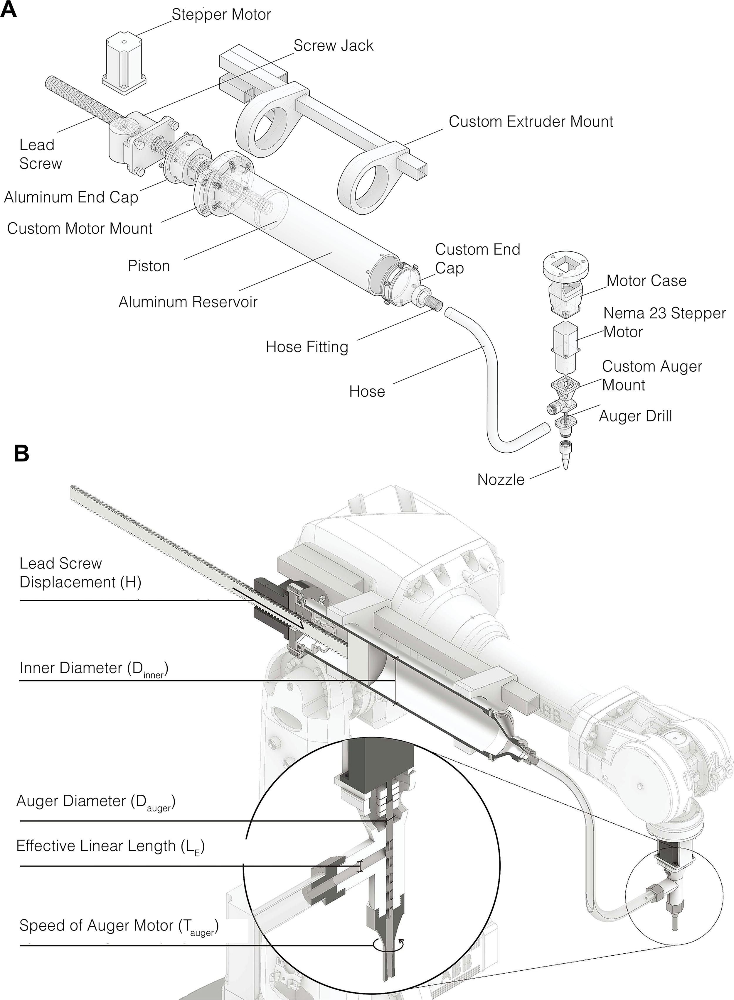
Extruder assembly: generation I and generation II
CERA III is the result of an iterative investigation of three generations of custom extruders, namely (1) a robotically mounted pneumatic mechanism (CERA I), a single-step mechanical mechanism (CERA II), and (3) a double-step mechanical extrusion mechanism (CERA III). CERA I is a pneumatic extrusion system whereby internal pressurization and subsequent clay extrusion are achieved through a manually controlled air pump. CERA I allows for little control over filament properties and demonstrates a narrow range of achievable scale and resolution (Supplementary Figure S5). CERA II addresses these shortcomings through the implementation of a single-step mechanical piston system whereby extrusion is achieved through a linear motion of a lead screw and piston assembly (Supplementary Figure S4).
While the extrusion mechanism is comparable to industry extruders such as PotterBot 3D, this system distinctively enables automated digital control of both the robot motion through either RobotStudio or Machina Bridge and the motor through Firefly for Grasshopper. As such, increased control over the calibration of the two movements can be achieved. This extruder generation improves filament bead precision and allows real-time adaptation of print and extrusion speed, yet lacks a robust start–stop sequence, with scale and resolution constrained by pressure differentials, clay viscosity, and internal friction limiting nozzle size and extrusion speed.
Cera III
CERA III is a two-step extruder assembly consisting of separately controlled feeding and extrusion systems. The feeding system achieves the transport of material from the reservoir into the nozzle, while the extrusion system controls material motion out of the nozzle. The extrusion system consists of an auger, a stepper motor, and their casings. The feeding system consists of a stepper motor (NEMA model), a screw jack gearbox, and a corresponding mount. The overall assembly includes a reservoir, piston, and lead screw (Fig. 1A). The utilized DC motor (NEMA 32) is a hybrid closed-loop stepper motor. It drives the Worm Gear Screw Jack, which converts the motor’s rotary motion to linear motion. This drives the motion of the lead screw and the piston. Worm Gear’s 1 to 12 reducer ratio creates sufficient torque to overcome the resistance from compressing the clay with less moisture. To achieve a high range of extrusion speeds while maintaining high torque for smooth extrusion, the extruder design requires real-time control of the rotary motion speed of the clay compressor motor (NEMA 32). Due to shortcomings of a regular stepper motor with an open-loop control system, such as losing steps during development, a hybrid stepper motor with a closed-loop control system is developed. This satisfies the demand for continuous material extrusion. In addition, a hybrid closed-loop stepper motor stops on its own in case of excessive resistance, which prevents damage to the system. The auger setup is attached at the robot’s sixth axis. A 1/4” fiberglass hose connects the auger attachment and clay reservoir and feeds the clay into the auger attachment. Extrusion is driven by a NEMA 23 stepper motor.
Electronic control
We use a command computer to control all components of the system including the robot toolpath motion and extrusion motors. An Arduino board (Supplementary Figure S6) is connected to the computer through a serial port for receiving data. The firmware loaded to the Arduino board converts the input signal into corresponding angular or linear displacements for the motors. The three key parameters of both motors used in our system are controlled by electrical pulse signals, namely the angular movement, the rotary speed, and the rotary direction. The angular movement and speed of the motor are strictly proportional to the number of input pulses and the pulse-width modulation. The rotary direction corresponds to the energization sequence. The angular displacement is controlled by regulating the number of pulses to achieve accurate positioning. Each pulse corresponds to each subdivided angular displacement step. Higher subdivision on the step motor represents higher accuracy. In our system, both step motors are subdivided into 3200 steps for each 360-degree turn. Namely, each pulse drives the stepper motor to reach 0.1125 degrees of angular movement. Pulse width modulation is used to regulate the motor rotation speed. A higher pulse width leads to a slower rotation speed on the step motor. The pulse-width can be controlled in Grasshopper and sent to Arduino via serial port in real-time. A Grasshopper component is developed for this purpose, which is described in the later section. By changing the energization sequence, the direction of motor rotation is reversed. The worm gear screw jack amplifies torque generated to reach a certain level to extrude the clay from the clay reservoir and into the hose.
Parametric modeling for effective clay extrusion
To achieve a smooth clay extrusion from the nozzle and mitigate internal pressure, the volume of clay extruded per minute is equalized to the volume of clay fed into the hose. For this, a relationship needs to be established between the two motors in the system (Fig. 1B).
The cross-sectional area (S) of (Dinner) of the reservoir’s inner chamber, is calculated based on the inner diameter of the (Dinner) of the reservoir:
The volume of clay extruded from the reservoir per minute can be described as the piston lead screw linear displacement (H) multiplied by the inner cross-sectional area, namely:
The worm gearbox drives both the piston and lead screw linearly. Each rotation of the worm gear pushes the lead screw by distance (L). As we use a 1:12 worm gearbox to amplify the torque, each turn on the motor drives the lead screw for L/12. If the speed of the clay compressor motor is T Compressor (Turns per minute), then the total piston displacement is:
Therefore:
As the clay is compressed into the hose, the auger drill pushes out the same amount of clay through the nozzle. Therefore, the choice of the auger, especially the dimension of the auger flute and the effective helix length of the drill, will affect the rate of extrusion. In our configuration, we use an 8 mm diameter general-purpose twist drill with two flutes, where the pitch (P) of each flute is approximately 10 mm. The inner chamber of the auger case is 10 mm wide, making the effective linear length (LE) (Fig. 1B) of each auger flute to carry clay to be 10 mm long.
The cross-sectional area of the two flutes on the auger drill occupies approximately half of the total cross-section of the 8 mm auger drill. If the rotation speed of the auger motor is T auger (Turns per minute), the volume of clay extruded by the auger extruder per minute is:
Since the volume of clay extruded every minute equals the volume the compressor reservoir is feeding to the hose, we can conclude that:
Namely,
By substituting all known factors into this equation (H = 0.5 mm/turn, Dinner = 117 mm, Dauger = 8 mm, LE = 10 mm), it is concluded that to achieve a smooth extrusion, the proportional relations between the auger’s and compressor’s motor speed (turns per minute) are approximately 22:1. Each turn on the clay compressor motor will need 22 turns on the auger motor to achieve the clay volume balance. The calculations have been confirmed by a set of extrusion tests (Fig. 2).
Material design and calibration
While motor synchronization as explained in the previous section is important to achieve reliable clay deposition, various other speeds need to be calibrated to achieve high-quality prints. An effective ratio between TCP speed (LTCP) and extrusion speed is empirically identified in relation to clay body and viscosity. The calibration testing uses a 10:3 clay to water ratio of Georgie’s Cannon Beach Dry clay reinforced with synthetic fiberglass. Extrusion speed is defined as the length of clay material extruded per minute. Mathematically, the length of the clay material (LC) extruded from a nozzle per minute can be inferred by:
Where DN is the nozzle diameter.
For our clay body mixture, a matrix of tests (Fig. 2A) are done to determine the relationship between extrusion speed and TCP speed as it impacts filament quality. For these sets of tests, the clay body, nozzle diameter and layer height are kept constant.
Software development
Central to Robosense 3.0 is the development of comprehensive workflows for real-time changes in robot motion, toolpath, and extrusion rate. For this, a set of in-house Grasshopper components are developed: PulseControl 28 and DYNPath. 29
Real-time motor adjustments through pulse control
The PulseControl a component enables real-time adjustments of motor speed and direction during the clay extrusion process, offering fine-grained control to designers through Grasshopper. It converts integers into pulse frequency and energization sequences, allowing the designer to directly influence the motor’s rotor speed and direction. Inputs include the serial port’s index, on/off switch for the port, motor rotation speed (pulse frequency), and motor direction (energization sequence). By optimizing the Arduino firmware and conducting motor calibration, PulseControl achieves precise control, representing the motor speed as an absolute integer rather than a relative analog value. This ensures accurate motor turns per minute. In addition, a laser distance module sensor inside the extrusion reservoir prevents internal collisions.
DYNPath b offers a designer-centric approach to human–robot interaction within the clay 3D printing process. It works in conjunction with MACHINA and the MACHINA bridge to effectively transmit motion commands to the extruder system, leveraging MACHINA’s real-time control capabilities. Unlike traditional, noninteractive setups—such as those often facilitated by RobotStudio—where a print toolpath is sent as a fixed, immutable list of point frames for sequential execution, DYNPath offers a more dynamic approach. While RobotStudio excels at offline programming and simulation, allowing designer to fine-tune a complete sequence before execution, it lacks the ability to adjust paths during real-time operation. MACHINA, on the other hand, supports real-time command updates. DYNPath leverages this capability, allowing each point frame to be sent individually and adjusted in real time based on the ongoing process (Supplementary Figure S7). This means that within a DYNPath-enabled workflow, designers can make active design decisions between each point’s execution, allowing for flexibility to adapt to changes or correct for unexpected conditions during the 3D printing process. Unlike existing systems that rely heavily on vision-based sensors or automated corrections, DYNPath emphasizes real-time designer control through a Python-based Grasshopper component. It enables designers to directly adjust the print path, parameters, and tool movements as the process unfolds (Supplementary Figure S8 and Supplementary Video S1). This level of control supports dynamic design decisions, making DYNPath particularly valuable for creative applications where designer input can adapt to variations in material behavior during printing.
In the DYNPath workflow (Fig. 3), the code execution begins when the TCP is positioned at the initial (first) point (pi) of the toolpath. Each subsequent point (pi+1) is transmitted after a set time interval, calculated as t0 = distance between point frames/TCP speed. Once time t0 has elapsed, the next point is transmitted to MACHINA for execution. Designers can adjust parameters like location or height during this interval and directly influence the toolpath. The DYNPath component features the inputs “initial point (i0)” and “toolpath points,” with possible functions including “offset curve,” “translate x,” “translate y,” “translate z,” and “TCP speed” to control respective point frame parameters. All points within the same layer are interconnected, meaning adjustments to a single point affect all remaining points in that layer. Designers can modify these inputs through Grasshopper at any time, continuously updating the list of execution points in response to their design decisions. This capability enables both real-time error handling (Fig. 4) and design interventions (Fig. 5) during the execution of a clay print.
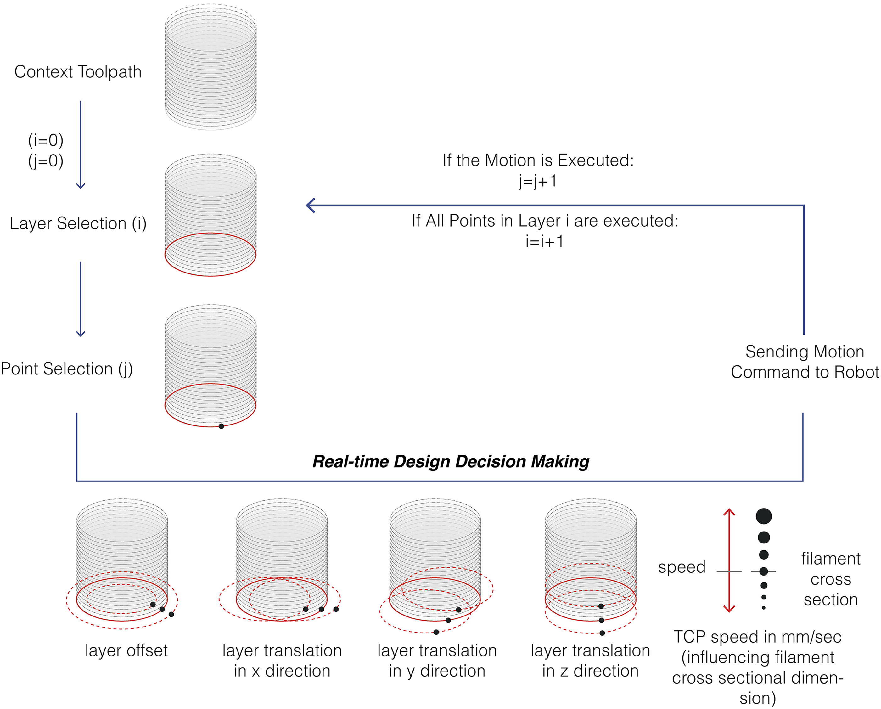
Workflow diagram of collaborative toolpathing demonstrating possibilities of real-time decision making such as layer offsetting, layer translation in the XYZ directions and TCP speed. 32 TCP, tool center point.
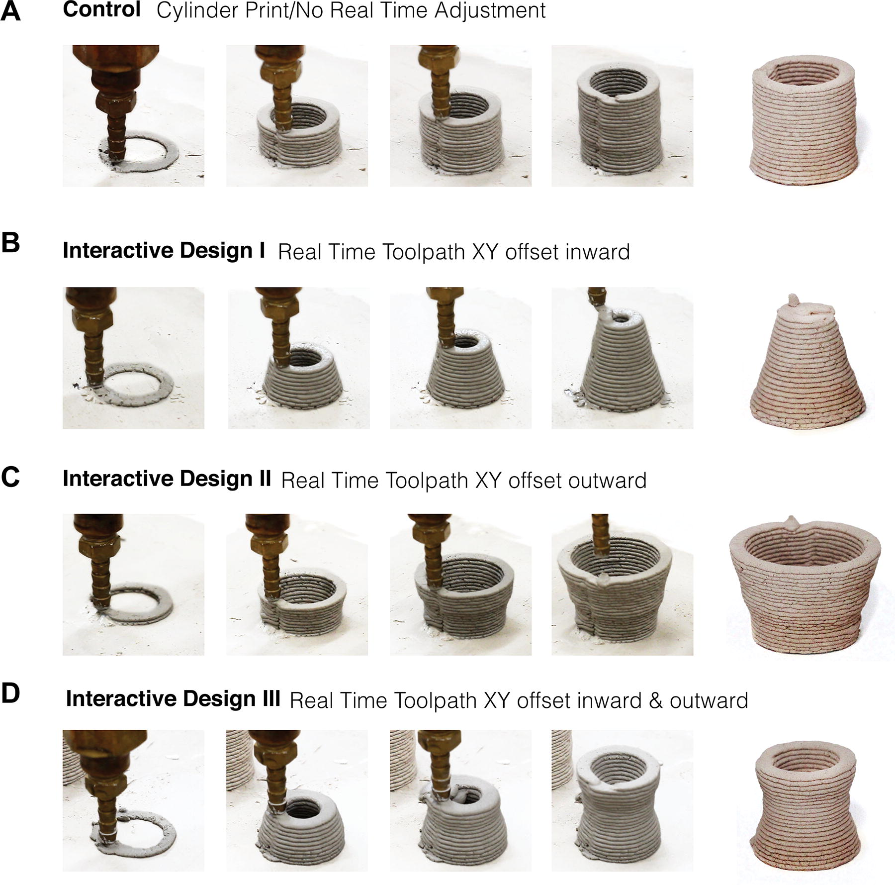
DYNPath uses predictive calculations to guide the robot’s movement, this approach ensures a smooth flow of commands, maintaining continuous operation. Although direct real-time feedback from MACHINA 30 was explored, delays in response limited its effectiveness for immediate adjustments. This highlights the strength of DYNPath’s predictive model in maintaining consistent output while allowing for designer-driven changes. The approach offers a solid foundation for future integration of more advanced feedback mechanisms, aiming to enhance real-time responsiveness for even greater adaptability in creative projects. MACHINA enables real-time command execution, while DYNPath extends this by allowing designers to integrate design feedback directly into the printing process (Supplementary Video S2 and S3), adapting the path dynamically in response to changing environmental or material conditions, or as design input (Fig. 6).
Results and Discussion
In his work featuring robotically driven wax milling, 26 John defies linear progressions from design to fabrication by implementing a motion control strategy that allows for real-time visualization of the robotic toolpath, paired with the ability for designer intervention to modify this toolpath, therefore the design. CERA III demonstrates a similar dynamic set of relationships between the designer and robot, including real-time toolpath modifications and design updates for multiaxis clay 3D printing.
Extruder evolution
CERA III represents the culmination of three generations of large-scale clay extrusion attachments developed at JSLab. These iterations include a pneumatically driven extrusion assembly, a single-step mechanical extrusion assembly, CERA II, and the latest multi-step mechanical extrusion system, CERA III. We showcase various prototypes produced across three generations of our in-house extruders. Pneumatic extrusion produces clean, continuous filaments but lacks precise control over filament start/stop due to unregulated pressure, limiting complex geometries such as lattices and arches. CERA II improves on this with a mechanically driven system, enabling better calibration between extrusion rate and robotic motion through Grasshopper components. However, pressure control remains limited, limiting effective start/stop sequences and reducing precision in certain geometries. Although CERA II’s extrusion technology is parallel to 3D PotterBot, it is able to achieve enhanced toolpath freedom through robotic toolpath execution.
While CERA III retains the core components of its predecessor, several enhancements have been introduced to reduce internal strain. These improvements mitigate common failure mechanisms associated with large-scale clay extrusion, such as pressure-induced malfunctions, and an expanded range of nozzle diameters that can be used without compromising the material flow. This design allows for a broader range of deployable nozzle diameters (Fig. 2B).
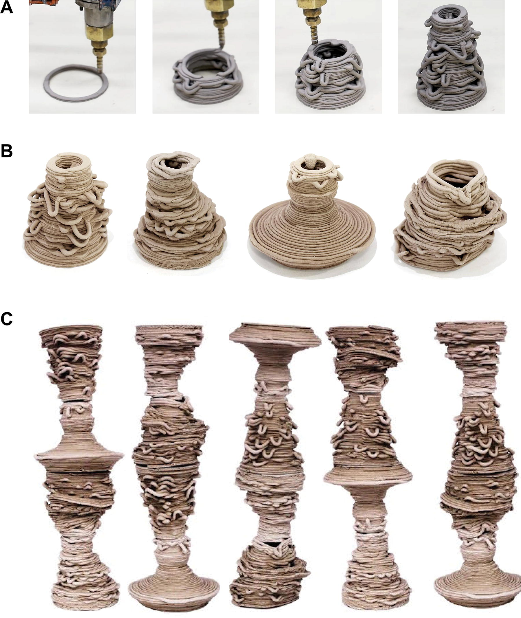
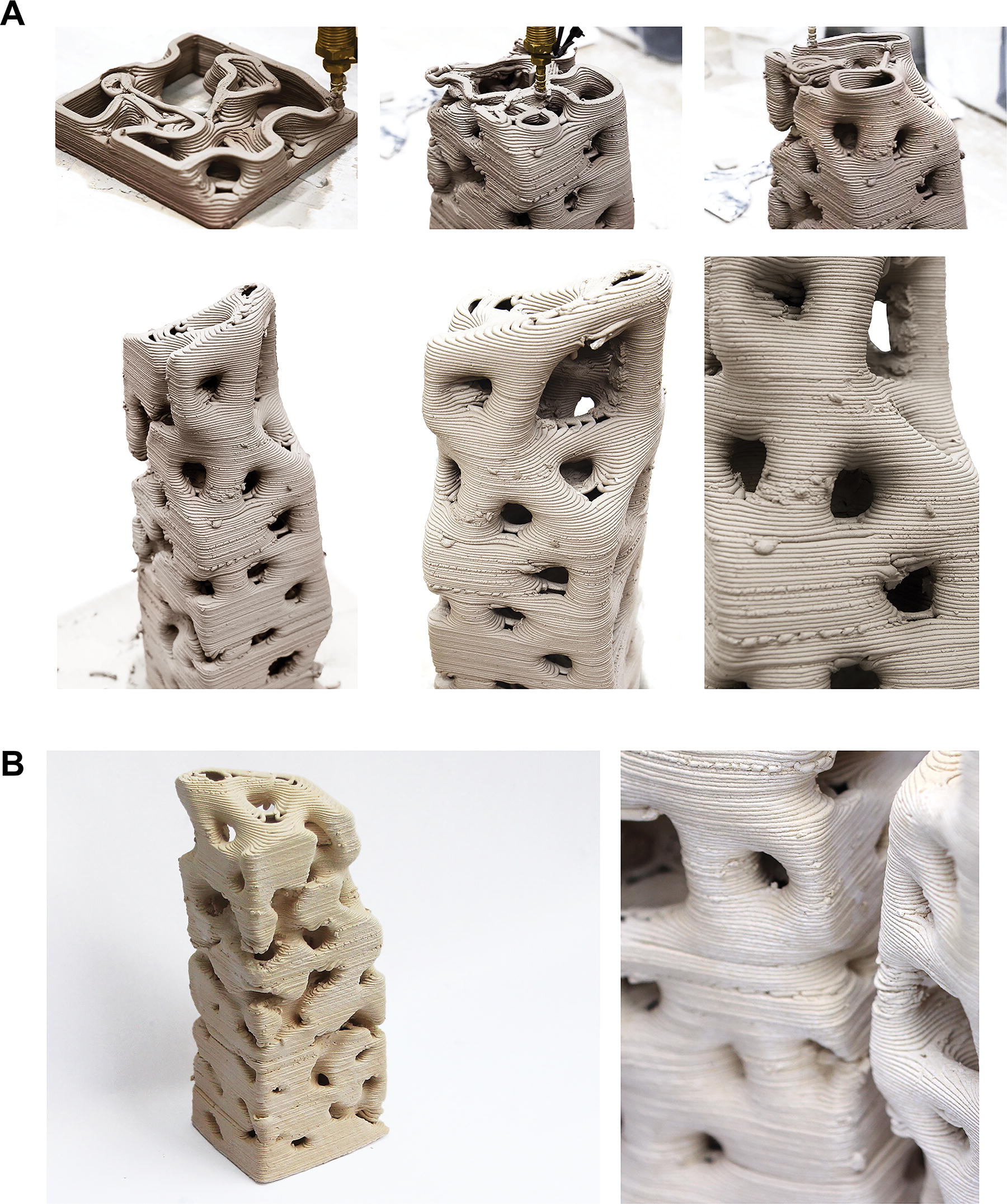
The parametric assembly of CERA III motors, combined with TCP speed control, allows for fine-scale control over filament properties. The efficient start/stop sequence from controlled internal pressure enables greater geometric possibilities. Thus, CERA III achieves versatile and complex, prototypes, such as a porous bioinspired lattice geometry, PolyBrick 2.0 (Fig. 7, Supplementary Video S4), and nonplanar scutoid modules (Fig. 8).
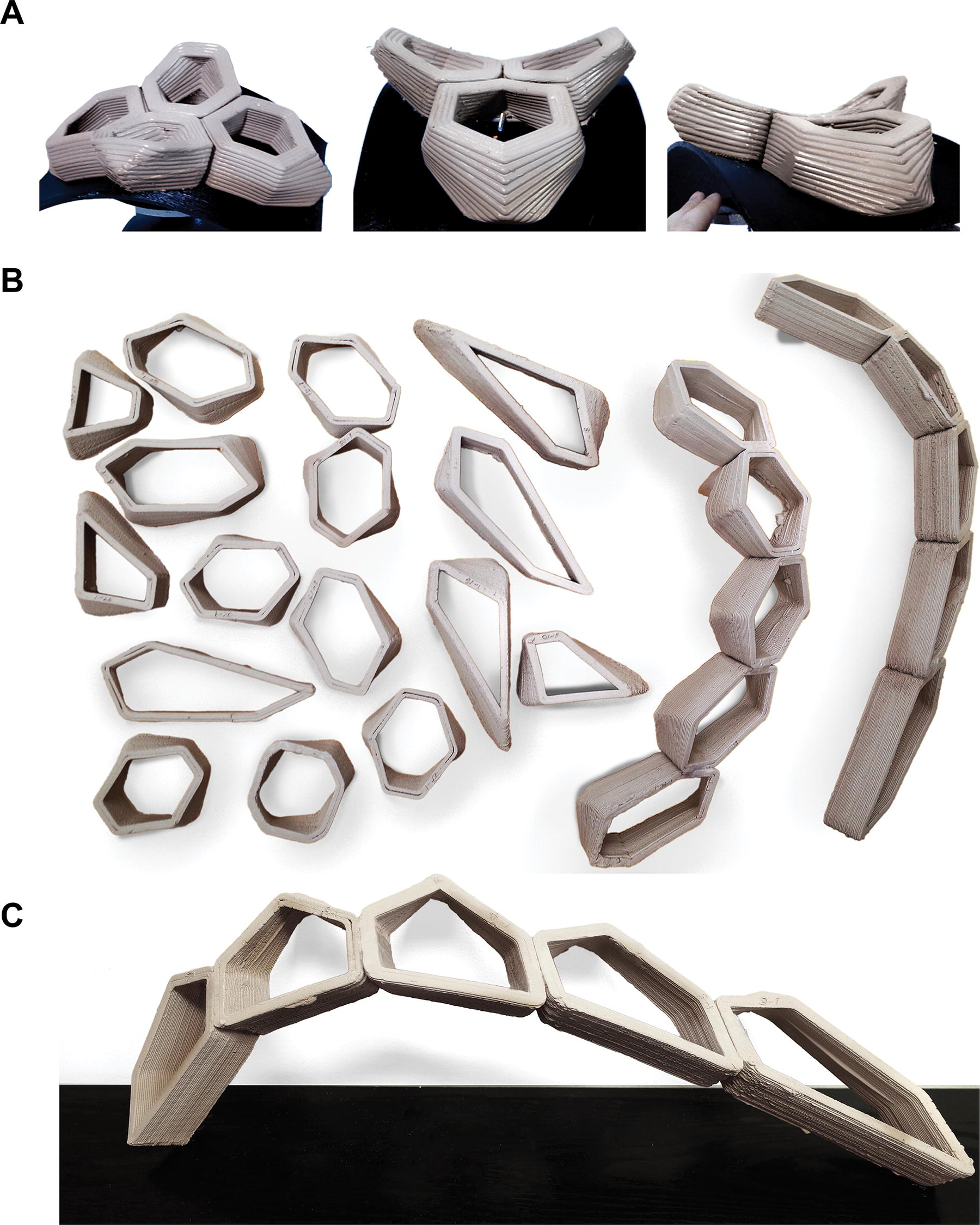
Process photos of nonplanar printing of scutoid prototypes showcasing the toolpath capacity of robotically mounted clay extrusion system, particularly leveraging the robotic range of motion. 33
Real-Time error handling and robotic collaborative design
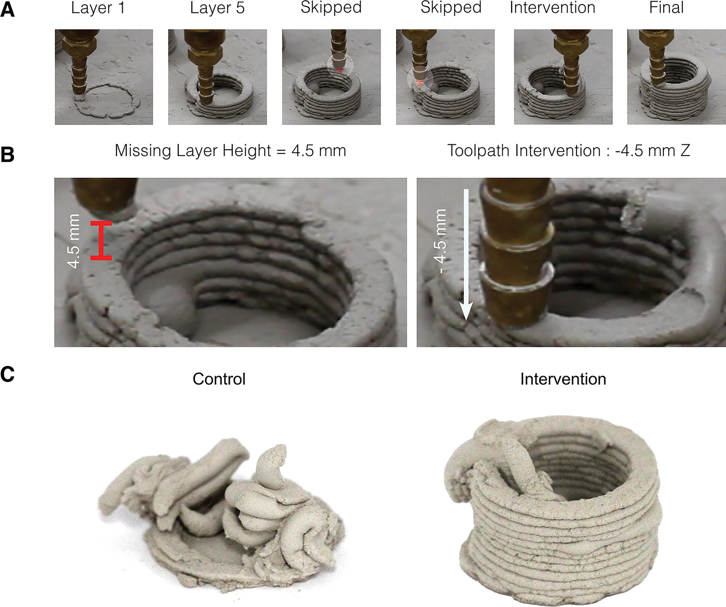
In additive manufacturing of clay, where print variability and extrusion errors are often encountered, integration of workflows that enable and encourage real-time designer intervention to the print process are crucial. One mechanism of print failure in clay extrusion printing is uneven extrusion and occasional layer skipping, typically caused by nozzle clogs from material hardening or imperfections. Some commercial products, such as PotterBot have limited built-in options to address real-time issues such as increasing/decreasing extrusion rate or speed. Real-time intervention and error handling are implemented utilizing the described DYNPath plug-in. This allows for X, Y, and Z-axis adjustments during the print process (Supplementary Figure S8). Moving the nozzle downward to compensate for skipped layers during printing allows for a smooth and rapid continuation of the print process. Figure 4 compares print results of a prototype in which layer skipping has occurred during the print process. Without designer intervention print failure is observed. Following real-time intervention and Z-axis adjustment, a successful print is obtained.
CERA III distinguishes itself from industry clay extruders such as PotterBot in its ability to facilitate non-planar toolpaths within a large build volume. Furthermore, it is distinct from two-step industry extruders such as WASP extruders in its capacity to execute real-time designer input and intervention. The current setup excels in scenarios where designers need direct control and flexibility in real-time, introducing a highly interactive environment for creative projects (Supplementary Video S3 and S4) to clay additive manufacturing. While there are several projects that feature real-time designer input in additive manufacturing and robotic construction,9,26 the novelty of this work is in the integration of the workflow with robotic additive manufacturing of clay. Building on this, future developments could further elevate the system’s adaptability, making it even more responsive and dynamic for a broader range of applications.
Conclusion
With this research, we challenge fully automated robotic construction by providing a model for collaborative and adaptive clay printing. We develop comprehensive workflows to enable the exploration of the formal and material capabilities of clay 3D printing. By understanding the systems of clay extrusion within interconnected trajectories of research, namely, scalable extruder assembly, material design and calibration, fabrication-aware extrusion toolpathing, and real-time collaboration and control, we propose workflows that have potential to increase the ease of application of this fabrication process. Hence, the advantages of clay 3D printing can be fully implemented across various industries and hold great potential for human–robot collaboration within this type of fabrication process.
One of the central challenges in scaling clay extrusion for architectural purposes is achieving high fidelity across varying scales, while addressing issues of material unpredictability inherent to paste-based fabrication processes. Traditional pneumatic systems, like those utilized by Vormvrij 3D and CERAMBOT, require pressurization systems with (e.g., air compressors), high energy consumption and limited adaptability. WASP and Eazo systems, which have two-step mechanical models, as well as models that combine pneumatic and mechanical components, have made strides in a more controlled extrusion but have yet to integrate real-time control and designer feedback, limiting their dynamic capabilities. CERA III presents workflows that mitigate listed challenges by leveraging a decoupled and parametric mechanical extrusion system, allowing enhanced precision and adaptability.
Figures 6 to 8 show the preview of projects developed by students in the JSLab using CERA III: PolyBrick 2.0 by Eda Begum Birol,30,31 Digital Impromptu by Mahshid Moghadasi, 32 and Interactive Fabrication and Design of Bioinspired Surface Geometry by Teng Teng. 33 Furthermore, the extrusion system is constantly under review, with upgrades made to both hardware and software of the system, in accordance with the requirements of new projects executed in the laboratory.
Footnotes
Authors’ Contributions
E.B.B., T.T., and M.M. conceptualized, curated data, performed formal analysis, developed methodology, software, and hardware, visualized results, and wrote the original draft. K.G. curated data, performed formal analysis, developed methodology, and worked on hardware. A.A., K.P., and V.V. performed formal analysis, developed methodology, worked on hardware and materials design, and visualized results. J.S. curated data, developed methodology, conceptualized, supervised, investigated, provided resources, reviewed, and edited the article.
Author Disclosure Statement
No competing financial interests exist.
Funding Information
This project is funded by the Jenny Sabin Lab and supported by the College of Architecture, Art, and Planning at Cornell University.
References
Supplementary Material
Please find the following supplemental material available below.
For Open Access articles published under a Creative Commons License, all supplemental material carries the same license as the article it is associated with.
For non-Open Access articles published, all supplemental material carries a non-exclusive license, and permission requests for re-use of supplemental material or any part of supplemental material shall be sent directly to the copyright owner as specified in the copyright notice associated with the article.