
Abstract
This article presents a novel methodology for the simultaneous optimization of both structural topology and printing path in 3D concrete printing (3DCP), addressing a critical gap between digital design and physical manufacturability. Unlike conventional sequential approaches, our framework is grounded in discrete frame structures, which inherently reflect the filament-based nature of 3DCP, thereby enhancing geometric and mechanical fidelity. The proposed formulation strategically leverages the inherent anisotropy of printed concrete by aligning the printing direction along the longitudinal axis of each frame member to maximize strength and material efficiency. Key manufacturing constraints are integrated directly into the optimization process: member widths are restricted to integer multiples of the nozzle size, and the printing path is enforced as a globally continuous, non-intersecting, and non-overlapping Eulerian circuit through a mixed-integer linear programming model. The efficacy of this simultaneous optimization approach is demonstrated through a series of benchmark problems, which confirm that the resulting designs not only satisfy strict structural displacement and stress constraints with minimal material usage but are also readily manufacturable via direct “one-stroke” printing. This work establishes a foundational integration of structural performance and manufacturability, paving the way for more efficient and reliable 3DCP applications.
Keywords
Introduction
3D concrete printing (3DCP), a burgeoning additive manufacturing technology, has revolutionized the construction of civil structures. 1 It extrudes cementitious materials 2 layer by layer, with each layer deposited through a nozzle filament by filament, offering exceptional flexibility in terms of free-form structures.3,4 This flexibility has been validated by the remarkable success of numerous large-scale building and bridge projects. 5 Furthermore, this flexibility offers a unique opportunity to enhance structural performance through optimization.
For 3DCP, two major optimization problems need to be studied: structural topology optimization and printing path optimization. The topology optimization is concerned with the optimal structural layout under the prescribed design conditions. The layout freedom can be well fulfilled by the constructional flexibility of 3DCP. Therefore, incorporating topology optimization technology into 3DCP structural design has attracted extensive attention. Vantyghem et al. 6 discussed three potential topology optimization techniques, that is, compliance, stress, and multi-physics, that are applicable to 3DCP. Later, they and coworkers made demonstrations of a post-tensioned 3DCP girder 7 and a 3DCP bridge 8 designed through topology optimization. Kinomura et al. 9 manufactured a topology optimized pedestrian bridge consisting of 44 prestressed 3DCP segments. Alabbasi et al. 10 fabricated optimized 3DCP columns for housing projects in Saudi Arabia. Li et al. 11 constructed a cable-supported composite 3DCP structure based on a multi-material topology optimization method.
In contrast, the path optimization is concerned with converting the virtually designed structural model into reality through feasible and efficient path planning of the nozzle. Several manufacturing constraints, such as path continuity, intersection, and overlapping, should be considered during this optimization to guarantee the printing quality. Currently, three strategies are widely used for the path planning 12 : direction-parallel paths (e.g., raster or zigzag path),13–15 contour-parallel paths (successive offsets of boundary contour),16,17 and space-filling curves (e.g., spiral, 18 Fermat spiral, 19 Hilbert path,20,21 or Hamiltonian path 22 ). Since almost all the strategies are derived from “hot-joint” additive manufacturing technologies for other materials such as thermoplastics and metals, their direct applicability to “cold-joint” 3DCP remains a challenge. Issues like path discontinuity, underfilling and overfilling caused by sharp turns, or self-intersection due to dimensional non-integer multiple of the nozzle size are inevitable when using a single strategy. Bi et al. 23 and Wan et al. 24 have elaborately discussed the advantages and disadvantages of each strategy for 3DCP. To optimize the printing path, one common solution is the combination of two or more strategies. 25 For instance, Bi et al. 23 first generated primary contours by double offset and outward contour schemes, then filled local underfilling areas by zigzag paths, and finally connected all paths into a globally continuous path. A post-processing optimization algorithm was further implemented to improve the overall smoothness of the path through local adjustment. This kind of hybrid methods is superior to the single strategy. However, the disadvantages inherited from the single strategy cannot be fully eliminated. Another solution is the adaptive path,24,26,27 which controls the extrusion parameters, such as the printing speed and the material extrusion rate, in process to vary filament size satisfying the planned non-uniform path. Due to the rheological complexity of printable concrete (being flowable within the printing system and solidifying quickly after deposition), this solution poses a high demand for the material mixture and the printing system.
The aforementioned studies explored the topology and path optimization separately. However, it is aware that there exists a gap between the topology optimized model and its manufacturing. On the one hand, the topology optimized design may have issues, such as non-smooth boundaries, dimensional non-integer multiple of the nozzle size, and non-uniform member sizes, that are infeasible for direct 3D printing and require further post-processing adjustment, which deviates from the original optimal design. On the other hand, the printing path produces anisotropic material properties, which are stronger in the printing direction compared with the transverse and stacking directions.28,29 The anisotropy affects the structural performance and has not been considered during the topology optimization, rendering the optimized design nonoptimal. Therefore, the topology optimization and the path optimization need to be integrated. Martens et al. 30 demonstrated that the material anisotropy and manufacturing constraints such as overhangs of 3DCP should be taken into account in the design optimization. Carstensen 31 and Fernández et al. 32 embedded the nozzle size constraint into the topology optimization. Pastore et al. 33 proposed a Bézier curve-based genetic algorithm to address the path continuity and nozzle size constraints. Bi et al. 34 addressed the material anisotropy and various manufacturing constraints, including self-support, printing path continuity, and domain segmentation, of 3DCP within the bidirectional evolutionary structural optimization framework. Jewett and Carstensen 35 considered both the nozzle size constraint and the weak inter-bead bonding. Mogra et al. 36 integrated buildability requirements during the printing process into the optimization problem. Yang et al. 37 and Yang et al. 38 proposed a topology optimization method integrated with the anisotropy, nozzle size, path continuity, and overhang angle constraints.
Nevertheless, the optimization studies above were based on continuum structures. As stated earlier, 3DCP extrudes materials filament by filament, and the adjacent filaments are cold jointed, forming clear interfaces. The geometric feature of the printed member is closer to discrete structures such as frames. More relevant discussions between the discrete and continuum topology optimization for additive manufacturing have been recently given by Carstensen et al. 39 Therefore, the optimization of 3DCP is to be tackled on the basis of discrete frame structures in this study. In doing so, naturally, the boundary of each member is smooth and the size of each member is uniform,39,40 which is potential for direct printing. In addition, a 3DCP methodology optimizing the structural topology and the printing path simultaneously, instead of optimizing the topology first and then generating the tool path, 40 is proposed. Although the concept of simultaneous optimization has been introduced for other additive manufacturing technologies,41–43 the difference between the cold-joint and hot-joint printing renders 3DCP unique. The proposed methodology utilizes the anisotropy of the printed material and the graph theory, 44 guaranteeing the mechanical efficiency of the optimized structure and the dimensional integer multiple of the nozzle size for the “one-stroke” path. The optimization problem is mathematically formulated as a mixed-integer linear program (MILP), which is readily solvable. The obtained structure is printable directly and efficiently.
The remainder of this article is organized as follows. First, the optimization problem for simultaneous topology and path optimization is mathematically formulated. Then, the optimization formulation is tested by a series of problems. The effectiveness of the simultaneous optimization needs verification. Finally, conclusion is drawn.
Problem Formulation
To optimize the structural topology and printing path of a frame simultaneously, this study follows the popular ground structure approach.39,45 The given design domain provided with appropriate boundary conditions and external loads is decomposed by often evenly distributed nodes, as illustrated in Figure 1. The link between two arbitrary nodes represents a potential frame member, and the ground structure is composed of all potential members within the design domain.
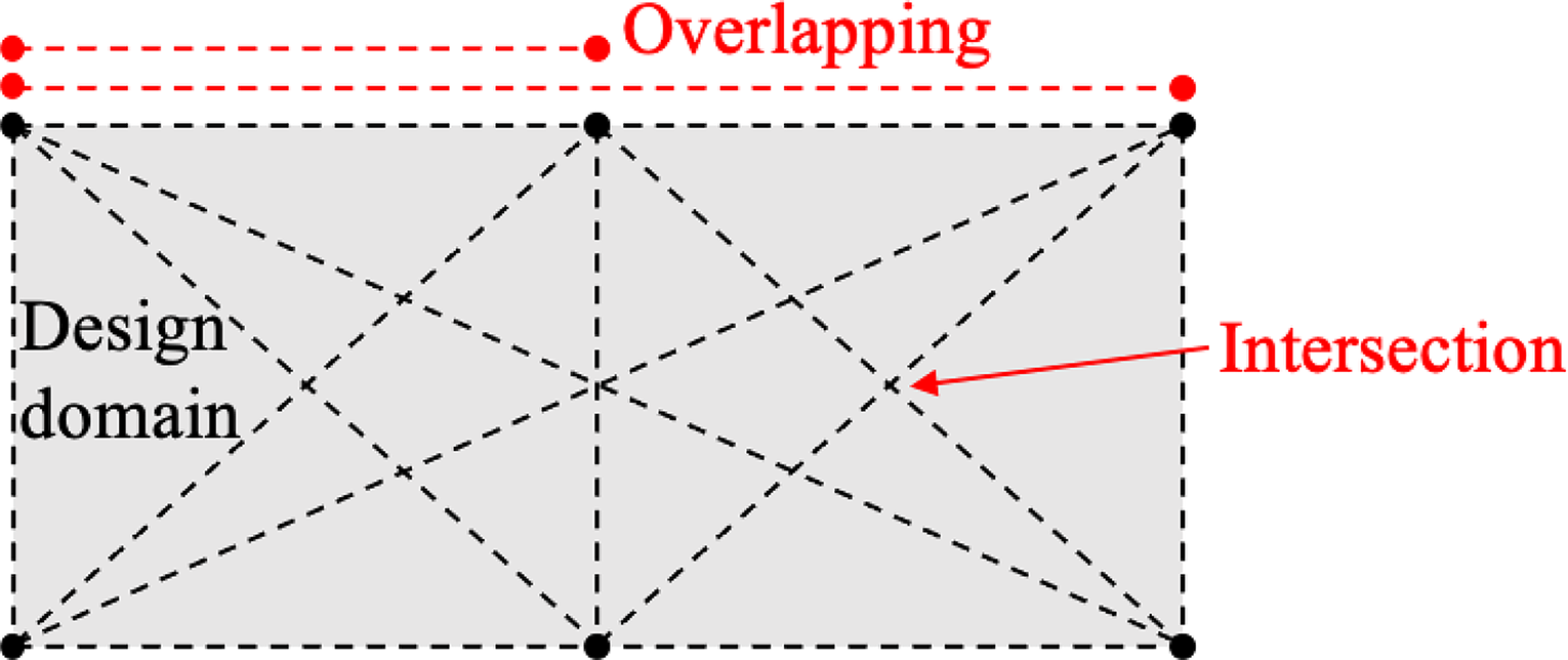
Illustration of a frame ground structure with member intersection and overlapping.
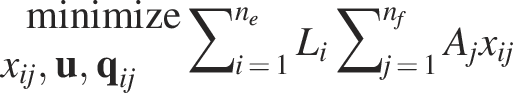
Topology optimization
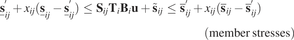
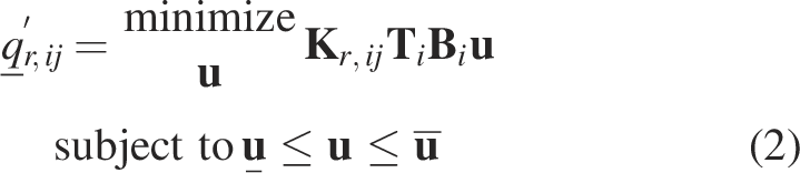
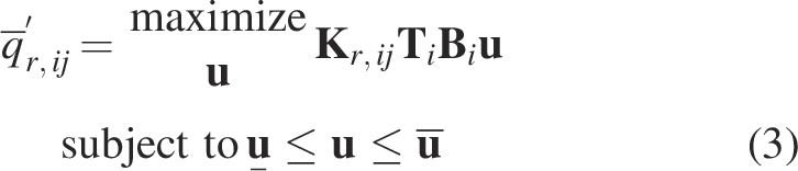
The topology optimization seeks the minimum weight of the structure with constraints on the nodal displacements and on the local member stresses by determining the existence of each potential member and finding the cross-sectional areas of the existing members. Considering the 3DCP’s material anisotropy, which exhibits the strongest performance in the printing direction, each existing member is preferred to be printed along its own length direction to maximize the member’s load-carrying capacity. This idea utilizes the anisotropy aptly and is similar to the additive manufacturing along the principal stress lines in the continuum setting.46–49
Consequently, the manufacturing constraint of the nozzle size requires the width of the member to be an integer multiple of the nozzle size, that is, the
In addition, the frame topology optimization problem can be formulated in a nested analysis and design (NAND) form or a simultaneous analysis and design (SAND) form.
50
The former uses


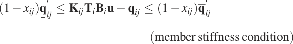

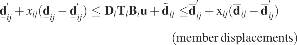

For
Simultaneous path optimization
To optimize the printing path simultaneously, the graph theory
44
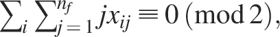
is employed. First, an efficient and high-quality printing requires the path to be globally continuous and to be covered only once. A Eulerian circuit fulfills this requirement as a “one-stroke” printing in one layer, and starting and ending at any identical position. For the subsequent layers, the printer simply necessitates a precise elevation of the nozzle, followed by a repetition of the previous path. In accordance with the graph theory, the existence of a Eulerian circuit is guaranteed whenever there is an even number (inclusive of zero) of filaments interconnecting all the distributed nodes. Therefore, this optimization constraint is expressed as
In terms of integer LP,
53
such a constraint can be modeled as a linear constraint with respect to
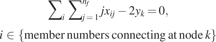

In this study, to narrow the optimization design space, the constraint is differently reformulated by introducing a binary variable,
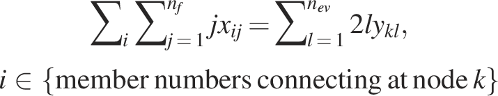


In practical computational scenarios, to further narrow the design space and enhance efficiency, it is advisable to truncate the right-hand side of the first equation above after the first term, which means that at most two filaments connect at the node. Subsequently, this truncation can be iteratively augmented by successively adding one term at a time (the maximum number of filaments at the node is increased by two), facilitating the exploration of a converged feasible solution. This process continues, if no feasible solution is found, until the condition
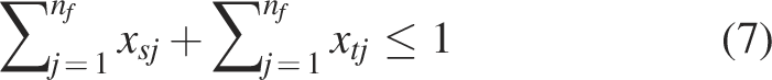
Second, there may exist necessary member intersection and overlapping in the initial ground structure, as illustrated in Figure 1, to not restrict the optimization design space. Consequently, the intersection and overlapping of members may be inherited in the Eulerian circuit-based frame. In practical printings, however, the intersection and overlapping phenomena should be avoided to ensure continuity and high quality. All the possible intersection and overlapping scenarios
54
are plotted in Figure 2. It can be observed that if two members are non-parallel and the intersection point is located inside at least one member (excluding the two endpoints), the two members intersect; if two members are a pair of colinear lines and share a common segment, the two members overlap. By associating each pair of potential members in the ground structure, the geometric relation between the two members can be determined mathematically through the member orientations and point coordinates. The algorithmic pseudocode is given in Appendix. If the
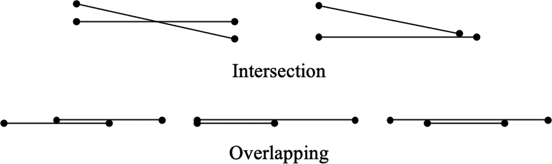
All possible scenarios for intersection and overlapping of two members.
This constraint assures that at least one of the two members does not exist and hence the intersection or overlapping is eliminated, and this constraint is a linear constraint with respect to
Moreover, in 3DCP, sharp turns in the printing path should be avoided to prevent defects such as underfilling and overfilling. A straightforward way to achieve this is by imposing an angular constraint between two potential members meeting at a common node. Such a constraint can also be conveniently enforced by Equation(7). Specifically, if the angle between the two members falls below a given threshold, the formulation ensures that at least one of them is excluded from the final layout, thereby precluding the occurrence of a sharp corner.
Last, since the external load is treated as equivalent nodal loads in the topology optimization, the members subjected to interior loads may be absent after the optimization, which will be shown later in a test problem. In this case, the members carrying the interior loads are mandatory, and hence the following path constraint can be provided:
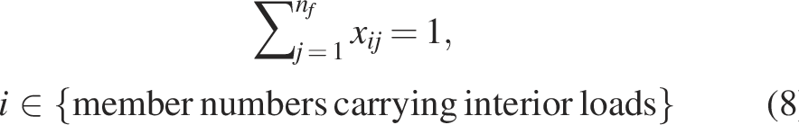
This constraint is also a linear constraint with respect to
In summary, Equations (1) and (6)–(8) define the simultaneous topology and path optimization problem for 3DCP. Owing to the requirement of structural topology optimization that the force transmission path must remain continuous and unbroken from the loading point to the supports, multiple disjoint paths are inherently excluded under the volume minimization objective. As will be demonstrated in the subsequent benchmark tests, this formulation consistently yields a single Eulerian circuit as the optimal solution. The overall optimization problem is formulated as an MILP, which is readily solvable. The “intlinprog” MILP solver, which predominantly relies on a branch-and-cut algorithm, in the general computing tool MATLAB 55 is employed subsequently to solve the test problems. And the solver is run on a laptop with a 1.6 GHz dual-core processor and 16 GB of memory.
Test Problems and Optimization Results
In this section, the simultaneous topology and path optimization formulation presented above is applied to five popular problems. The first problem is a simply supported beam subjected to a simple mid-span load. It is used to verify the optimization formulation because it can also be solved by complete enumeration. The second problem changes the single mid-span load into two concentrated loads, resulting in a four-point bending beam. The third problem changes the simply supported condition into a cantilever constraint. The optimal design of the cantilever location is to be investigated. The fourth problem is a simply supported beam subjected to a uniformly distributed load. In this case, due to the distributed load, not only the nodal displacements and stresses but also the displacements and stresses at the interior locations of the loaded members can be constrained. The first four problems analyze standard rectangular design domains, whereas the last one investigates a more complex L-shaped domain.
Simply supported beam subjected to a mid-span load
Figure 3a shows the design domain for a simply supported beam structure subjected to a mid-span load on the top surface. The span is
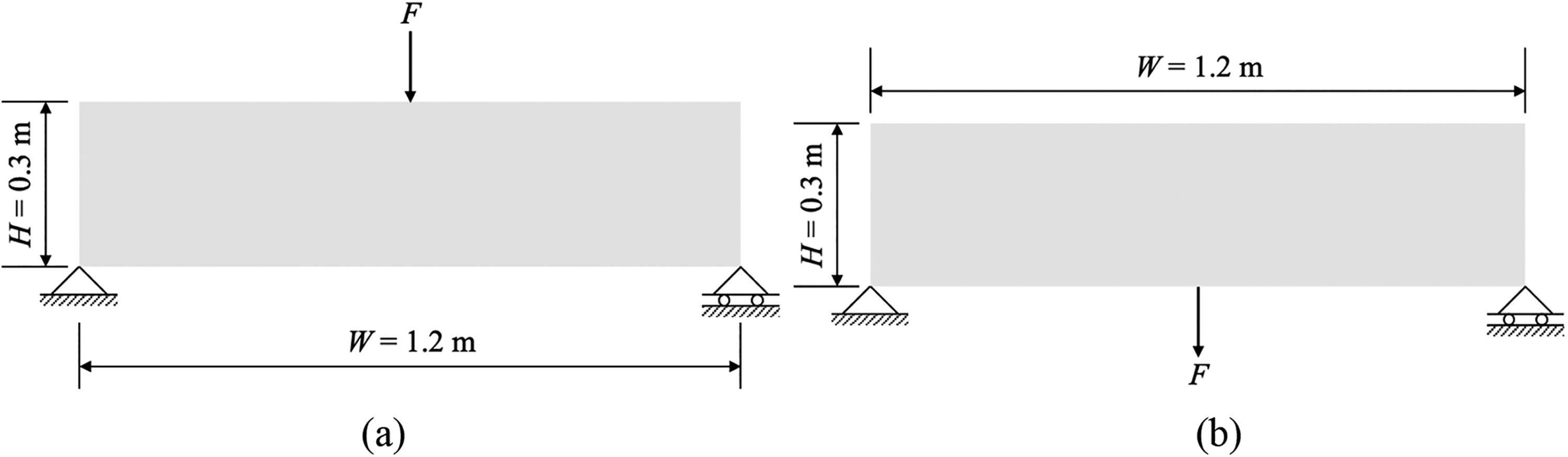
Design domains for a simply supported beam subjected to a mid-span load on:
Since members straightly connecting the loading point and the two supports are mechanically the most efficient ones to transfer the external load, it is sufficient to decompose the design domain by evenly distributed
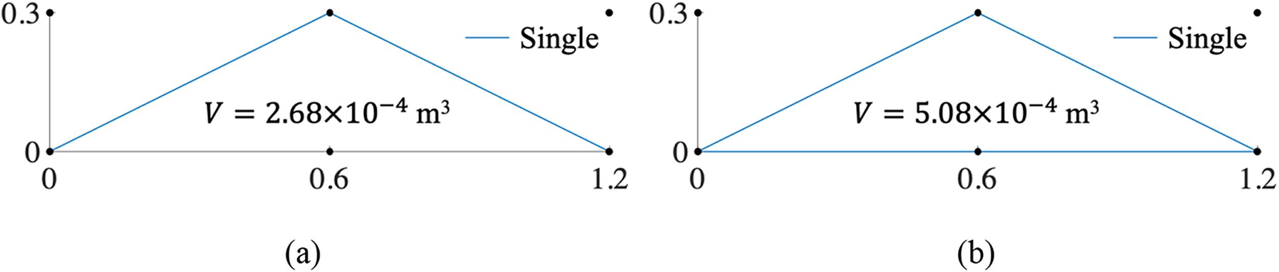
Optimal designs of the simply supported beam subjected to a top mid-span load
However, the path of the optimal design above is not an Eulerian circuit. Therefore, the path optimization constraints in Equations (6) and (7) are further supplied. The computational time was 1.5 s, and the optimal design obtained is shown in Figure 4b. A bottom single-filament member connecting the two supports is added to form an Eulerian circuit path, which is convenient for direct printing. Due to the stiffness increase of the whole structure, the vertical displacement at the loading point is reduced to
Since the maximum tensile stress above is about
Optimal designs of the simply supported beam subjected to a top mid-span load
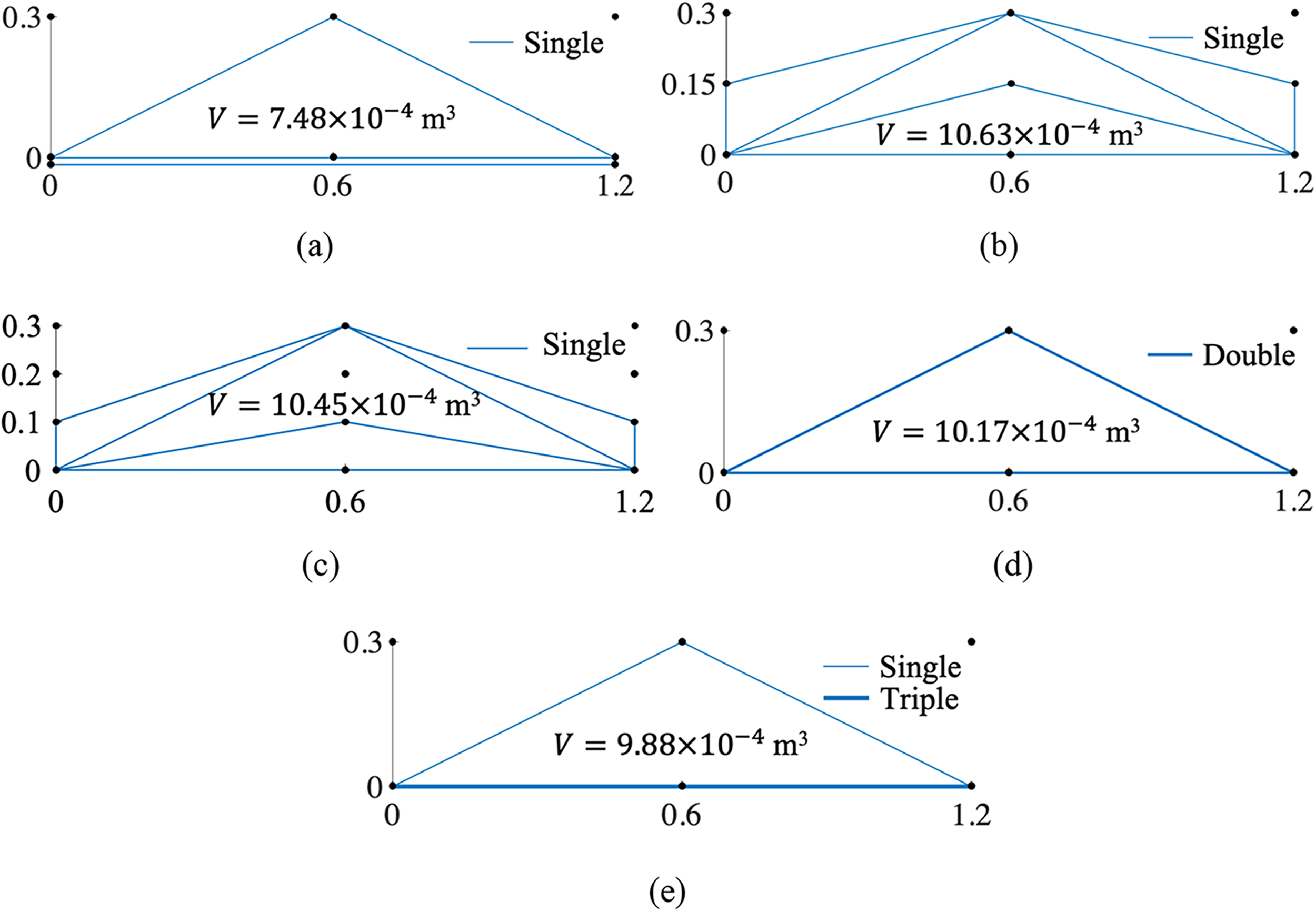
Similarly, the mid-span load may be applied on the bottom surface of the design domain, as shown in Figure 3b. When
For
Optimal designs of the simply supported beam subjected to a bottom mid-span load
As the top point moves downward, the bottom angles become progressively sharper. For instance, in the optimal design shown in Figure 6b, the angle is reduced to 9.5°. Assuming a minimum threshold of 10° is required to prevent underfilling or overfilling, this design violates the constraint. To address this, the angular constraint Equation 7 between the top inclined members and the bottom member was imposed. The resulting optimal design, shown in Figure 6e, successfully increases the angle to 18.4°, which is well above the required threshold.
Four-point bending beam
This problem mimics the four-point bending on a beam, as shown in Figure 7. Similar to the first problem,

Design domain for a four-point bending beam.
Optimal designs of the four-point bending beam:
It is further found that when the loads are slightly beyond 700 N, there is no feasible solution for
Cantilever beam
This problem is a cantilever beam subjected to an end load, as shown in Figure 9. When
Design domain for a cantilever beam.
Optimal designs of the cantilever beam:
Simply supported beam subjected to a uniformly distributed load
The fourth problem designs a simply supported beam structure subjected to a uniformly distributed load, as shown in Figure 11. Since the top-chord member is bent by the distributed load, besides the regular nodal displacements and stresses, specific constraints are imposed on the displacements and stresses at five equidistant locations, marked by “x” in Figure 11. To accommodate these five critical locations, two distinct strategies for node distribution are adopted. The first strategy involves positioning five uniformly spaced nodes horizontally, each directly corresponding to one of the marked locations. Alternatively, the second strategy utilizes three horizontally uniform nodes, necessitating additional constraints at the midpoints of the two halves of the top-chord member to ensure coverage of the designated locations.
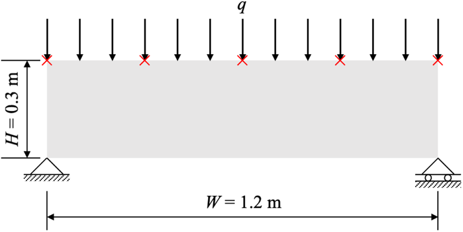
Design domain for a simply supported beam subjected to a uniformly distributed load.
When
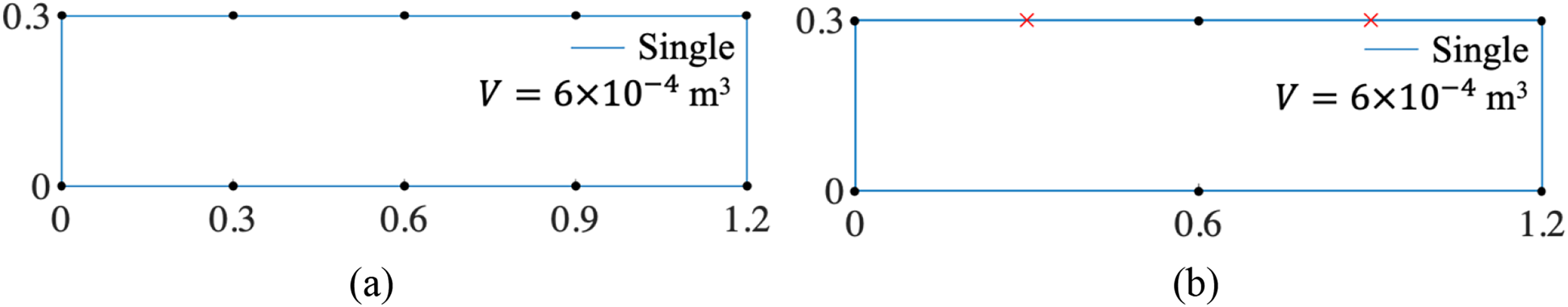
Optimal designs of the simply supported beam subjected to a uniformly distributed load
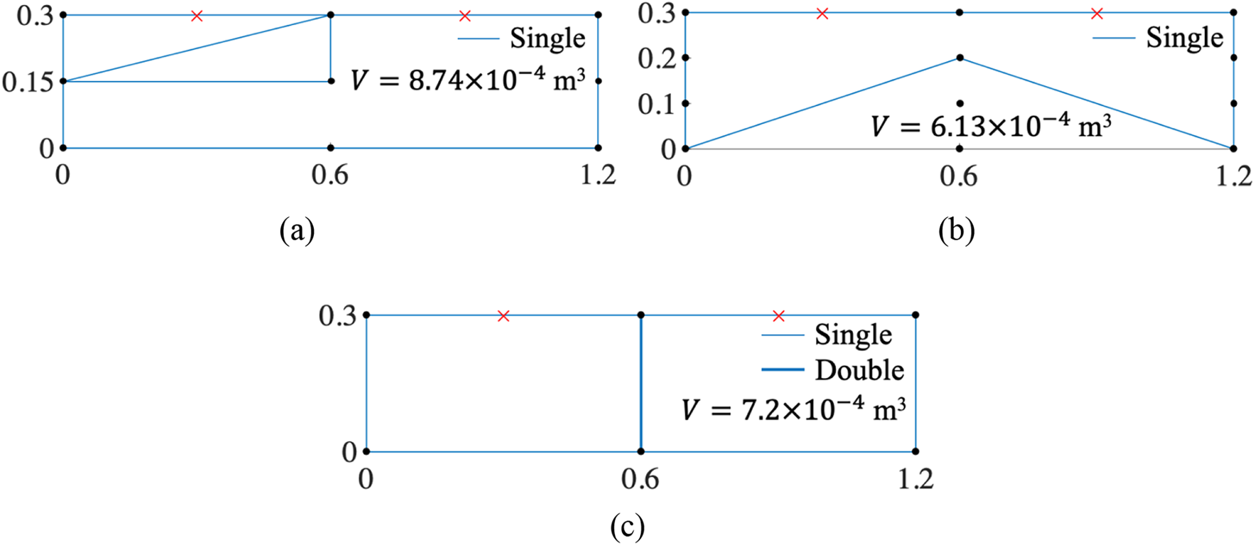
Optimal designs of the simply supported beam subjected to a uniformly distributed load
Figure 14a shows the optimal design for
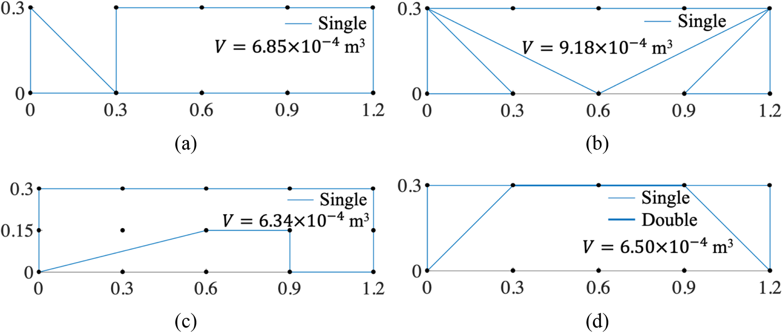
Optimal designs of the simply supported beam subjected to a uniformly distributed load
L-shaped bracket
The last problem evaluates a more complex design domain, specifically an L-shaped domain, as shown in Figure 15. Therefore, any member connecting two arbitrary nodes that lie partially or entirely outside this domain cannot be incorporated into the ground structure. Figure 16a and b plots the optimal designs for
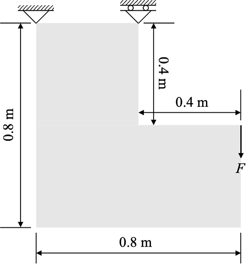
Design domain for an L-shaped bracket subjected to a point load.
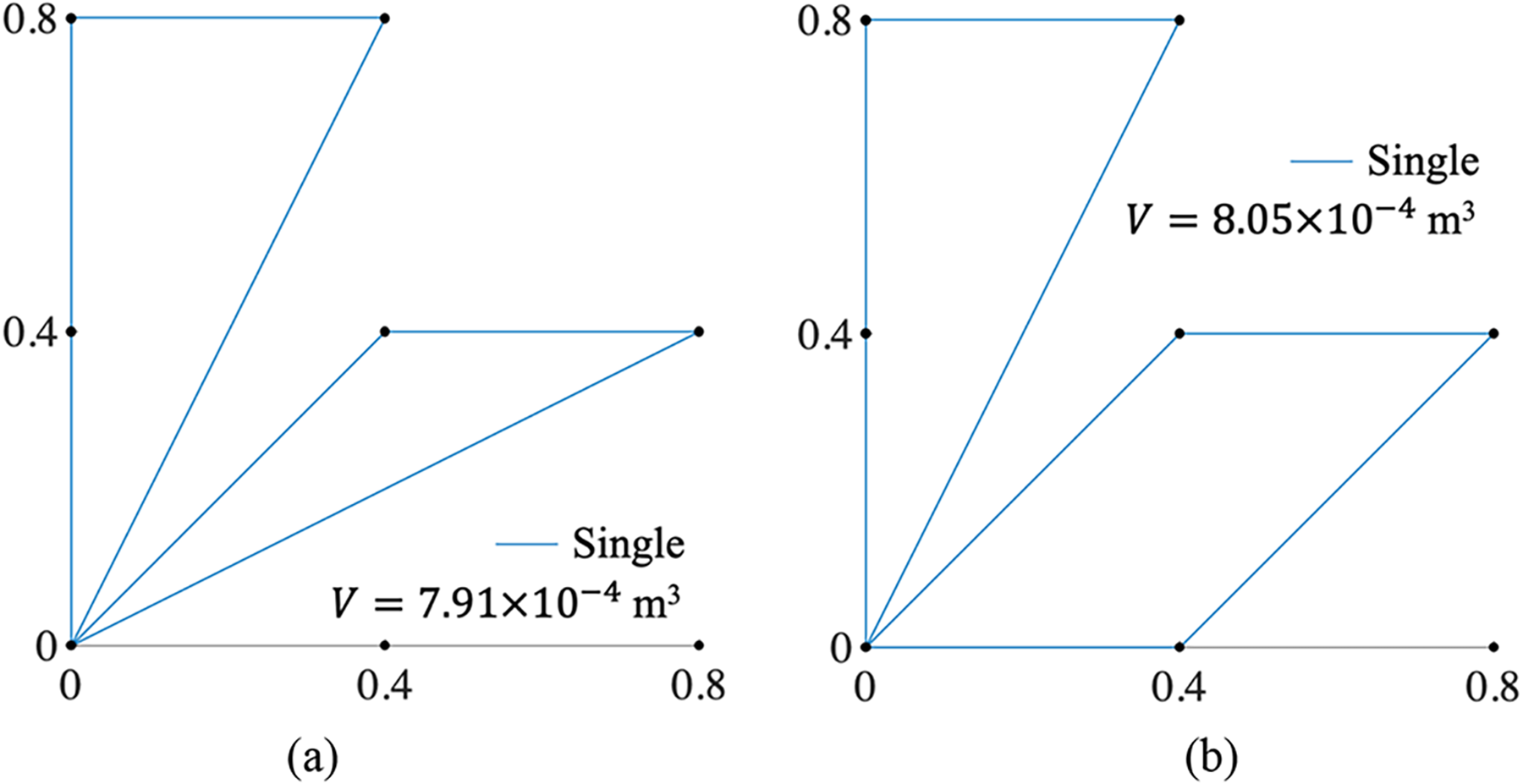
Optimal designs of the L-shaped bracket using
Figure 17a and b shows the optimal designs for

Optimal designs of the L-shaped bracket for
Conclusion
In this article, an innovative methodology for simultaneous topology and path optimization of 3DCP is introduced. This formulation, grounded in discrete frame structures, meticulously approximates the geometric intricacies of 3DCP, thereby enhancing the fidelity of the optimization process. Furthermore, the methodology astutely harnesses the mechanical anisotropy inherent in 3DCP, further optimizing the designs’ performance. The efficacy of this simultaneous optimization approach is rigorously demonstrated through a series of test cases. In these tests, the topology optimization component ensures that the resulting designs not only adhere to stringent structural displacement and stress constraints but also achieve minimal weight, optimizing material usage. Simultaneously, the path optimization guarantees global continuity, ensuring the design is traversed seamlessly, once and only once, without intersections or overlaps. In addition, it guarantees that the member widths are integer multiples of the nozzle size, facilitating seamless integration with the printing process. Consequently, the optimal designs generated by this methodology are poised for direct “one-stroke” printing, seamlessly bridging the gap between the optimized digital model and its physical realization. This integration not only streamlines the manufacturing process but also underscores the potential of advanced optimization techniques in revolutionizing the field of 3DCP. While this study optimizes single-layer structures with uniform cross-sections and in-plane loading, future work will extend this framework to three-dimensional applications. A key objective will be the incorporation of additional manufacturing constraints, such as maximum self-supporting overhang angles.
Authors’ Contributions
M.L. designed the article concept and methodology from the original idea and wrote the main article text. X.S. implemented the investigation and prepared the visualization. Z.C. acquired the funding and supervised the implementation. All authors reviewed the article.
Footnotes
Author Disclosure Statement
The authors declare that there are no conflicts of interest.
Funding Information
This study was funded by the National Key Research and Development Program of China (No. 2021YFF0500804).
Appendix
% In: ne – total number of potential members
% (x1, y1), (x2, y2) – coordinates of the two endpoints of the first member
% (x3, y3), (x4, y4) – coordinates of the two endpoints of the second member
% Out: CS – constraints
A = [y1-y2, x1-x2;
y3-y4, x3-x4]; % member slope matrix
B = [y1-y2, x2-x1, x2*y1-x1*y2;
y3-y4, x4-x3, x4*y3-x3*y4]; % coefficient matrix of two member lines
C = GE(B); % Gaussian elimination. C(1,3), C(2,3) – x and y values of intersection point
or
or
CS=
or
or
or
or
or
CS=
min(x1,x2)<x3<max(x1,x2) or min(x1,x2)<x4<max(x1,x2)
CS =
min(y1,y2)<y3<max(y1,y2) or min(y1,y2)<y4<max(y1,y2)
CS =
References
Supplementary Material
Please find the following supplemental material available below.
For Open Access articles published under a Creative Commons License, all supplemental material carries the same license as the article it is associated with.
For non-Open Access articles published, all supplemental material carries a non-exclusive license, and permission requests for re-use of supplemental material or any part of supplemental material shall be sent directly to the copyright owner as specified in the copyright notice associated with the article.