
Abstract
Introduction of RGB-D sensors is a revolutionary force that offers a portable, versatile and cost-effective solution of navigational assistance for the visually impaired. RGB-D sensors on the market such as Microsoft Kinect, Asus Xtion and Intel RealSense are mature products, but all have a minimum detecting distance of about 800 mm. This results in the loss of depth information and the omission of short-range obstacles, posing a significant risk on navigation. This paper puts forward a simple and effective approach to reduce the minimum range that enhances the reliability and safety of navigational assistance. Over-dense regions of IR speckles in two IR images are exploited as a stereo pair to generate short-range depth, as well as fusion of original depth image and RGB image to eliminate misjudgment. Besides, a seeded growing algorithm of obstacle detection with extended depth information is presented. Finally, the minimum range of Intel RealSense R200 is decreased by approximately 75%, from 650 mm to 165 mm. Experiment results show capacity of detecting obstacles from 165 mm to more than 5000 mm and improved performance of navigational assistance with expansion of detection range. The presented approach proves to be of qualified accuracy and speed for guiding the visually impaired.
Introduction
According to World Health Organization, 285 million people are estimated to be visually impaired and 39 million are blind in the whole world [30]. Visually impaired people have many difficulties in daily life. For instance, it poses challenges to visually impaired people to navigate through real-world obstacles because they can’t perceive their surroundings quite well. Modern solutions for navigational assistance have been making progressive improvement with the increased popularity of RGB-D sensors [12,22,33].
Ranging technique with RGB-D sensors such as Microsoft Kinect, Asus Xtion and Intel RealSense is a ubiquitous solution for navigational assistance with good portability, functional diversity and cost-effectiveness [14,23,26]. The sensor provides common interface with processors, and can be conveniently integrated in a wearable assistance device thanks to its small size and light weight. These RGB-D sensors capture a high-resolution RGB stream and a depth stream simultaneously at more than 30FPS. In addition, cost of such RGB-D sensors is less than 200USD. As shown in Fig. 1, Intel RealSense R200 is a typical example of RGB-D sensor. Based on the advantages above, these commercial RGB-D sensors are quite suitable for navigational assistance.
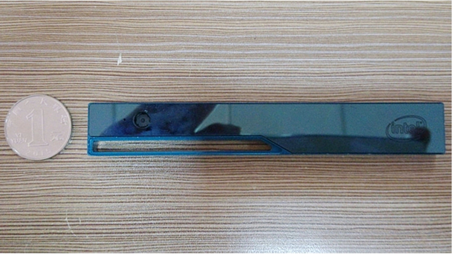
Intel RealSense R200. The sensor is small and light so it is a good option for navigational assistance from miniaturization perspective.

Image acquisition.
However, RGB-D sensors have some restrictions. One of the restrictions is a minimum detection range of about 800 mm. For Microsoft Kinect and Asus Xtion, the minimum range is 800 mm [2,12] while the minimum range is 650 mm for Intel RealSense R200. In the case of Intel RealSense R200, as shown in Fig. 2, if an object is within the detection range of 650 mm, there is a black hole in the depth image, and pixels in the black hole have no valid depth.
These RGB-D sensors consist of an IR laser projector which emits a structured infrared light pattern of IR laser speckles. A series of patterns is projected into scenes to encode real-world 3D points, and the IR sensor captures the speckles with a high sampling speed [18]. Size, shape and shift of a speckle change with the variation of the distance from the encoded object to the sensor. Speckles are measured in IR image to calculate disparity and then generate a depth image. However, short-range speckles are hard to identify due to over-exposure in IR image, which means the reflected structured light pattern is sufficiently bright to saturate the image sensor. As a result, these RGB-D sensors leave out short-range speckles which restricts the minimum range of detection, i.e. about 800 mm. In the case of navigational assistance, obstacles in close blind area cannot be easily detected and leave sight impaired people vulnerable in unknown, dynamic environments. Thereby, short-range depth imaging is desirable.
Recently, some methods have been proposed to tackle the problem of short-range detection of RGB-D sensors such as modification of optics of the sensor, deployment of multiple RGB-D sensors, combination with RGB information, 3D simultaneous localization and mapping (SLAM) based solution [13].
As for modification of optics, Nyko Zoom is a commercial wide-angle optical adaptor for Microsoft Kinect. Although it reduces both the minimum and maximum range, pronounced distortion in depth image is introduced. M. Draelos compensated the lens-introduced distortion through a depth calibration procedure and decreased the minimum range of Kinect by approximately 30% with Nyko Zoom [9]. However, the minimum detection range of RGB-D sensors is decided more by the over-exposure in IR image than the narrow horizontal field of view. As a result, this method still fails to give depth information of objects within 400 mm.
Fusion of multiple RGB-D sensors is implemented by some researchers in order to obtain a wilder field of view and decrease the minimum detection range. However, deploying multiple RGB-D sensors with overlapping views produces interference effects from overlapping speckles. F. Alhwarin used two IR images of each two Asus Xtions as a stereo pair to generate a depth map [2]. This method sidesteps the problem of the interference. With a baseline of 0.045 m, the minimum distance of Asus Xtion is decreased from 800 mm to 500 mm. However, this method is still unable to detect obstacles within half a meter. Y. Shröder used a spinning shutter to block the IR emitter on each Kinect in turn to mitigate the interference [28]. However, the framerate decreases a lot as laser speckles from each Kinect cannot access the scene all the time. Moreover, a spinning shutter is too heavy to be integrated in a navigational assistance system. A. Maimone applied a small vibration with a simple motor to a subset of Kinects to alleviate the interference [20]. However, this method contributes a side-effect: blurring in color images. Moreover, movement of sensors would pose great challenges for detection algorithms to give accurate locations of obstacles in navigational assistance.
Combining RGB image with either depth image or IR image is adopted by some researchers to cope with the range limitation. In order to provide the visually impaired with obstacle-free paths, A. Aladrén firstly detects ground with RANdom SAmple Consensus (RANSAC), then expends the depth based ground segmentation with RGB image [1,10,25]. This method is quite suitable to expand detection result to longer range, but not robust enough to get short-range information. Moreover, the algorithm runs at a speed of approximately 0.3 frames/s, which fails to provide real-time implementation. W. Chiu complemented the depth image of Microsoft Kinect by a cross-modal stereo matching between RGB and IR camera [6,7]. The minimum range is reduced, since this method could obtain wide overlapping field due to short baseline of IR camera and RGB camera of the RGB-D sensor. Nonetheless, short-range objects tend to be texture-less and change in IR image with emitting speckles, making robust depth estimation extremely difficult. As a result, cross-modal stereo matching is not framed to tackle the minimum range problem.
In terms of 3D simultaneous localization and mapping (SLAM), the based solution could build a vicinity map. Therefore, instead of original depth image, short-range information is acquired through the vicinity map. Y.H. Lee adopted a metric-topological SLAM approach to provide the visually impaired with 3D traversability on the map [17,24]. This method achieves processing speed of 12–15 Hz and helps the visually impaired improve the mobility performance. Although SLAM based navigation can be real-time through optimization, it will lose connection with the vicinity map if there are not enough features in the scene. Especially, it is notable that low textured area affects the visual odometry performance.
Though many related work have addressed both problems, they do not decrease the minimum range to a large extent or cause intolerable side effects in navigational assistance. In this paper we present a novel approach to make full use of over-dense speckle regions in IR image. A commercial RGB-D sensor Intel RealSense R200 is implemented which consists of two IR sensors. Over-dense regions of IR speckles are extracted, which secludes short-range objects. And these regions in two IR images are exploited as a stereo pair. Since over-dense speckle regions tend to be poorly-textured, a stereo algorithm based on local correspondences is adopted to acquire an edge disparity image [11,27,29]. This allows efficient exploitation of over-dense regions and real-time processing. Thereby, depth of short-range obstacle can be retrieved from the corresponding edge disparity pixels. However, objects sometimes will be mistakenly recognized as short-range obstacles. In this case, we do not choose to use IR images from the sensor, but we fuse original depth image and RGB image to eliminate some misjudgment such as luminous objects in the distance. After short-range depth information complemented, a seeded region depth growing algorithm is presented to detect obstacles.
The main advantages of our approach can be summarized as follows:
It provides a novel solution to decrease the minimum range of RGB-D sensor to a large extent.
The safety and reliability of navigational assistance for vision impaired people with RGB-D sensor can be improved dramatically.
Over-dense speckle regions are fully considered by RGB-D sensors based on structured light.
The approach is simple and computationally efficient, providing real-time implementation.
The seeded region depth growing algorithm detects obstacles with qualified robustness and speed.
The paper is organized as follows. In Section 2, the approach is elaborated in detail. In Section 3, substantial experiments demonstrate the approach’s effectiveness in terms of decreasing minimum range of RGB-D sensors and improving performance of navigational assistance. In Section 4, relevant conclusions are drawn and future work is expected.
In this section, the approach of short-range depth acquirement and obstacle detection algorithm is elaborated in detail. The approach is described in terms of sensor attribute, depth generation and obstacle detection.
Sensor attribute
A RGB-D sensor Intel RealSense R200 is used in our case to capture scenes. As shown in Fig. 3, Intel RealSense R200 consists of a RGB camera with a resolution of 1920 × 1080 pixels and two IR cameras with a resolution of 628 × 468 pixels. The IR cameras are set apart with a baseline of 70 mm, calibrated. Original depth information from Intel RealSense R200 can be divided into three ranges:
0–650 mm: There is no valid depth, and we attempt to acquire depth in this range.
650 mm–about 2700 mm: Laser speckles are well recognized, and depth is measured through speckle changes. The max range, i.e. 2700 mm, is floating with laser power and ambient light.
More than 2700 mm: Depth is measured through stereo matching.
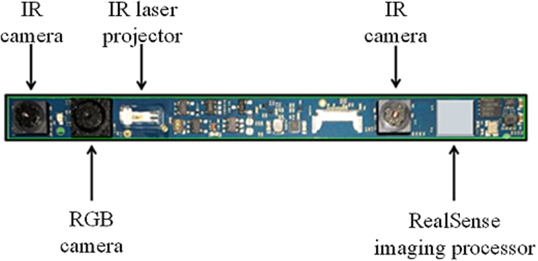
Intel RealSense R200 consists of an imaging processor, a IR laser projector, a RGB camera and two IR cameras.
Before short-range depth generation, an offline calibration process is performed on two IR cameras and the RGB camera of Intel RealSense R200. The camera calibration technique comprises intrinsic calibration, stereo calibration and stereo rectification [32]. The calibration parameters of Intel RealSense R200 are shown in Table 1 and these parameters are used for depth generation and information fusion. Stereo rectification is performed on raw IR images to align scanlines to simplify disparity calculation. As a result, the task of extracting depth image from left IR image and right IR image turns into estimation of disparity map [4].
Calibration parameters of Intel RealSense R200
Calibration parameters of Intel RealSense R200

The disparity generation pipeline.
As shown in Fig. 4, the disparity computation procedure comprises capturing images, extracting over-dense speckle regions, eliminating misjudgment and block matching. Firstly, the RGB-D sensor captures a RGB image, a depth image and two IR images. Short-range objects are encoded with dense speckles, which results in over-exposure in IR images. Secondly, we aim to extract over-dense speckle regions in IR images. Since the speckles are hard to recognize, the RGB-D sensor can’t calculate depth at these pixels. Rather than ignore the over-dense regions, we take full advantage of these regions which lacks textures. A typical edge processing is employed on two IR images. We can easily extract these regions in edge image since over-dense regions are edge-less. In our case, the output is binary images given by the Canny edge detector. However, there are other regions without edges too, which inevitably cause some misjudgment. As a result, elimination of misjudgment is required to mitigate interference of special objects. For instance, shinning objects in the distance appear to be over-dense speckle regions in IR images. In this work, two misidentification elimination rules are determined:
In the original depth image, if a pixel has a valid depth, this pixel is not within minimum range.
In the RGB image, if a pixel has an abnormally high brightness, this pixel is regarded as misidentification.
After implementation of the rules, over-dense regions correspond to short-range objects. Furthermore, over-dense speckle regions in two rectified IR images are exploited as an IR stereo pair for disparity calculation. Since over-dense regions are less of textures, a blocking matching algorithm based on local correspondence is applied, to determine edge disparities of these regions, which indicates the difference in locating corresponding pixels in two IR images [15]. Generally, block matching requires to define a matching score and an aggregation window. In this work, a common dissimilarity score is utilized to measure the sum of absolute intensity differences (SAD) [3,27]. SAD is defined as Eq. (1):
The block matching algorithm has four steps:
Construct an aggregation window. The block window is similar to a convolution kernel in use.
Use the window to cover a block of left IR image, and obtain sum of pixel intensities in the window.
Use the window to cover a block of right IR image with shifting horizontal position of the window, sums of pixel intensities and SAD of different positions are obtained.
After calculating SAD of different positions, select the best match using the winner takes all (WTA) algorithm. The block with the lowest matching cost SAD is searched for and its position is chosen as the pixel value for the disparity map.
Traversing the image within disparity search range, we obtain a rough disparity image. Then, three assumptions are combined to renovate the disparity image:
Disparity component assumption: assume the image consists of a number of connected sets of pixels with same disparity, which coincides with our condition, as disparities of an obstacle won’t differ vastly [5,8].
Disparity uniqueness assumption: assume ratio of lowest SAD to second lowest SAD is smaller than a threshold, which rejects some mismatching pixels.
Texture adequacy assumption: assume sum of pixel gradients in the window exceeds a threshold, which only retains disparities of edge pixels of an obstacle.
The disparity matching algorithm is computationally efficient for edge disparity estimation. Thus, short-range objects’ edge disparity is acquired with proper matching search range along the aligned scanline. In our case, since two IR cameras are set apart with a baseline T of 70 mm and focal length f about 580 pixels, the search range of disparity Δ is set as 60 pixels to 250 pixels. Accordingly, this method matches the edges of objects within 165 mm–650 mm as Eq. (2) computed.
Depth calculation and fusion
The edge disparity image corresponds to IR stereo depth image. For each non-zero disparity, depth of the pixel is calculated through Eq. (2). Thereupon, a IR stereo depth image is obtained, which represents depth of short-range objects. Then, we perform fusion of short-range depth information with original information:
Fusion of short-range depth image and original depth image.
Fusion of short-range depth image with IR image and RGB image.
The fusion of depth is calculated by replacing value of invalid depth pixels with corresponding one from the IR stereo depth, as shown in Eq. (3). As for each pixel, the depth equals original depth, if the Bool of the pixel equals to 1, which means the original depth of the pixel is valid. Otherwise, the depth equals IR stereo depth. The original RGB-D depth and short-range IR stereo depth are fused into a synthetic depth image, as shown in Fig. 5.
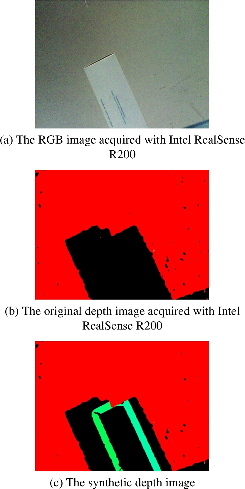
The fusion of the original depth image and short-range IR stereo depth image. The edge depth of the short-range objects is added in the original RGB-D depth image.
Next, we fuse IR stereo depth image with IR image and RGB image. Since the IR stereo image corresponds to one IR image, an image registration is performed with the RGB image and the IR image. Assume
Assume
In Eq. (4), R is the rotation matrix and T is the translation matrix. As shown in Eq. (6), it can acquire the corresponding coordinate in the RGB image by using the intrinsic matrix
In this work, we use the average edge depth of a short-range object and relevant calibration parameters to project to the RGB image, and replace the minimum bounding rectangle of the object in the IR image with the RGB information. As shown in Fig. 6, we mark the average depth of the object at the center of the rectangle.
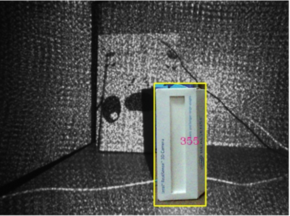
The fusion of the IR stereo and the RGB image. The average depth of the object is marked in scale of millimeter.
A seeded region growing algorithm is presented to perform obstacle detection with fused depth information.
The de-noising and hole-filling is essential before conducting obstacle detection, since a lot of noise and miss-match pixels exist in the depth image. In this work, we use an adaptive cross-trilateral depth map filtering algorithm [19,21,31] to refine the depth image.
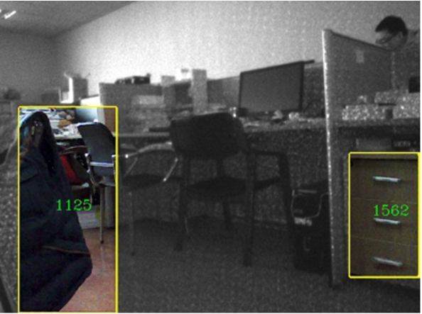
The obstacle detection with the seeded region growing algorithm. In the IR image, obstacles in the minimum bounding rectangle are replaced with the RGB information, which are projected with average depth. The depth value in a scale of millimeter is marked in the image.
Seeds in the obstacles detection are selected between the edges of the depth image. By analyzing the depth divergence, sets of pixels of same growing result are classified as obstacles [16]. Then, we select several evenly distributed rows in the depth image. In each row, seeds are selected at the middle point of two edge pixels and starts to extend itself until one of following four conditions is satisfied:
The growing pixel meets the edge pixel.
The growing pixel belongs to any other regions.
The growing pixel is visited during the growing course of the current seed.
The depth difference of two adjacent pixels exceeds the growing threshold.
After the growing process, several regions where the seeds grew appear on the image. Not all of the regions belong to the obstacles and an entire obstacle may be grown to several parts. Thus, several measures are conducted to exclude or combine regions as mentioned below:
Regions which have few pixels are excluded.
Adjacent regions which have similar height are combined.
Because the boundaries of the obstacles always vary sharply, regions whose boundaries are mostly continuous are excluded.
The minimum bounding rectangle of the obstacle is replaced with the RGB information, similar to the process in the fusion of short-range depth and RGB image. As shown in Fig. 7, the projection is performed with the average depth of the object and the depth is marked at the center of the rectangle.
The presented approach has been evaluated with several experiments including ranging accuracy, obstacle detection as well as a contrast test.
Accuracy test is performed to analyze ranging accuracy of three ranges and study whether it meets the requirement for accuracy of navigational assistance. Obstacle detection is performed to study the effectiveness of detecting various obstacles and the running time of the algorithm. The contrast test is to check whether it helps navigational assistance with minimum range decreased by comparing performance with or without short-range information.
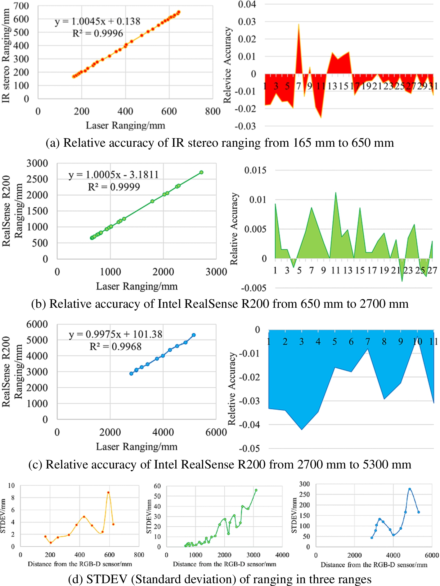
Accuracy test result on three ranges of Intel RealSense R200.
From Section 2.1, we know depth information is divided into three ranges, in which the short-range is realized in this paper. Owing to this, the accuracy test is performed separately in terms of three ranges and the results are shown in Fig. 8. The relative accuracy is calculated in comparison with the result of the laser ranging, which is set as truth-value. In terms of the range of IR stereo ranging from 165 mm to 650 mm, the relative accuracy is less than 2.5%, and
Generally, the accuracy of structure light ranging is better than that of the stereo matching ranging as the former one equivalently measures known textures while the latter one measures real-world textures which tend to create more errors. The result reinforced the speculation and that’s why the relative accuracy of the second range is the lowest. Besides, ranging standard deviation increases as distance increases, and the standard deviation of the first range is lowest. From Eq. (2), we deduce Eqs. (7), (8), (9). As the distance of the object from the sensor, i.e. d, increases, disparity Δ decreases which leads to the increase of
Overall, the relative ranging accuracy of the range which ranges from 650 mm to 2700 mm is the lowest, and the standard deviation of the range which ranges from 165 mm to 650 mm is the lowest. To briefly summarize, the ranging error of the range within 3 m is lower than 3.5 cm. Apparently, the accuracy satisfies the requirement of navigational assistance for the visually impaired.
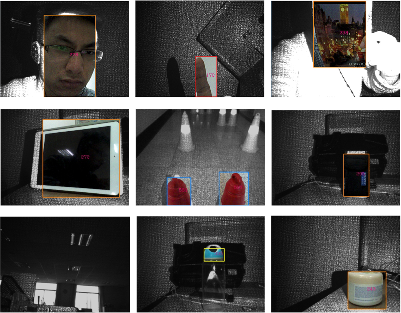
Short-range obstacle detection: the background is the IR image, and the RGB information of the obstacle is projected using average depth of the object, and the depth in a scale of millimeter is marked in the image. Obstacles of different materials, textures and distances can be correctly detected, and shiny objects in the distance would not be wrongly detected.
With short-range information complemented, the seeded region growing algorithm is evaluated for various obstacles of different materials, textures and distances.
Short-range obstacles are detected with IR stereo depth. Shown in Fig. 9, we demonstrate the capability of detecting different obstacles including human face, finger, postcard, display screen, matte objects, texture-less objects, curved surface objects. Besides, artificial light source such as fluorescent lamp in the distance and sunlight outside of window are not detected as short-range object any more. However, transparent objects such as glasses would be undetected because laser speckles would transmit through glasses instead of forming an over-exposed region in IR image.
As far as the maximum range is concerned, we found out maximum range of IR stereo would change through adjusting gain of IR camera. As shown in Fig. 10, the maximum range of the IR stereo to IR camera gain shows a logarithmic increase (

Relationship between maximum range stereo and IR camera gain.
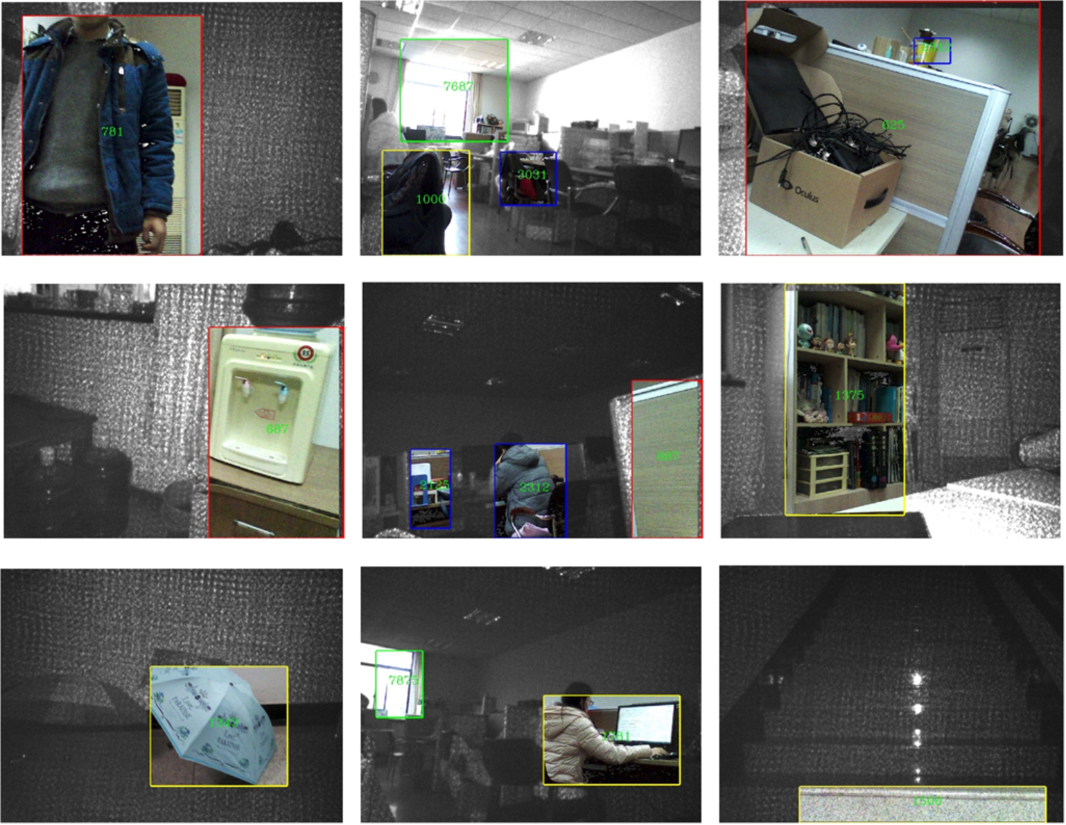
Obstacle detection from more than minimum range of the sensor: the background is the IR image, and the RGB information of the obstacle is projected using average depth of the object, and the depth in a scale of millimeter is marked in the image. Obstacles of different shapes and locations can be correctly detected.
Meanwhile, if the distance between an obstacle and the sensor is more than 650 mm, obstacles are detected with original depth information. Shown in Fig. 11, obstacles of different shapes and locations are correctly detected including human body, chair, window, cabinet, stair and umbrella. However, this algorithm still fails on transparent objects.
The running time of the individual parts of the algorithm for a single frame on Microsoft Surface Pro 3 with a 1.90 GHz CPU is shown in Table 2. The total time of a single frame is 161 ms, which makes obstacle be detected at about 6FPS feasible. Moreover, the development environment is Microsoft Visual Studio 2012 and OpenCV library is employed.
Together, obstacle detection results show the capacity of detecting obstacles ranging from 165 mm to more than 5000 mm at 6FPS. We provide empirical evidences concerning the drastic improvement of the detection range of the RGB-D sensor and the qualified robustness and speed of obstacle detection.
The running time
An experiment is carried out to check whether short-range depth information could influence the performance of navigational assistance. In this work, a contrary test is designed to compare its performance under two conditions: with or without short-range information for obstacle detection.
As shown in Fig. 12, the experiment device in a portable format includes: Intel RealSense R200, a 3D printed frame to hold the sensor, a vibrating belt and the processor Microsoft Surface Pro 3. It can be seen this device is light and easy to wear. The vibrating belt is adopted as feedback device to indicate obstacle distance and direction. The belt is consisted of 7 haptic actuators and each actuator corresponds to obstacles in each direction. We transfer information of closest 3 obstacles to the belt. If the number of obstacles is less than 3, information of all obstacles are transferred to the belt. The vibrating intensity contains 4 levels: 0–3. The closer the obstacle, the higher the vibrating intensity grows.

Experiment device of navigational assistance: the RGB-D sensor, a processor and a vibrating belt.
In this experiment, participants were asked to traverse through obstacles avoiding collisions with obstacles or walls. As shown in Fig. 13, nine different obstacle arrangement were generated by arranging the position of each obstacle differently. A set of identical traffic road cones were used as obstacles. Eight visually impaired volunteers including three suffering from total blindness participated in the test. Before experiment, they have never tried this device so we gave them a simple introduction of working pattern of the system and signals from the vibrating belt. Each one of them first completed the task of obstacle avoidance for all arrangements in a random order with short-range depth information complemented. After that, they were asked to complete without short-range depth complemented, which means the obstacle detection algorithm runs with only original RGB-D depth image from the sensor.
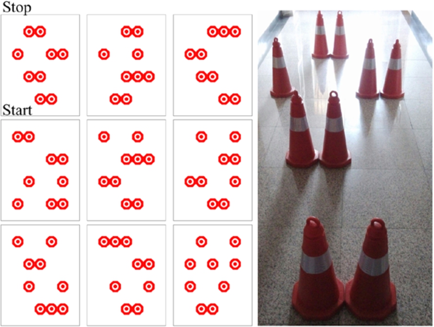
Schematics of all nine obstacle arrangements and a photo of one arrangement.
All participants were able to complete the experiment with the wearable experiment device and a blinder. Number of total collisions in each trial are shown in Fig. 14. Collisions include collision with obstacles and walls. The timer starts when a participant is sent to the start region and stops when the participant arrives the stop region. When obstacle algorithm runs with short-range depth information and original depth information, they collide with obstacles and walls 63 times altogether. When obstacle algorithm runs with only original depth from the sensor, they collide 118 times altogether. The number of collisions with minimum range decreased is 46.6% less than that without minimum range decreased. Besides, the average time of each trial with short-range depth information is 41 s, while the average time is 76 s without short-range depth information. This is a big improvement of navigational assistance performance since other experimental conditions are controlled to be the same. It is convinced that the presented approach which decreases the minimum range of detection could enhance the reliability and safety of navigational assistance. Besides, we found out that as trial times increase, the average total time of a participant to complete a single obstacle avoidance traverse decreases, since the participants are more and more acquainted with the device. We can rule out the possibility that decrease of the number of collisions is due to variation of familiarity. Because the test was performed with minimum range decreased first, it would help improve rather than weaken the performance of navigational assistance without short-range information if they are more familiar with the device afterwards.
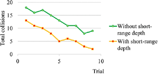
Number of total collisions in two conditions. The number of total collisions of eight participants is 63 with short-range depth while the number is 118 without short-range depth.
RGB-D sensor is a great choice for navigational assistance to capture information from real-world scenes. However, they all have a minimum range of about 800 mm, because within minimum range, laser speckles are hard to recognize due to over-exposure in IR image. As a result, the RGB-D sensors fail to generate depth within minimum range. In this paper, we present a novel method to make full use of over-dense speckle regions in IR image for stereo matching and generate short-range depth. A RGB-D sensor Intel RealSense R200 is used, with which the minimum range is decreased by approximately 75%, namely from 650 mm to 165 mm. The approach is tested and gives out a ranging accuracy of 2.5%, a processing speed of 6FPS on Microsoft Surface Pro 3, which satisfies the requirement for accuracy and speed of navigational assistance for visually impaired individuals. With seeded region growing algorithm, we show the capability of correctly detecting obstacles ranging from 165 mm to more than 5000 m, which enlarges original detecting range of the sensor drastically. The algorithm is robust in terms of different obstacles and is computationally efficient for real-time implementation. Together, a contrary navigational assistance test is performed, showing improved performance with short-range depth information complemented. It is demonstrated that the presented approach can effectively decrease the minimum range of a RGB-D sensor and enhance the reliability of navigational assistance.
In the future, we aim to incessantly enhance our navigation assistance approach for the visually impaired. Specifically, we look forward to including more sophisticated refine schemes for short-range imaging and further investigating obstacle detection schemes such as improving the performance on transparent objects.