
Abstract
Background:
Although cervical total disc replacement (TDR) is becoming popular, there are no finite analysis (FEA) studies involving a model of the full spine cervical (C1–C7) and determination of the influence of materials assigned to different parts of a specified TDR design on biomechanics of the model when TDR implantation is simulated.
Objective:
To determine the influence of assigned material combination, for a given cervical TDR design, on the kinematics of a model of the full cervical spine.
Methods:
A three-dimensional solid model of the full cervical spine was constructed, a finite element mesh was obtained (INT Model), after which FEA was used to determine range of motion (ROM) at each of the intersegmental positions under three clinically-relevant loadings. INT model was then modified by simulated implantation of a notional endplates-and-mobile insert TDR design, at C5–C6 (TDR Model), and six clinically-relevant applied loadings were applied. Four variants of TDR Model were used, the difference between them being in the materials assigned to the endplates and the mobile insert. Under each of the loadings, principal motions at each of the intersegmental positions were determined and compared to counterpart motions when INT Model was used.
Results:
Comparison of ROM results of INT Model with relevant experimental results reported in the literature showed that the model was validated. With TDR Model,
Conclusion:
In a simulated implantation of a notional endplates-and-mobile-insert TDR design in a model of the full cervical spine, material combination assigned to the parts of the design exerts a marked influence on the kinematics of the model.
Introduction
There are myriad symptomatic presentations of degenerative disc disease (DDD), such as herniation of the nucleus pulposus, discogenic pain, loss of disc height, loss of segmental mobility, development of osteophytes along the spine, myelopathy, radiculopathy, myelo-radiculopathy, and traumatic instability at one or more levels [1]. Treatment of these symptoms may be grouped into two categories: a conservative method, such as physical therapy [2] (when the pain arising from the symptoms is mild) and surgical intervention (when the accompanying pain is severe, or persistent; or is unresponsive to conservative treatment) [3,4]. Although, for a long time, the consensus was that the gold standard surgical intervention is anterior cervical discectomy followed by fusion (ACDF), another surgical intervention method, namely, total disc arthroplasty (that is, implantation of a total disc replacement) (TDR)), is becoming popular [5–10]. This trend reflects a growing appreciation of the advantages of TDR, such as preservation of motion at the operated level, lower rate of adjacent-level degeneration compared to ACDF, and lower reoperation rate compared to ACDF [1,11].
The literature on finite element analysis (FEA) of models of the cervical spine that include a simulated TDR has two key features. The first is that three types of study have been reported. These are 1) comparison of biomechanical responses between an intact model of a specific cervical spine section and a model in which the intact model is altered by insertion of a TDR design at a given level [12–17]; 2) investigation of the influence of the position of the center of rotation of a given TDR design on biomechanical parameters of a model of a section of the spine [18]; and 3) determination of the influence of TDR design on various biomechanical parameters of a model of a spine section [19–22]. The second key feature is that a full cervical spine model has been used in only one study [17]. To the best of our knowledge, there are no FEA studies on the influence of material combination assigned to different parts of a given TDR design on biomechanical parameters of a full cervical spine model.
The purpose of the present FEA study was to investigate the influence of the materials assigned to different parts of a TDR design (a notional endplates-and-mobile insert type) on biomechanical responses of a full cervical spine model (C1–C7). The TDR was simulated to be implanted at the C5–C6 level, as is the case in many clinical series [23] and each of the applied loadings used is comparable to that experienced at the cervical spine during some activities of daily living [24]. The biomechanical responses determined were the principal motions at each of the intersegmental positions.
Materials and methods
Study design
Five three-dimensional (3D) solid models of C1–C7 were constructed: the first was of an intact, healthy spine and the others were modifications of this spine to simulate implantation of four variants of a notional TDR design at C5–C6. Each of these models was subjected to an assortment of clinically-relevant loadings and the FEA was performed.
Model of intact, healthy spine
The solid model was built by 1) downloading digitized quantitative axial computed tomography scans/images of the bony parts, namely, vertebral bodies, posterior elements (comprising the transverse processes, pedicles, laminae, spinous processes, and facet joints), and the endplates, of the cervical spine of a male cadaver, from a public database (Visible Human Project® dataset (National Library of Medicine, Bethesda, MD, USA)); 2) exporting these images to a 3D scanning software package (Mimics® Version 8.1; Materialise, Inc., Leuven, Belgium) and to a 3D medical image processing and editing software package (RapidForm® Version 2006; INUS Technology, Inc., Seoul. South Korea); and, then, 3) exporting to a computer-aided drawing software package (ProEngineer® Wildfire 5.0; Parametric Technology Corporation, Needham, MA, USA). Each of the intervertebral discs (with the annulus fibrosus and the nucleus pulposus occupying 60% and 40% of the total volume, respectively [25]) and each of the ligaments were built separately. Then, the three sub-models (bony parts, discs, and ligaments) were combined to produce the final solid/geometrical model (Fig. 1(A)).
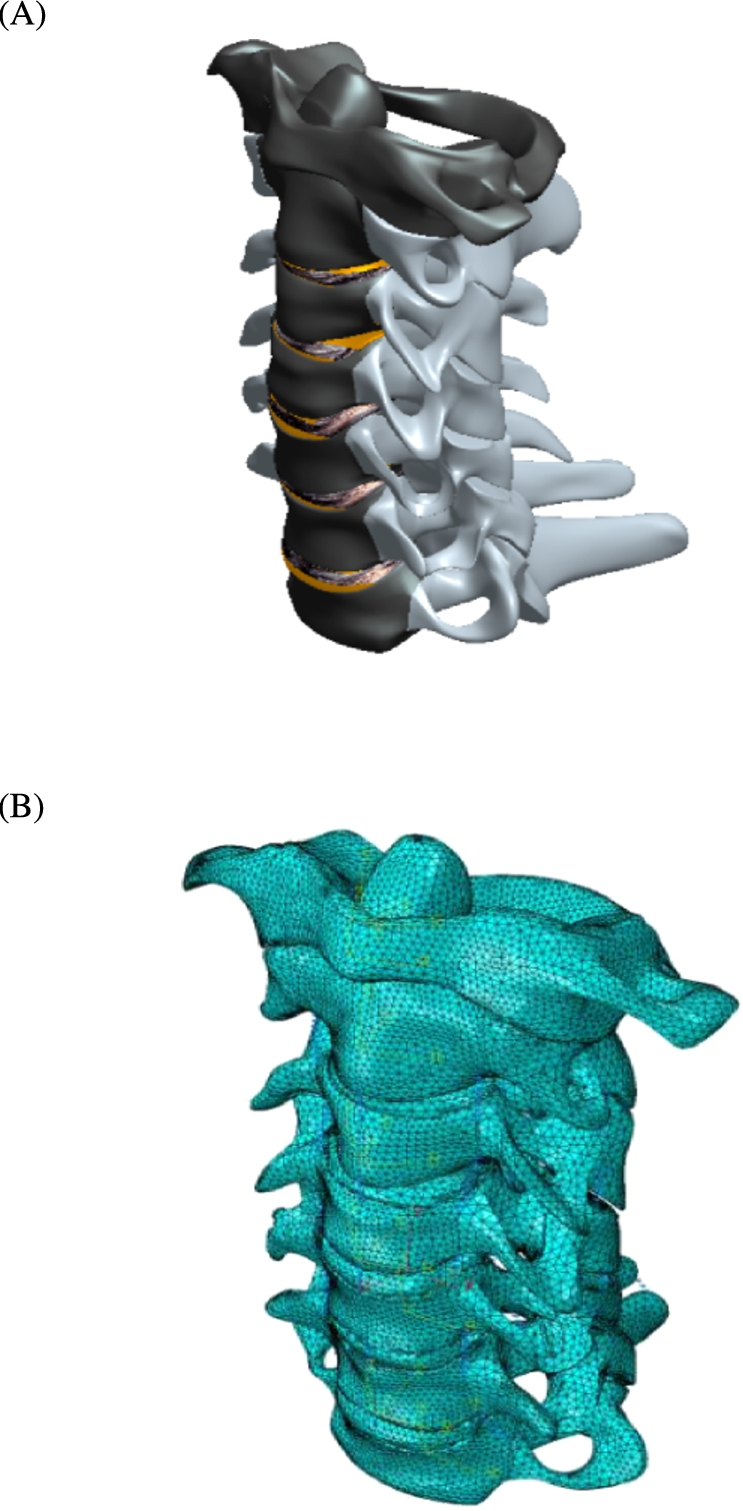
The INT Model: solid model (A); converged finite element mesh (B).
The finite element (FE) mesh of the complete solid model (INT Model) was created using an FEA software package (ABAQUS®, Version 6.13; Abaqus, Inc., Providence, RI, USA) (Fig. 1(B)). Details of the FE element types used in the meshing and the properties of all the materials in the model are given in Table 1.
Element type and elastic properties of the tissues/materials in the finite element model
ALL: anterior longitudinal ligament; PLL: posterior longitudinal ligament; SSL: supraspinous ligament; ISL: interspinous ligament; LF: ligamentum flavum; CL: capsular ligament; AlL: alar ligament; TL: transverse ligament; ApL: apical ligament. UHMWPE: ultra-high-molecular-weight polyethylene; PEEK: poly(ether-ether-ketone).
E: modulus of elasticity; ν: Poisson’s ratio. 11, 22, and 33 refer to the radial, tangential, and longitudinal axes of the bone, respectively.
The literature references are for the values of the elastic properties.
For the convergence test, 1) the meshed model was subjected to a loading of 1 Nm axial flexion moment +73.6 N compression force at the superior surface of the C1 vertebral while the inferior surface of the C7 vertebral body was rigidly fixed in position and direction; and 2) the criterion used was a change of <1.5% in the principal motion at C1–C2 of the model, between successive changes in mesh density.
In the validation exercise, the loadings used were 1 Nm axial flexion-extension moment, 1 Nm lateral bending moment, and 1 Nm axial torsional moment. Each loading was applied to the superior surface of C1 while the inferior surface of the C7 vertebral body was rigidly fixed in position and direction. Under each of these loadings, the range of motion at each of the intersegmental positions was compared to corresponding experimental results given in the literature.

The TDR Model: schematic drawing of the TDR design (10 mm in the thickness direction (A)); finite element mesh (B).
The notional TDR design comprises two endplates and a mobile insert and has three pegs on each endplate (Fig. 2(A)) that are meant to anchor the implant to the vertebral body, thereby facilitating the implant’s initial stability and, hence, its eventual osseointegration. The simulated TDR Model was obtained by modifying the INT Model thus: 1) the inferior endplate on the C5 vertebral body, the disc at C5–C6, the ALL at C5–C6, and the superior endplate on C6 vertebral body were all deleted; 2) the TDR design was placed in the resulting empty disc space (Fig. 2(B)), ensuring that there was perfect contact between the superior surface of the implant with the inferior surface of the C5 vertebral body and between the inferior surface of the implant and the superior surface of the C6 vertebral body. Four variants of TDR Model were used, the difference being in the combination of materials assigned to the mobile insert and the endplates
Materials assigned to the mobile insert and the endplates in the four variants of the TDR Model
Materials assigned to the mobile insert and the endplates in the four variants of the TDR Model
For each of the five models (INT, TDR1, TDR2, TDR3, and TDR4 Models), the loading was applied to the surface of the superior endplate on the C1 vertebral body while the inferior endplate at the C7 vertebral body was fully fixed in position and direction.
The applied loadings were: 1) 1 Nm flexion moment +73.6 N axial compression force; 2) 1 Nm extension moment +73.6 N axial compression force; 3) 1 Nm left lateral bending moment +73.6 N axial compressive force; 4) 1 Nm right lateral bending moment +73.6 N axial compression force; 5) 1 Nm counter-clockwise-acting (left) axial torsional moment +73.6 N axial compression force; and 6) 1 Nm clockwise-acting (right) axial torsional moment +73.6 N axial compression force. The axial compression force simulates the weight of the head [23] and the magnitudes of the moments are consistent with those exerted on the cervical spine during many activities of daily living [24].
Biomechanical parameters determined
For each of the five models, under each of the loadings, the principal motion at each of the intersegmental locations in the model was determined. Hence, for each combination of applied loading and variant of TDR Model, the % change in each principal intersegmental motion, relative to the value when INT Model was used, was determined.
Results
Convergence test and model validation results
The converged INT model comprised 421,160 elements and 89,161 nodes (Fig. 1(B)). Some differences were seen between the FEA results obtained using the converged INT Model and relevant experimental ones given in the literature (Fig. 3). This could be a consequence of differences in details for a given feature. For example, the present study utilized a model of C1–C7 and the loading was applied about an anatomical axis while the inferior surface was fully fixed, whereas, in the study by Panjabi et al. [37], the spine section was C0–C7 and in the study by Kallmeyn et al. [38], the loading was applied via a spinal gimbal and an XY table. It is worth pointing out that, relative to the experimental results, the trends seen in the differences with the present FEA results are comparable to those seen with results from FEA results from the literature (Fig. 4). With all these points in mind, it is plausible to conclude that INT model was validated.
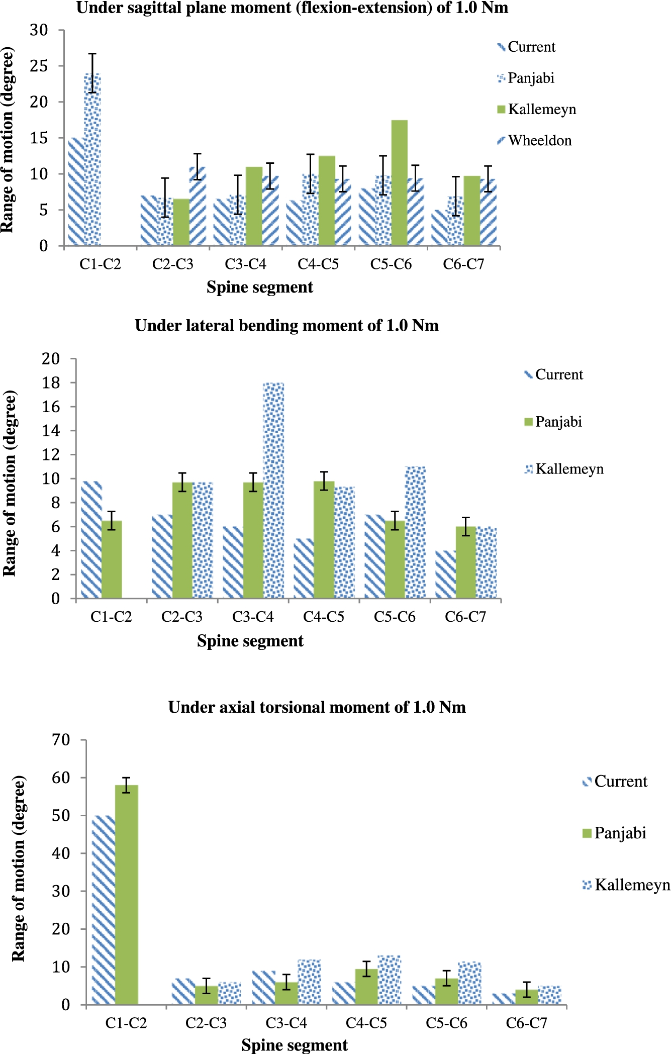
Comparison between the present FEA results from the INT Model and relevant experimental results given in the literature.

Comparison between the present FEA results, FEA results given in the literature, and relevant experimental results given in the literature.
The meshed FE model of the TDR Model (Fig. 2(A)) comprised 704,202 elements and 105,242 nodes (Fig. 2(B)).

Summaries of the present principal intersegmental motion results from the INTACT, TDR1, TDR2, TDR3, and TDR4 Models.
Summary of % changes in principal intersegmental motions under different applied loadings a
LLB: left lateral bending; RLB: right lateral bending; LTM: left (counter-clockwise) axial torsional moment; RTM: right (clockwise) axial torsional moment.
When the whole collection of results (Fig. 5 and Table 3) is considered, the overall means of the absolute values of the % change in principal intersegmental motions (relative to corresponding results when INT Model was used) were as follows: 8.4 (TDR1 Model), 10.0 (TDR2 Model), 7.4 (TDR3 Model), and 9.6 (TDR4 Model).
In the literature on FEA studies of models of the cervical spine that include simulated TDR, there are no studies on the influence of material combination, for a given replacement design, on the biomechanical responses of the model. In the present work, this issue is addressed.
Material combinations used in the parts of approved endplate-and-mobile insert type cervical TDR designs
Material combinations used in the parts of approved endplate-and-mobile insert type cervical TDR designs
Approved by the US Food and Drug Administration.
Approved by the Medicines Evaluation Board, The Netherlands.
One attractive feature of the present study is that the material combinations used reflect those used in TDR designs approved by the US Food and Drug Administration and other regulatory agencies (
There are three limitations of the study The first concerns four aspects of the geometry of the solid model. One, the facet joints were incorporated as part of the bony posterior elements, rather than as separate tissues. For a C5–C6 model subjected to 1.8 Nm flexion moment +73.6 N axial compression force, the principal motions were ∼25% greater when the facet joints were included as separate entities compared to when they were included as part of the bony posterior structures [44]. Two, the muscles were not included. However, as far as intersegmental motion is concerned, forces exerted by muscles are important when a dynamic loading is applied [45]. Three, each of the two implant-endplate interfaces was modeled as being fully bonded, implying that the simulation applied to conditions that would exist in the late post-implantation period. At each of these interfaces, a realistic contact formulation would be, for example, Coulomb friction [46]. Four, the geometrical data used to construct the model were taken from one man. Generality of results is more likely to be achieved when a parametric modeling method is used to construct the solid/geometric model [47]. The second limitation is that, in the FEA, the ground substance and the fibers in the annulus fibrosus (AF) and the nucleus pulposus (NP) were each taken to be linear, isotropic, elastic materials. Many alternative constitutive models have been given for these tissues; for example, incompressible fluid for the NP [48] and poroelasticity for both the AF and the NP [49]. For a C4–C6 model subjected to 100 N compression force uniformly distributed on the superior surface of the C4 vertebral body, the influence of the constitutive model used for the AF and the NP on mean von Mises stress was strong for some tissues, such as the inferior endplate at the C5 vertebral body, but less so for other tissues, such as the cancellous bone at the C4 vertebral body [44]. As the present study was parametric in nature, each of the aforementioned imitations applies to each of the five models. The third limitation is that only one combination of position of the center of rotation of the TDR design and its orientation in the spine model (COR location) was considered. In one literature study, it was found that COR location (axial versus antero-lateral versus lateral) exerts a marked influence on various biomechanical responses of the model, such as flexibility and force on the facets, under various loadings (flexion, extension, right lateral bending, and right lateral rotation moments) [18]. This limitation applies to each of the four variants of TDR Model.
For a model of the full cervical spine (C1–C7), with simulated implantation of a notional endplates-and-mobile insert total disc replacement design (TDR) to address symptomatic DDD at C5–C6 and subject to loadings typically experienced at the cervical spine, the material combination assigned to the parts of the design exerted a marked influence on the kinematics of the model. The
Conflict of interest
The authors have no conflict of interest to report.