
Abstract
Background:
The use of dental computer-aided design/computer-aided manufacturing (CAD/CAM) restoration is rapidly increasing.
Objective:
This study was performed to evaluate the marginal and internal cement thickness and the adhesive gap of internal cavities comprising CAD/CAM materials using two digital impression acquisition methods and micro-computed tomography.
Methods:
Images obtained by a single-image acquisition system (Bluecam Ver. 4.0) and a full-color video acquisition system (Omnicam Ver. 4.2) were divided into the BL and OM groups, respectively. Silicone impressions were prepared from an ISO-standard metal mold, and CEREC Stone BC and New Fuji Rock IMP were used to create working models (
Results:
Significant differences in the marginal and internal cement thickness and adhesive gap spacing were found between the OM and BL groups.
Conclusions:
The full-color movie capture system appears to be a more optimal restoration system than the single-image capture system.
Keywords
Introduction
Patients’ esthetic demands have increased over the years. Tooth color restorations, such as indirect composite and all-ceramic restorations, play a major role in fulfilling these esthetic demands. All-ceramic restorations are often the material of choice because of superior esthetics, color stability, biocompatibility, and resistance to masticatory forces. Many types of ceramic materials and fabrication methods are available for all-ceramic restorations. One fabrication method is computer-aided design/computer-aided manufacturing (CAD/CAM). In 1971, Duret introduced the concept of CAD/CAM application to the field of dentistry [1]. Since then, the application of CAD/CAM in dentistry has substantially increased. The CEREC system (Sirona Dental Systems GmbH; Bensheim, Hesse, Germany) uses CAD/CAM technology developed in 1980 and is one of the CAD/CAM systems currently in use. Inlays, onlays, veneers, and crowns may be fabricated and delivered in a single visit using this system [2,3]. Traditionally, a cement thickness of 50 to 120 μm has been considered acceptable [2,4,5]. In recent studies, the marginal gap of CEREC crowns reportedly ranged from 27 to 162 μm [2,6–8]. In an earlier study involving measurement of the cement thickness of 20 lithium disilicate crowns in a patient’s oral cavity using a light body silicone impression material, the average cement thickness reportedly ranged from 100 to 284 μm [9]. In fact, a cement thickness of
The purpose of this study was to evaluate and compare the cement thickness and adhesive gap of restorations fabricated using two intraoral scanners: the Cerec Bluecam and Cerec Omnicam (Sirona Dental Systems GmbH). Micro-CT was used to assess the cement thickness and adhesive gap.
Materials and methods
Master die fabrication
ISO/FDIS 12836 (Fig. 1) with a height of 7 mm, diameter of 16 mm, width of 5 mm, and taper of 16° was used. An impression of this was taken using silicone impression material (Examix Fine regular injection type; GC Dental Industrial Corp., Tokyo, Japan).
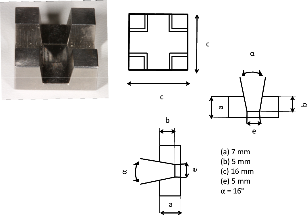
Schematic diagrams of inlay (ISO/FDIS 12836).
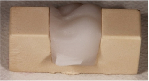
CEREC Stone BC (Sirona Dental Systems GmbH) was injected into the working model for the Bluecam, and New Fuji Rock IMP (GC Dental Industrial Corp.) was injected into the working model for the Omnicam; 10 models were fabricated and separated (Fig. 2). These were designated the BL and OM groups, respectively. When fabricating the model and shooting using the Bluecam, it is necessary to blow powder onto the model. However, because this powder causes differences in compatibility, we did not use it in these experiments (Fig. 3). Furthermore, because the margin becomes unclear and cannot be set properly if the CEREC Stone BC model is shot using the Omnicam, the New Fuji Rock IMP was used (Fig. 4) as a dental stone model material suitable for CAD/CAM. Moreover, these working model samples were examined with qualitative analysis and SEM (Miniscope® TM3000; Hitachi High-Technologies Corporation, Tokyo, Japan).
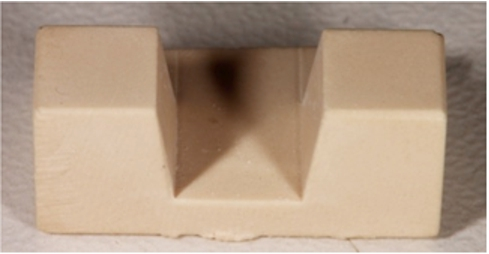
Working model.
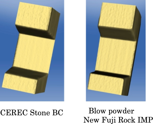
Virtual model from CEREC Bluecam scanning.
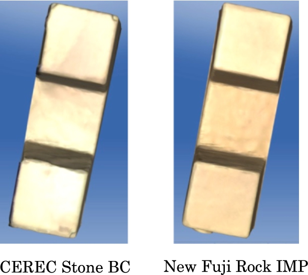
Virtual model from CEREC Omnicam scanning.
CAD system
A CEREC AC still-image capture system (Bluecam) and a full-color movie capture system (Omnicam) were used. The measurement light source for the Bluecam is a blue light-emitting diode (LED), and the camera must remain still when capturing images. Furthermore, because the auto shutter closes when the camera is still, the upper frame of the camera was fixed and continuous capture was performed while taking into account the overlaying (stitching) of the images. However, the measurement light source for the Omnicam is a white LED, and a 3D model is constructed by confocal active triangulation measurement using the video image of the measurement itself. Capture is thus performed using a freehand free-angle camera working in a non-contact manner and separated by a short distance. The inlay was designed using versions 4.0 and 4.2 of the software after taking 10 optical impressions of each of the 20 models, and the parameter values were set to a spacer of 100 μm and an adhesive gap of 80 μm. The obtained data were sent to the milling unit (CEREC inLab MC XL; Sirona Dental Systems GmbH), and the inlay was fabricated using an IPS Empress CAD milling block (Ivoclar Vivadent, Schaan, Liechtenstein).
Inlay measurement by micro-CT images
The inlays fabricated by the CAM system were each mounted on the working models without any adjustments (Fig. 5) and captured using a micro-CT unit (ScanXmate-L090H; ComScantecno, Yokohama, Japan). The capture parameters were set to an X-ray tube voltage of 61 kV, tube current of 39 μA, and magnification factor of 5.0 times. The pixel size was
Inlays on the working models without any adjustment.
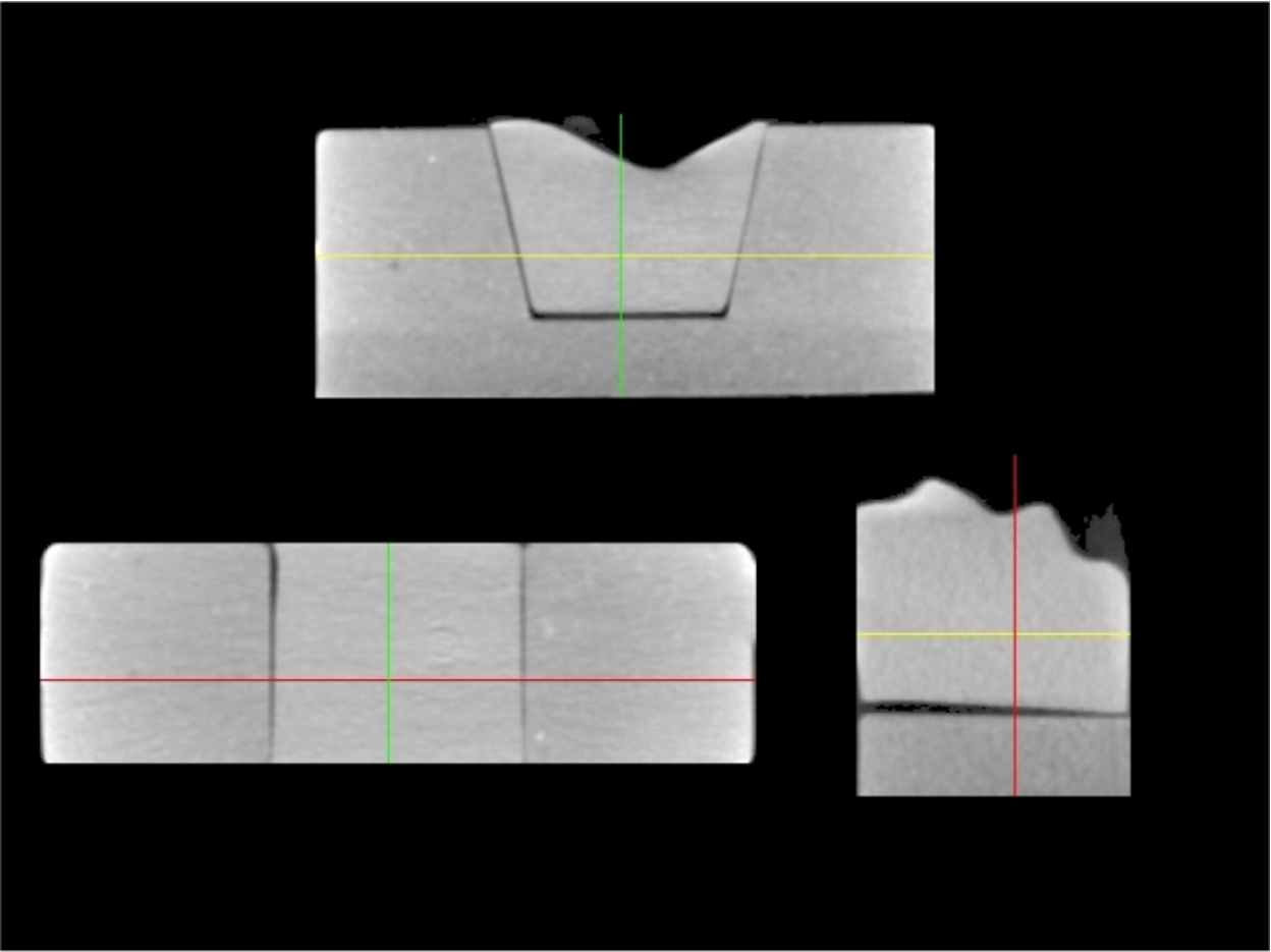
Micro-CT images of images of inlays mounted on the working models without any adjustment.
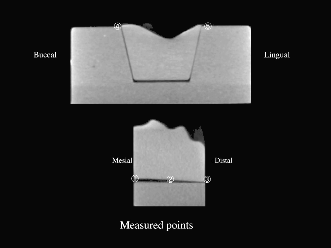
Measurement positions of the cement thickness and measurement positions of the adhesive gap.
The measurement values obtained at each measurement position in the OM and BL groups were statistically analyzed using a t-test (
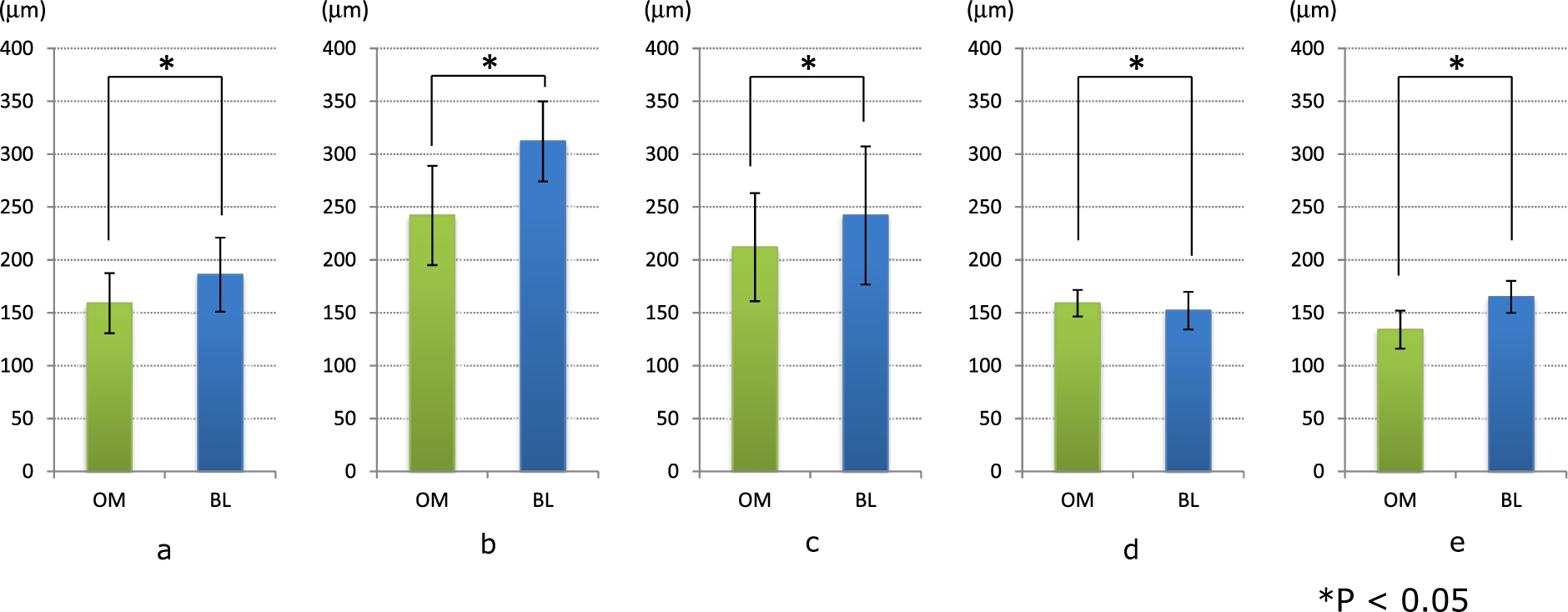
Measurement values of three measurement positions of the cement thickness and two measurement positions of the adhesive gap.
Mean values of three measurement positions of the cement thickness and two measurement positions of the advisable gap
Significant differences were found in the marginal and internal cement thickness and adhesive gap spacing between the OM and BL groups.
The mean values at each point shown in Fig. 7 were as follows: ① OM:
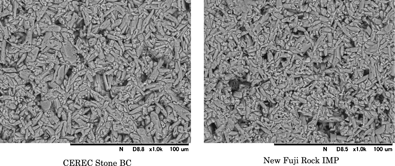
SEM images of the CEREC Stone BC and New Fuji Rock IMP surfaces.
Figure 9 shows the SEM observation findings of the CEREC Stone BC and New Fuji Rock IMP surfaces. Both gypsum materials could find to the characteristic needle-life crystal. In addition, there was no difference between the images of both in the SEM image. Table 2 summarizes the trace elements in both products as identified by SEM with an energy-dispersive X-ray analytical system. The general composition of both gypsum materials comprised calcium, oxygen, and sulfur, and the amounts were almost identical between the two materials. However, CEREC Stone BC contains titanium in a uniform distribution (Fig. 10).
Composition of the CEREC Stone BC and New Fuji Rock IMP
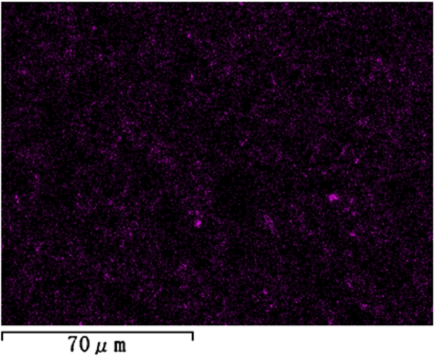
Titanium in a uniform distribution of CEREC Stone BC contain.
When creating the models, CEREC Stone BC was used for the Bluecam and New Fuji Rock IMP was used for the Omnicam. This is because when the CEREC Stone was captured using the Omnicam, the margins of the model became unclear (Fig. 4). Furthermore, when powder is blown onto the model, errors in accuracy reportedly occur due to excessive powder coating and differences in compatibility with the powder (Fig. 3). Therefore, in this study, we used the model materials that were the most suitable for each of the scanners.
This study was undertaken to compare the cement thickness and adhesive gap of inlay restorations made of a variety of CAD/CAM materials using micro-CT. In addition, the same CAM equipment was used to scan the dental casts, design the inlays, and mill the restorations.
In clinical practice long before such studies were performed, a cement thickness ranging from approximately 50 to 300 μm was anticipated [18–21]. A cement thickness of
In both of the optical imaging methods compared in this study, the light emitted from the light source inside the camera passes through a photomask to form a striped pattern of light and is projected onto the intraorally measured object after fine-tuning the optical axis using an aperture and refraction using a prism. The striped pattern of light projected onto the measured object is reflected by the surface of the object and incident on the prism, and the refracted light then passes through an aperture and is collected by an image sensor such as a charge-coupled device. The data projected onto the image sensor are converted into three-dimensional coordinate data using the triangulation method. Information about the measured data are automatically calculated by a computer, and although reproducibility is possible to some degree, differences that appear in the results are attributed to differences in the light source inside the camera and the scanning method used.
First, with respect to the differences in the light emitted from the light source inside the camera, the light reflectivity of the surface of each material differs depending on the composition of the material. The light source in the Bluecam is a blue LED; it is only blue. In addition, it does not handle object surfaces with different light reflectivities and is unable to capture a clear image. Therefore, to capture images using the Bluecam, it is necessary to suppress differences in surface reflectivities; this may be accomplished by using powder containing titanium oxide, for example. The composition analysis in the present study confirmed that CEREC Stone BC contains titanium and that the titanium was evenly distributed (Fig. 10). It follows that the blue light emitted from the Bluecam combined with the titanium in the measured object diminishes the variations in reflectivity. This allows the Bluecam to capture readable reflectance and facilitates reconstruction of the model.
In contrast, the Omnicam has a white LED with three light sources: red, green, and blue. This allows for the combination of a light projection unit that produces illumination using light of different wavelengths along the same optical axis and an imaging unit that collects and images the light reflected from the measured object. The white LED also allows the Omnicam to handle wide variations in different in surface reflectivities, and it is thought that the model can be constructed more accurately without needing to suppress variations in reflectivity using titanium.
Second, with respect to differences in the scanning method, the Bluecam captures images using a contact measurement method. Images are captured when the camera touches and affixes to the teeth. If the hand holding the camera shakes during the auto shutter operation at this time, noise occurs in the image. Furthermore, because obtaining a relatively clear image requires the operator to take several images during the scan, a large bias may be present depending on the operator’s imaging skill level.
However, because data are obtained by continuous video capture when using the Omnicam, noise due to shaking of the hands does not occur as readily, and images can be obtained regardless of the operator’s skill level. Furthermore, images are captured using a non-contact measurement method that does not involve contact with the teeth. This makes it possible to freely move the camera to any angle by hand while maintaining a short-distance separation from the tooth surface, allowing the operator to record details such as the positions of undercuts and the inner surfaces of cavities.
The differences in the 3D constructions are thought to have occurred because the same differences were present in the obtained data. For the adhesive gap, errors in parameters such as the cement thickness were not observed with either oral cavity scanner. This is thought to have occurred because more accurate values can be obtained when the oral cavity scanner is closer to the camera, allowing the measured object to be recorded more accurately than the cement thickness.
Moreover, both the oral cavity scanner and the version of the software used likely affect the compatibility. Based on a study by Shim et al. [22], highly reproducible restorations can be created using a new version of the software. In the present study, we used version 4.0 for the Bluecam and version 4.2 for the Omnicam. We believe that the compatibility can be improved by using a new software version.
Direct observation by stereoscopic microscopy, optical microscopy, and SEM and indirect observation by dye penetration were used to evaluate the compatibility state and dimensional accuracy of the restorations.
We obtained accurate values using a micro-CT unit and measuring the black gaps (transparent regions) of the cement thickness and adhesive gap in the obtained images as shown in Fig. 7. Furthermore, micro-CT images allow for examination of the internal surfaces after the restoration has set. In addition to observation of the cement thickness and adhesive gap in these images, it was also possible to observe details such as the amount of removal from internal cavities, the thickness and part of the restoration to attach [23], and the positions of air bubbles in the model. We therefore believe that observation of restorations using micro-CT would also be useful in the clinical setting.
Conclusions
Micro-CT is a very useful method with which to measure the thickness of the cement space in internal restorations. This suggests that improved compatibility can be expected in the clinical setting because micro-CT allows for accurate observation of details such as the amount of removal from internal cavities, the thickness and part of the restoration to attach [23], and the positions of air bubbles in the model. Furthermore, with respect to different types of intraoral scanners, this study suggests that restorations with better compatibility can be created using the full-color movie capture method than the still-image capture method.
Conflict of interest
The authors have no conflict of interest to report.