
Abstract
Background:
Stenting has been proposed as an effective treatment to restore blood flow in obstructed arteries by plaques. Although several modified designs for stents have been suggested, most designs have the risk of disturbing blood flow.
Objective:
The main objective is to propose a stent design to attain a uniform lumen section after stent deployment.
Methods:
Mechanical response of five different designs of J & J Palmaz-Schatz stent with the presence of plaque and artery are investigated; four stents have variable strut thickness of different magnitudes and the rest one is a uniform-strut-thickness stent. Nonlinear finite element is employed to simulate the expansion procedure of the intended designs using ABAQUS explicit.
Results:
The stent design whose first cell thickness linearly increases by 35 percent, exhibits the best performance, that is it has the lowest recoiling and stress induced in the intima for a given lumen gain. It also enjoys the minimal discrepancy between the final at the distal and proximal ends.
Conclusions:
A uniform widened artery can be achieved by using the stent design with 35 percent increase in its first cell, which provides the possibility to prevent from disturbing blood flow and consequently post-operation complications.
Introduction
Atherosclerosis is the most common arterial wall diseases. It is also responsible for almost one-third of all fatalities worldwide. The atherosclerotic lesion increases the arterial wall thickness, partially or totally occludes the arterial lumen and finally reduces blood flow [1]. Balloon angioplasty is a treatment which is performed to restore vessel patency. The limitations of this treatment such as the elastic recoil of the artery has caused the introduction of the cardiovascular stents [2,3].
Literature studies show that the interaction between stent and artery is an important issue in cardiovascular treatments so that vascular injury causes restenosis. It has been demonstrated that the stent design has a significant effect on arterial injuries including thrombosis and hyperplasia [4–7]. Optimization of stent design, inflation pressure, balloon selection, etc. are the factors that can be used in order to reduce vascular injury [8]. Therefore, cardiovascular treatment needs a precise study before stent deployment to avoid long-term failure.
From a mechanical viewpoint, stent expansion is a nonlinear process the simulation of which could not be performed by analytical methods. This method usually needs to be dealt with by numerical approaches. Amongst these numerical approaches, finite element method (FEM) is known as an appropriate way that gives researchers a wide insight into the process of stent deployment. In this regard, many computational studies have been performed to study the expansion of stents with or without presence of artery. Some researchers have investigated the expansion procedure of different stents as well as the influence of geometrical parameters such as length, diameter, and thickness of strut on the free expansion of stents [2,5,9,10]. On the other hand, the effects of the geometry of stents on the artery have been studied in several works. Prendergast et al. [3] developed a constitutive model for vascular tissue by using the experimental data of porcine aorta and human femoral artery. Then they employed finite element method to calculate the prolapse after placement of four different stents. Chua et al. [11] described the characteristic expansion of the J & J Palmaz-Schatz stents with the presence of plaque as well as the artery. The results of investigating relationship for balloon-artery contact stress and the distance between two adjacent stent struts has been published in reference [8]. Wu et al. [12] simulated the expansion of a stent which was their patent design in a curved and a straight artery. Lally et al. [13] examined the levels of injury occurred in the arteries in which two different stents were deployed. Auricchio et al. [14] concentrated on the deployment of J & J Palmaz-Schatz like stent. They showed that the non-uniform expansion of the stent caused creation of areas of non-uniform contact pressure. Qiao and Zhang [15] specified the relationship between the in-stent restenosis and the shape of the stent links. Schiavone and Zhao [16] studied the effects of various boundary conditions, balloon types, and artery constitutive models on the results of the stent expansion. Holzapfel et al. [6] performed a parametric study to evaluate the influence of different stent geometrical parameters on the artery. Their study included three different stent designs.
In the stent deployment process, since the balloon applies a uniform pressure on the inner surface of the stents, they expand non-uniformly so that the diameter of the artery is lower where there is a thicker plaque. It is thought that the occurrence of hyperplasia, renewed atheroma, and emboli after stent deployment due to sudden expansion of the vessel may lead to post–operation complications. Disturbed blood flow emanating from non-uniform stent expansion may be responsible for these complications [17]. Therefore, due to the fact that the blood disturbance should be reduced as much as possible, the authors of current paper decided to investigate the expansion behavior of the J & J Palmaz-Schatz stents in which the thickness of the first cells decreases linearly in the longitudinal direction. This change causes the stent to have a varying flexibility along its length. This design paves the way for achieving more uniform vessel after stent deployment. Moreover, the stress values induced by different stent designs due to different loading profile were investigated.
FEM modeling
Geometry
Due to circumferential and longitudinal symmetry, only one-eighth of the models were used. The balloon was modelled as shell surface with 1.13 mm radius. The inner radius of the plaque was chosen to be 1.52 mm and 1.815 mm at distal and proximal ends respectively. The thickness of the plaque at distal and proximal ends were modelled to be 0.4 mm and 0.105 mm respectively. The inner diameter of the artery equaled outer diameter of the plaque. The 0.5 mm thickness of the artery consisted of the three layers of adventitia with 0.236 mm thickness, media with 0.144 mm thickness, and intima with 0.12 mm thickness.
Five different stent models were selected to be investigated; the first cells of these stents had a similar structure and different dimension; that is, the thickness of the cell decreased linearly from the proximal end. The only difference was in the reduction rate of thickness (one of these stents, has a zero reduction rate of thickness in the first cell; that is, the first cell and thus the whole of stent had a uniform thickness). Therefore, the difference of these five stent models embedded in the structure and dimension of the corresponding first cells. The uniform stent model and all other models (except their first cells) had strut thicknesses of 0.08 mm. Other four models, at the proximal end of the stent, had thicknesses of 25, 35, 45 and 55 percent more than that of the uniform parts; these stents are denoted in this paper by I25, I35, I45 and I55 respectively. The uniform-thickness-strut stent is denoted by U design. All five models were considered to have 8.66 mm length, 0.1 mm strut width, 40 equally spaced slots, and 2.51 mm outer diameter. Fig. 1(a) shows the general geometry of the stents. For more convenient comparison between designs, Fig. 1(b) depicts the stent thickness. Parameter s in this figure, is defined in Table 1 for each model. The inner surface of the slotted tube was not in contact with the outer surface of the balloon at the beginning of the analysis.
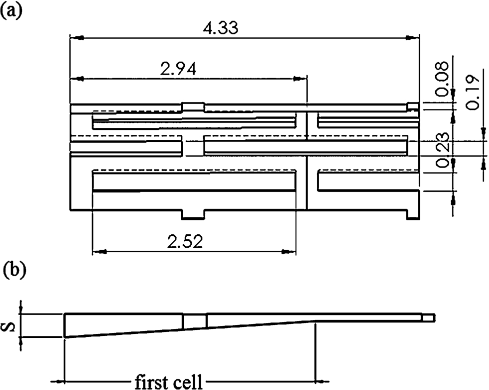
(a) General geometry of the stents (half), (b) stent thickness.
Parameter S for different designs (mm)
The stent models, the artery, and the plaque were meshed with 8-node brick elements. The stents models including U design, I25, I35, I45, and I55, were meshed with 1080, 1196, 1354, 1560 and 1836 elements respectively. The plaque and the artery were meshed with a total number of 6099 elements. Each layer of the artery was discretized by two elements through its thickness. The balloon model was discretized by 1518 4-node elements. These mesh densities were chosen based on a mesh sensitivity analysis. Figure 2 depicts the finite element model of the components corresponding to the U design model.
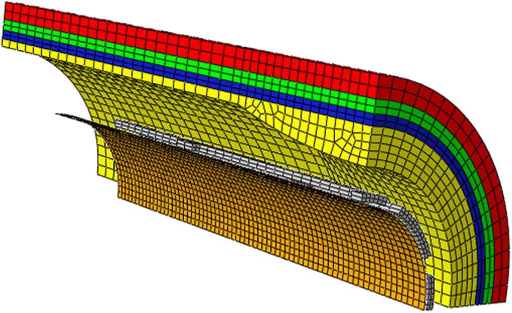
Finite element model.
An ogden hyperelastic constitutive equation was used to model the plaque and the layers of the artery [16,18]. The balloon was defined by a Mooney–Rivlin hyperelastic material. The non-linear mechanical behavior of these components can be adequately described by hyperelastic constitutive models [17,19]. The strain energy function W for an isotropic solid can be given as a function of the principal invariants
Material properties
Material properties

Load profile in the first case study.
Nodes at symmetry planes and edges were restrained in normal direction with respect to the planes of symmetry for all the components. Nodes at proximal end of balloon were fixed. All the nodes at proximal end of the artery were tethered in all directions. Nodes at proximal end of stent were allowed to move freely [11].
Loading and solution
In the current work, two case studies were considered. In the first case study, a trapezoid-shaped loading with the same maximum load was applied to the inner surface of the balloon as suggested by [11]. The pressure increased linearly to a maximum of 1.65 MPa for 21 ms, which was sustained for 6 ms and then vanished in 10 ms. These values were chosen such that the stress induced in the artery and simulation time became minimum. Figure 3 represents the load history of first case study. In the second case study which was similar to the work of [4], trapezoid-shaped loadings with different maximum loads were applied in order to achieve the same final diameter at distal part of the artery, which is equal to the final diameter of the artery expanded by the uniform thickness stent in the first case.
ABAQUS finite element software was utilized to perform the simulation. ABAQUS explicit with general contact was used to analyze the whole finite element model. Frictionless interaction was defined. In order to ensure that dynamic influences were negligible, the kinetic energy was controlled throughout the whole simulation. It was not notable in comparison with the total energy.
Results and discussion
In the first case study, the effects of usage of different stent designs under subjection of the same load profile were investigated. In other words, the main aim of the case study 1 was to compare the characteristic behavior of modified and unmodified stents as well as the influence of these stents on the arterial wall when the same maximum expanding load was employed. Figure 4 demonstrates that, regardless of stent design, the areas with stress concentration are located in the corners of slots, whereas the middle of the struts have the lowest stresses. The plastic deformation in the hinges allows the stent to expand [2]. It can also be observed that increasing the thickness up to 35 percent would result in widening the total low-stress regions. More increase in the thickness reduces such regions.
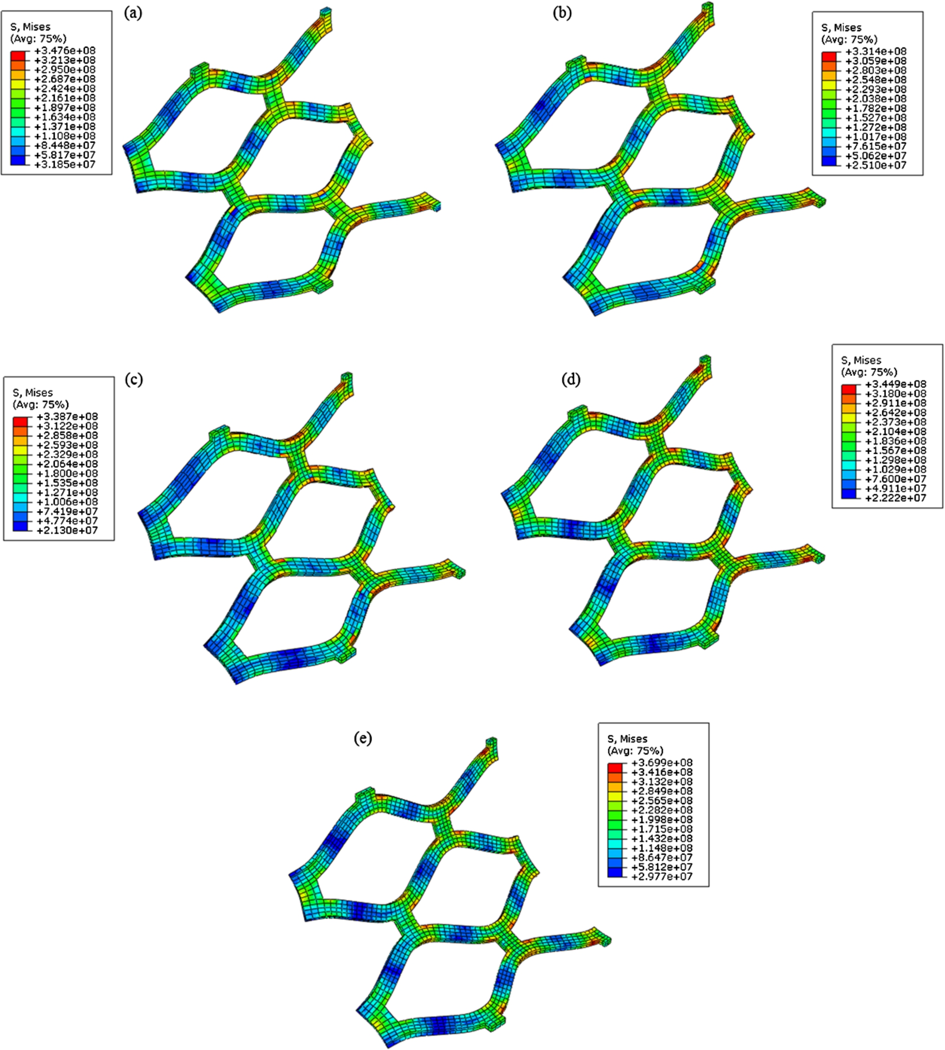
Distribution of Von misses stress in the (a) U design; (b) I25; (c) I35; (d) I45; (e) I55.
Figure 5 shows the distribution of the Von Misses stress in the stenotic artery. Maximum stress can be observed at distal part of the plaque. Therefore, this part of the plaque is more likely to be ruptured. The stress concentration at distal part of the plaque has been attributed to the different stiffness of the plaque and the stent, as well as outstanding curvature of the plaque geometry [11]. The stress decreases gradually along the artery from distal to the proximal. These results are in agreement with [11] in which it is reported that the plaque is more likely to be ruptured at distal end than other parts.
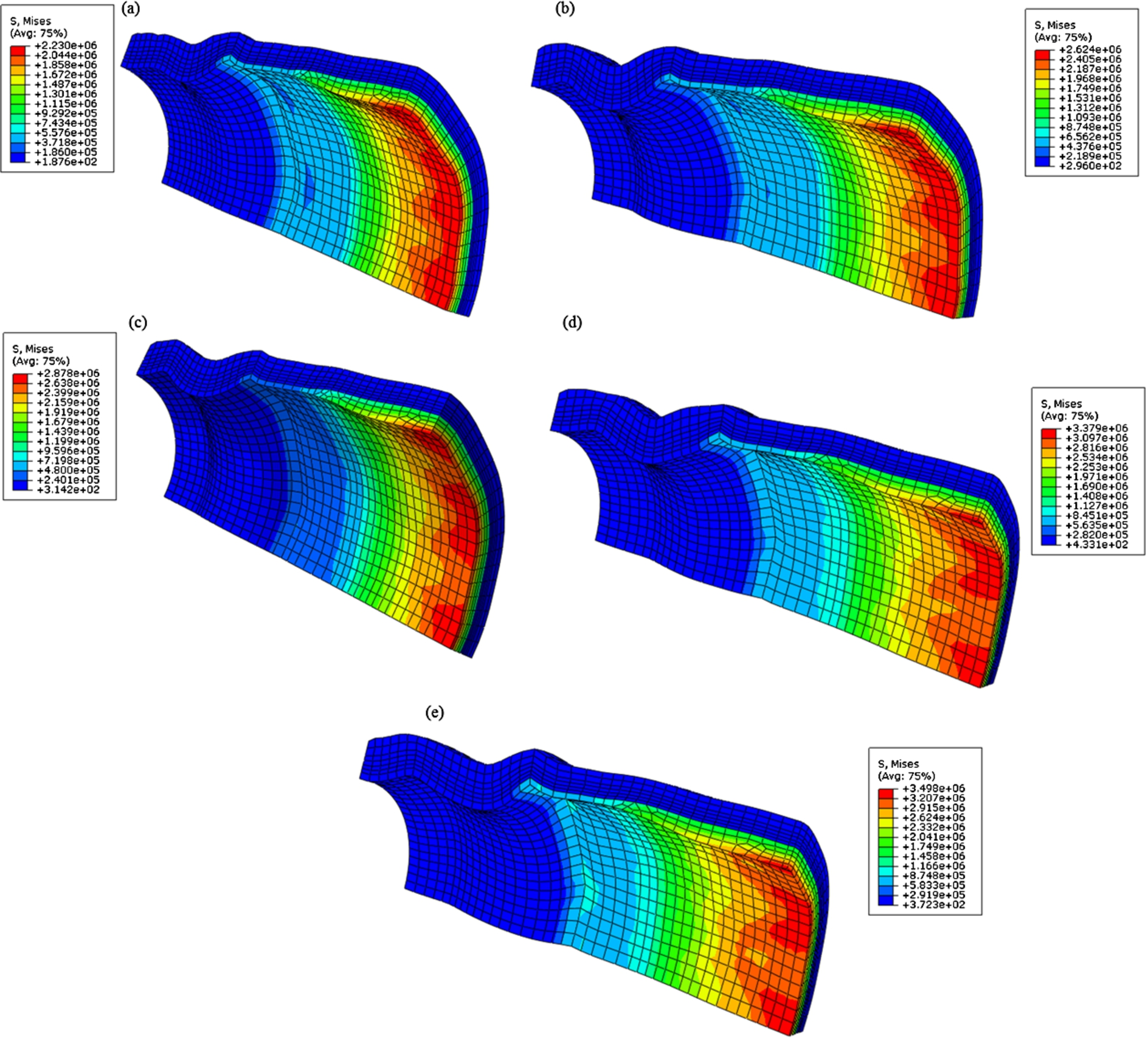
Distribution of Von misses stress in the plaque and the artery due to implantation of (a) U design; (b) I25; (c) I35; (d) I45; (e) I55.
When a stent expands to a specific diameter and then the balloon pressure is removed, its diameter magnitude decreases to a lower value which is known as radial recoil. The radial recoil is the effect of external pressure exerted by the artery and internal stress of the stent [20]. In this work, radial recoils at distal and proximal parts were measured. It was found that all the designs have significantly higher radial recoil at distal part of the artery. This is due to existence of the thicker plaque at the distal end of the artery. It was also found that I25, I35, I45, and I55 have lower radial recoil than the U design. This is due to the fact that the thicker stents have higher radial strength which enables it to resist higher compressive pressure [4]. I45 and I55 have higher radial recoil than I25 and I35 at distal part. Table 3 gives the radial recoils, foreshortenings and the diameters of the designs after removal of the pressure.
Figure 6 shows the inner diameter of each design with respect to the expanding pressure at maximum load. It is observed that the expansion rate of the U design is more than those of other designs when the applied pressure is between 1 to 1.4 MPa. At the pressure of 1.65 MPa, the diameter of the U design, I25, and I35 are approximately equal, and lower than those of I45 and I55. It can be inferred that the sustained pressure has caused more increase in the diameter of I25 and I35 than that of the U design so that the final diameter of the U design is less than final diameter of the I25 and I35. The medical aim of the application of the stents is to provide a stable scaffold inside the artery in order to prevent the artery from prolapsing. Therefore, the radial stiffness of the stents is an important regard for the stent designing [11] which necessitates production of stents with lower radial recoil. This is the major factor, responsible for luminal loss, to avoid subsequent problems.
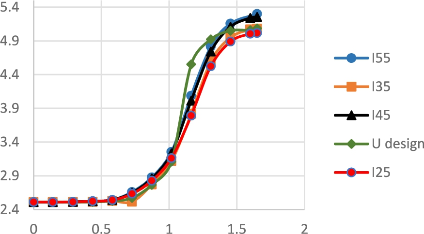
Outer diameter of the designs with respect to the pressure.
Results corresponding to the first case study
One of the important clinical factors of stent implantation is the lumen gain, which is directly pertains to the final inner diameter of the stent. Final diameter of the artery at distal and proximal ends was measured and reported in the Table 3. The final diameter of the stents, and consequently final diameter of the artery, increased with the increase in strut thickness. This is in good agreement with [4], which showed that thicker stents expanded more than thinner ones. An interesting result is that the discrepancy between the final diameter of the artery at the distal and proximal ends of the stent was the lowest for the I35 which suggests that by using this design more uniform arterial section can be achieved. The uniform arterial section avoids the disturbed blood flows, and consequently, reduces the likelihood of the atheroma [17].
Foreshortening is an undesirable feature of stents which can adversely influence the positioning of stents [10]. The foreshortening of each design was determined; see details in Table 3. The U design and I55 have the lowest and highest amount of foreshortening respectively. In other words, the increase in the first cell thickness causes the increase in the foreshortening. As it was mentioned, thicker stents expand more than thinner ones and have higher final diameters as well. Therefore, the higher expansion leads to higher foreshortening of the thicker stents.
Figure 7 shows the maximums of different stress components in the intima layer and plaque induced by different designs. The design was found to have an important effect on the magnitude of the stress in the plaque and artery. The von misses stress which considers the effect of all components of principal stress together is of utmost importance. The maximum von misses stresses induced in the plaque by I25, I35, I45, and I55, were 17.54, 29.11, 51.54, and 56.9 percent higher than that of U design respectively. The highest stress in the intima layer was found to be occurred by the I55, which is 54 kPa greater than the maximum stress induced by U design. The discrepancies between maximum stress values induced by the I25, I35, I45, and that of U design were 15, 22 and 48 kPa respectively. The higher maximum induced stresses can be attributed to the higher final inner diameter of the stents. It can be concluded that the more the increase in the thickness of the first cell of the stent, the more increment in the maximum stress is caused. However, the smallest compressive max principal stress in the intima were for I25 and I35. The importance of stress induced in the artery during the stent expansion is that the stress may play a chronic stimulating role in cell proliferation. Cell reproduction is a stress-relieving response by vessel thickening [4] which may lead to in-stent restenosis. As a result, the stents by which the lower stress is occurred in the artery is clinically preferred. However, it should be noted that the lower stress should be induced whereas other important factors such as lumen gain are not manipulated.
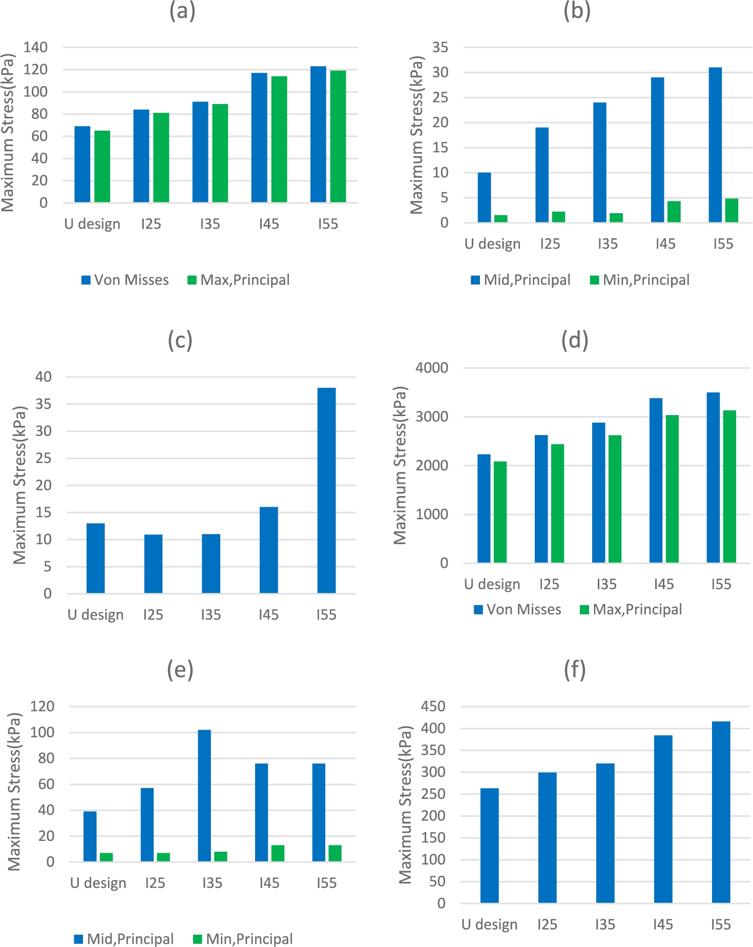
Maximum stress components in the Intima (a) von misses and max principal; (b) mid and min principal; (c) compressive max principal and in the Plaque; (d) von misses and max principal; (e) mid and min principal; (f) compressive max principal in the case study 1.
The main objective of case study 2 was to investigate the effect of stent designs on the artery when the aim of angioplasty is achieving a certain lumen gain. Therefore, in this case study, the magnitudes of the maximum pressure were chosen in such a way that inner diameter of 4.79 mm, which was equal to the inner diameter of the artery expanded by U design in the first case study, would approximately be achieved. Figure 8 illustrates the profiles of the loadings applied to the inner surface of each design. The results demonstrated that in the case of the same final diameter, thicker stents need lower maximum loads. The maximum pressure needed for I55 was 1.528 MPa, which was 7.4% lower than that of U design. Maximum loads for I25, I35, and I45 were 1.616, 1.588, and 1.548 MPa respectively. Therefore, it is obvious that the same lumen gain can be achieved by applying lower pressure on the inner surface of the thicker stent.

Loading profiles in the case study 2.
Figure 9 depicts the maximum von misses stress along with maximums of components of principal stresses in the plaque and the intima layer. It can be observed that mid principal stresses for modified designs in both plaque and intima and compressive max principal stress for I25 and I35 induced in the plaque were more than those of U design. However, all other stress components are less for modified designs in comparison with the U design. Among modified stents, although the discrepancies in the stress components were not remarkable, the minimum von misses stress in the intima induced by I55 and I35 and minimum von misses, tensile max principal stress, and compressive max principal in the plaque were for I55. As mentioned before, cell proliferation compels cardiologist to use the stents by which the lower stress induced while higher lumen gain is obtained. The results of this case study showed that the I35 and I55 stent design has these advantages.

Maximum stress components in the Intima (a) von misses and max principal; (b) mid and min principal; (c) compressive max principal and in the Plaque; (d) von misses and max principal; (e) mid and min principal; (f) compressive max principal in the case study 2.
One of the most important problems in the stent placement corresponds to the non-uniform expansion of these biomedical devices. This problem can be ascribed to the different thickness values of the plaque at different parts along the artery which causes the stents to recoil non-uniformly at these parts. In this paper, it was tried to obtain conditions according which the stent expansion would occur in a uniform manner. In this direction the effect of geometrical parameters on the expansion behavior of five stents with J & J Palmaz-Schatz design were investigated. In order to numerically study the stent delivery procedure, nonlinear finite element simulation was utilized. The thickness of the first cell of the stents was a distinguishing, geometrical factor. Four stents had variable strut thickness of different magnitudes while the other was a uniform-strut-thickness stent.
In the first case study of the current work, the same load profile was applied to all five designs. Thus the mechanical responses along with their effects on the artery were investigated. The results showed that the recoiling behavior of the stent could be improved when the thickness of the first cell would increase up to 35 percent. Moreover, the most uniform section in the stented part of the artery can be achieved by using I35. In the second case study, different load profiles were applied to all designs. The results of this part indicated that all modified designs caused lower von misses stresses in the plaque and the intima layer. The lowest maximum von misses stress in the plaque induced by I55 and in the intima layer induced by I55 and I35. According to the results, it seems that there exists an optimum point for the strut thickness in which the design could results in improved mechanical responses such as minimal recoiling, lower magnitudes of stress induced in the artery, and uniform expansion; the latter is a decisive factor in the success of a stent deployment process. Future works include investigating and determining such optimal design satisfying experimental constraints of fabrication.
Conflict of interest
The authors have no conflict of interest to report.