
Abstract
This study investigated the effect of three different parameters of a dental implant on stress and strain values in the peri-implant bone by finite element analysis. In this work, the effect of diameter, length and elastic modulus on the biomechanical behavior of a new dental implant was simulated using the finite element method. A three-dimensional model of a mandible segment corresponding to the premolar region and twelve dental implant models were obtained. Loads in three directions were distributed on the surface of the coronal area of the dental implants. The dental implant models were obtained in the FreeCAD 0.16 software and the simulations were made using the Abaqus/CAE software. In all cases, higher stress concentrations were obtained in the peri-implant cortical bone between 40.6 and 62.8 MPa, while the highest levels of strain were observed in the peri-implant trabecular bone between 0.002544 and 0.003873. In general, the highest von Mises equivalent stress values were observed in the peri-implant cortical bone. However, in this bone, both the maximum von Mises equivalent stress values and the von Mises strain are similar or inferior to those reported in different studies by finite element for other models of dental implants under immediate loading. Maximum von Mises strain values were observed in peri-implant trabecular bone. However, in this bone strains levels were obtained that maintain bone density or increase it. The effect of the three simulated variables (implant diameter, length, and elastic modulus) have a statistically significant influence on the von Mises equivalent stress and in von Mises strain values.
Background
The use of osseointegrated dental implants for functional and aesthetic rehabilitation of patients with partial or total edentulous has increased in recent years [1]. However, different factors may affect the long-term implant success. Within these factors, the biomechanic aspects play a key role in its in vivo behavior [2]. It is reported that stresses or strains in excess and/or defect in the maxillary bone can affect the dental implants osseointegration, as well as decrease peri-implant bone density [1]. In addition, the excess and/or defect of stresses/strains in the peri-implant bone can increase the crestal bone loss. According to most studies, occlusal overload is the main factor for crestal bone loss around endosseous dental implants. Several studies have aimed to reduce crestal bone loss by increasing the contact area of bone-implant interface and therefore reducing stress and strain at the cortical alveolar crest [3].
At present, the use of dental implants under immediate loading conditions has increased because the duration of treatment is significantly shorter and decreases the number of operations [4]. In addition, clinical studies have found a satisfactory survival rate of immediate loading implants [5]. Despite the promising results of immediate loading protocols obtained in experimental and clinical studies, failures can still occur and it has been suggested that they can be related to biomechanical factors [1]. A high peri-implant bone loss and early implant failures associated with some immediately loaded situations are also reported [6]. Besides, the simulation by finite element method (FEM) of dental implants under this protocol showed an increase in stress and strain levels in comparison with implant under the conventional protocol [7].
A significant factor in the biomechanical behavior of dental implants is the manner in which stresses are transferred through the implant to the peri-implant bone. It is influenced by factors related to the implant design and with the material used in its manufacture [8]. By finite element simulation, it has been found that the implant design parameters (diameter, length, and shape) have influenced its biomechanics [9]. In addition, in screw implants, the thread parameters (profile, pitch, depth, width) also influence the stresses and strains obtained in the peri-implant bone.
The stress and strain levels in the peri-implant bone are related to the area of bone-dental implant contact. The increase of the contact area of bone-implant interface has generally been obtained by increasing the diameter and/or the length of the dental implant or altering the fixture design/shape [3]. It has been demonstrated that implant diameter is more important on stress and strain levels in peri-implant bone than implant length or implant geometry [10,11]. However, stress levels in both cortical and cancellous bones may be reduced when the implant length is increased. It is also possible to increase the area of bone-implant contact by modifying the threads. Commonly, the screw thread profiles used in dental implants are triangular, square, trapezoidal, buttress and reverse buttress [9,12]. The square thread profile has the largest area and generates less shear stress in the peri-implant bone. In several studies, the influence of the thread pitch, profile, thread depth and the thread width on the stress and strain levels in the peri-implant bone have been studied [9,13]. Among these factors, it has been found that the thread pitch has the greatest influence on both stress and bone strain levels as well as on the primary stability of the implant [14]. Kong et al. [15] recommend using a thread pitch exceeding 0.8 mm for a screwed implant for biomechanical considerations. However, Lee [14] reported that square thread with a 0.6 mm pitch has an optimal contact area and the best bone stress values.
Some factors that are not related to the geometry of the dental implant also affect its biomechanical behavior. For example, it has been found that the load type (direction), the magnitude of the load, as well as the bone quality show a significant influence on the stress and strain levels in the peri-implant bone [14]. In some studies, it has been found that the type of load has a greater effect, while in others it is reported that bone quantity and quality are the most significant factors [2]. The magnitude of the stresses and strains in the peri-implant bone is directly related to the force applied to the implant during chewing [16]. Overloads can produce peri-implant bone resorption or fatigue failure of the implant, whereas low loading of the bone may lead to atrophy and subsequent bone loss [17]. In addition, during the chewing, the axial load (coronal-apical direction) is favored in dental implants. However, lateral forces (distal-mesial and bucco-lingual directions) have also been found to influence its biomechanics [17].
Bone density is an influential factor in bone quality and may vary in both cortical and trabecular bones, depending on the locations, ages, genders, and health status [18]. In addition, the bone is an anisotropic and inhomogeneous material and its mechanical properties are dependent on the direction of the applied load [9]. According to the classification of Zarb and Lekholm [19], four bone quality categories were established, from type I (homogeneous cortical bone without trabecular bone) up to type IV (with a core of low-density trabecular bone and a thin layer of cortical bone). In the peri-implant cancellous bone with low density, an increase of the strains in comparison with the cancellous dense bone is observed. In addition, the stresses and strains distribution is related to the thickness of the cortical bone and overall available bone height in relation to the size of the implant [3]. For this reason, in clinical situations with poor bone quality, it is necessary to use long and wide implants.
The remarkable differences between the elastic modulus of the implants’ material (100–110 GPa) and cortical bone (10–30 GPa) imply that the stresses are not correctly transmitted to the peri-implant bone (stress shielding), causing bone resorption and the eventual loosening of the implant [20]. This problem can be solved by decreasing the elastic modulus of the dental implant material, as a result of increasing dental implant porosity. The porous structures are characterized by their low density, low elastic modulus, and great surface area. These characteristics stimulate the peri-implant mineralization and rapid healing of the bone tissue formed and increase the bone-implant contact surface.
Nowadays, the biomechanical behavior of dental implants is evaluated by finite element analysis (FEA), using three-dimensional models [21]. The aim of this study was to simulate the effects of diameter, length and elastic modulus of a dental implant on stress and strains levels in the peri-implant bone under immediate loading.
Methods
Design of the models
The FreeCAD 0.16 software was used in 3D modeling. The 3D finite element models comprised a segment of mandible corresponding to the premolar region (cortical bone, and cancellous bone) and the dental implants (Fig. 1a). The mandible model (bone type D2) had dimensions of 15 mm in length (mesial-distal direction), 32 mm in height (coronal–apical direction) and between 9–15 mm in width (bucco-lingual direction). In addition, the thickness of the cortical bone used was about 2 mm. Four designs of a new conical dental implants were obtained, with a square or rectangular thread, a thread pitch of 1.2 mm (Table 1). They also present variable height of their threads in the contact zone of trabecular bone-implant and two threads in a zone next to their necks. These dental implants differ in length and diameter (Table 1). In addition, models of the implant were integrated into the mandible segment in order to perform the finite element analysis (Fig. 1b).
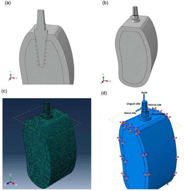
Cross-section of the three-dimensional model (A), three-dimensional model (B), finite element mesh in model 1 (C), loading condition and boundary conditions (D).
Experimental design
A multi-level factorial statistical design was used to determine the main and interactive effects of three variables on maximum equivalent von Mises stress (VMES) and von Mises strains (VMS) in the cortical and trabecular peri-implant bone: implant diameter (implant neck diameter), implant length (thread length), and the elastic modulus of the implant material. Implant diameter ranged from 3.8 to 4.5 mm, implant length from 10 to 13 mm, and elastic modulus implant from 40000 to 110000 MPa, resulting in 12 implant designs (Table 1). The three elastic moduli used in the simulation by the finite element method corresponded with a dense Ti6Al4V alloy and Ti6Al4V with porosities of 17 and 40%.
Statistical analysis was performed using Statgraphics Centurion XV software (Statpoint Technologies, Inc., USA). Statistical analysis of the maximum von Mises equivalent stress (VMES) and strains (VMS) was performed using an Anova test and a level of significance (p < 0.05) was considered statistically significant.
Finite element analysis
The software Abaqus/CAE (Simulia, France) was used to simulate the stresses and strains in the peri-implant bone. The mechanical properties of the implant (Ti6Al4V alloy) were assumed homogeneous, isotropic, and linearly elastic. Three elastic moduli of the implant material were used in the simulations by finite elements. Also, the mechanical properties of the cortical and trabecular bones were taken as non-homogeneous, anisotropic and linearly elastic. The specific values of the properties were taken from different studies and are listed in Table 2.
Properties of the implant (Ti6Al4V) and cortical and trabecular bones used in the simulations
Properties of the implant (Ti6Al4V) and cortical and trabecular bones used in the simulations
The models were discretized with tetrahedral elements of ten nodes and the sensitivity of the mesh was defined from mesh convergence tests for model 1 (Fig. 1c). All models were meshed with tetrahedron elements, because the tetrahedrons are used in complex geometries, because they adapt better, with less initial distortions to these conditions. A global mesh with elements of 1 mm and a local mesh with elements of 0.1 mm (Fig. 1c) was elaborated in the contact areas implant - trabecular bone and implant - cortical bone. The final mesh adopted for each model ensures errors of less than 1% in normal contact stress. The results of these tests yielded 73600 elements for the cortical, 435828 for the trabecular 568181and for the dental implant.
According to Himmlova et al. [11], the implants were loaded with static forces of 17.1 N, 114.6 N, and 23.4 in the bucco-lingual, axial (coronal–apical), and mesial directions, respectively (Fig. 1d). These loads simulated the average mastication force (118.2 N) in a natural, oblique direction (forming an angle of approximately 75° to the occlusal plane). Loads in three directions were distributed on the surface of the coronal area of the dental implants. In addition, they were introduced into the software as pressures of 46.23 MPa, 3.8 MPa and 9.52 MPa in the axial, buccal-lingual, distal-mesial directions, respectively.
Figure 1d shows the boundary conditions of the models. The boundary conditions included constraining all three degrees of freedom at x, y, and z directions (cortical and trabecular bones). Two contacts were simulated, the first kind of tie for the interaction between the bones and the second kind surface to surface between the dental implant and the bones, designated contact properties as normal behavior, and tangential behavior where a coefficient of friction of 0.3 is declared.
Results
Distribution and values of stress and strain were obtained using von Mises equivalent stress (VMES) and von Mises strain (VMS). In different FEA, the VMES have been reported to summarize the general stress state at a point [23]. In all simulated runs, the highest levels of stress were observed in the implants’ coronal area ( <140 MPa), specifically in the area of the section change between the hexagon and the implant neck.
Stress and strain distribution patterns in the cortical bone
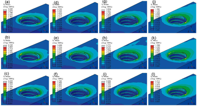
The stresses may occur as tensile and compressive, shear or a stress combination known as equivalent von Mises stresses [28]. Figures 2 and 3 show VMES and the VMS distributions in the cortical bone. In general, the simulated runs generated the VMES highest values in the peri-implant cortical bone of the distal site. It was observed that stresses were concentrated in both the outer cortical bone region and along the axial direction of the interface between the cortical bone and neck implant. Maximum VMES values (between 40 and 60 MPa) are obtained in these areas (Fig. 2a, Table 3). The minimum VMES values in the peri-implant cortical bone (between 0.7 and 0.9 MPa) were concentrated in the mesial site, a result that must be related to the direction in which the loads were applied to the implant. In addition, Figs 8 and 9 show the distribution patterns of maximum and minimum principal stress in the cortical bone. In general, the simulated runs showed the highest values of minimum principal stress in a similar location in comparison to the one presented by the highest values of VMES. On the other hand, the high maximum principal stress area was localized along the bone in contact with the implant neck. Maximum principal stress values were observed in the interval between 12.1 and 32.5 MPa, while the minimum principal stress values were between −62.3 and −105.2 (Table 5).

Von Mises equivalent stress distribution patterns in the cortical bone. The letter corresponds with the experimental run.
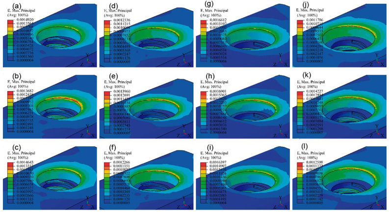
Von Mises strains distribution patterns in the cortical bone. The letter corresponds with the experimental run.
Equivalent von Mises stress and von Mises strain in the peri-implant cortical bone
In all cases, the highest VMS values (Fig. 3, Table 3) in the cortical bone were concentrated at the edge of the peri-implant bone of the distal site. In this zone, the strain values were relatively low (<0.0016) in comparison with the levels of this parameter obtained in the trabecular bone. However, at the interface of the cortical bone with the neck of the implant (along the axial direction) differences were observed between the strain distribution patterns with the stress distribution patterns. The highest VMS values along the axial direction of the cortical-neck bone interface of the implant were observed in the buccal and lingual sites.
Von Mises equivalent stress and von Mises strain in the peri-implant trabecular bone
(a) Maximum VMES and maximum VMS values at the cortical-trabecular bone interface and in the section change of the base of the threads were not considered.
Figures 4 and 5 show small areas with peaks of VMES and VMS in the cortical-trabecular bone interface. The maximum VMES reached values between 1.30 and 1.96 MPa in these zones, while the maximum values of the VMS were between 0.0058 and 0.0085.
Von Mises equivalent stress distribution patterns in the trabecular-cortical bone interface. The letter corresponds with the experimental run.
Von Mises strain distribution in the trabecular-cortical bone interface. The letter corresponds with the experimental run.
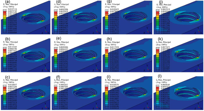
Figures 6 and 7 show the VMES and VMS distribution patterns along the trabecular bone-implant interface (bucco-lingual direction). In the upper part of the threads, higher values of VMES and VMS were observed in the peri-implant trabecular bone. In addition, VMES peaks were generally observed in the bone in the contact area with the double thread. On the other hand, Figs 10 and 11 show the distribution patterns of maximum and minimum principal stress in the trabecular bone. All simulated runs presented the highest values of maximum principal stress and of the minimum principal stress in the bone of the distal site. The maximum principal stress reached values between 1.66 and 3.17 MPa, while the minimum principal stress values were between −0.26 and −0.43 (Table 5).

Von Mises equivalent stress distribution patterns in the peri-implant trabecular bone. The letter corresponds with the experimental run.
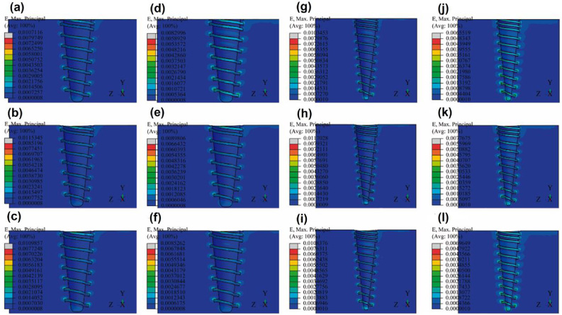
Von Mises strain distribution patterns in the peri-implant trabecular bone. The letter corresponds with the experimental run.
Load transfer from dental implants to peri-implant bone depends on several variables. The objective of this investigation was to evaluate the effect of diameter, length and elastic modulus in a new dental implant on the maximum VMES and VMS values of the peri-implant bone. In this study, the dental implants were statically loaded and simulated under immediate loading, incorporating a frictional contact area in the bone–implant interface.
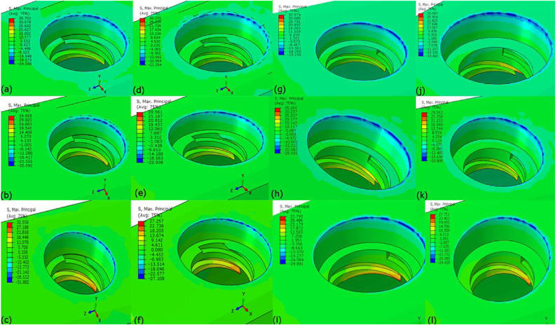
Maximum principal stress in the cortical bone. The letter corresponds with the experimental run.
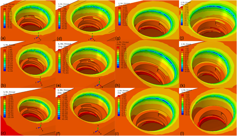
Minimum principal stress in the cortical bone. The letter corresponds with the experimental run.
The simulation results agree with other investigations by FEM [7,8,14,24], in the sense that the VMES are concentrated mainly in the peri-implant cortical bone, instead of doing it uniformly in all bone-implant interface. In several works, a high risk of bone resorption in the neck region of implants by using FEM [25] has been found. Furthermore, in all simulated conditions, the trabecular bone shows higher von Mises strain values than the cortical bone (Fig. 12b and d). This behavior is similar to that reported by Amid et al. [24] for tapered dental implants. However, in an investigation by Chou et al. [20], FEM overstrains were observed in the peri-implant cortical bone ridge in contact with the implant neck. In general, a decrease in the VMES and VMS values in the peri-implant cortical bone was observed in comparison with the results of FEA of other implant models. This behavior must be related to the inclusion of the double thread in the area near the neck of the new dental implant model.
In the twelve simulated runs, VMS values in the peri-implant bone were generally between 0.0002 and 0.003. In all cases, the maximum VMS values in the peri-implant cortical bone were between 0.0012 and 0.0017 (Fig. 3a, Table 3); while generally in peri-implant trabecular bone the maximum VMS values were between 0.0025 and 0.0038 (Fig. 7a, Table 4). However, at the interface of both bones, small areas with strain peaks were observed that reached values of 0.0085 (Fig. 5). In general, the VMS values generated by the twelve simulated runs must maintain or increase the peri-implant bone density [20].
Maximum and minimum principal stress in the peri-implant cortical and trabecular bone
Figures 12a and 12c show the effect of the three variables studied on the maximum VMES and VMS values in the peri-implant cortical bone. The three investigated variables (diameter, length, and elastic modulus in the dental implant) have a statistical significant influence on the maximum VMES and VMS levels in the peri-implant cortical bone. It was also determined that the interactions of the diameter of the implant with its length and its elastic modulus have a statistically significant influence on the VMES values in the peri-implant cortical bone. In addition, the interaction between the diameter and the length of the implant showed a statistically significant influence on VMS values.
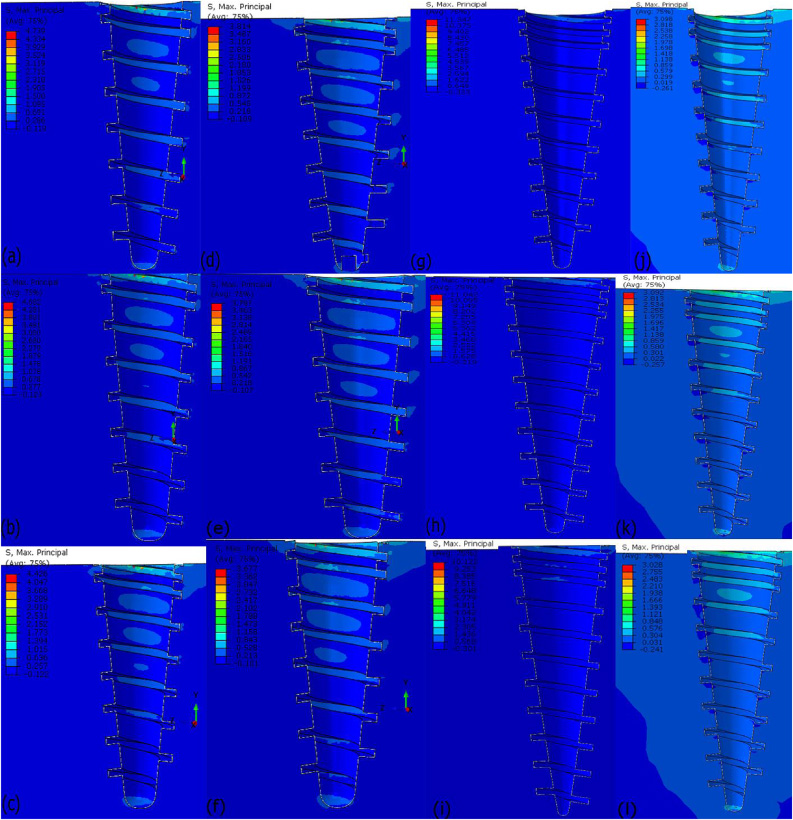
Maximum principal stress in the trabecular. The letter corresponds with the experimental run.
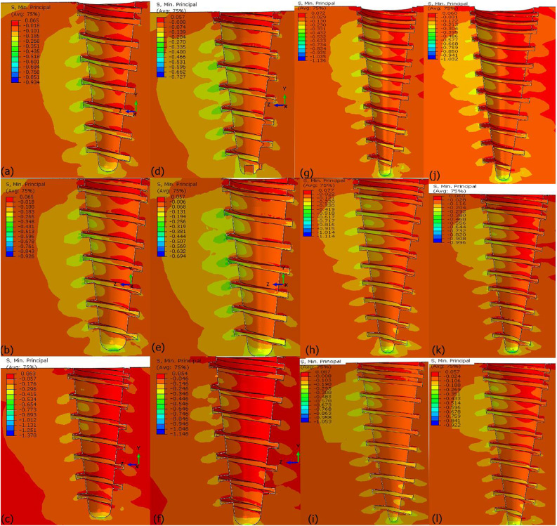
Minimum principal stress in the trabecular. The letter corresponds with the experimental run.
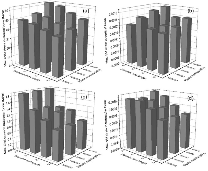
Effect of the diameter, length and elastic modulus of the dental implant in the maximum VMES values (A and B) and in the maximum von Misses strain values (C and D) in the peri-implant bone. Diameter (d) and length (l), I: d = 3.8 mm and l = 10 mm, II: d = 4.5 mm and l = 10 mm, III: d = 3.8 mm and l = 13 mm, IV: d = 4.5 mm and l = 13 mm.
In general, an increase in the values of the simulated variables produced a decrease of the VMES and VMS maximum values in the peri-implant cortical bone (Fig. 12a). The lowest values of these parameters were obtained by combining the largest diameter and length with the highest elastic modulus (Table 4). It was also found that the implant diameter has the largest influence on maximum VMES and VMS values in the peri-implant cortical bone in comparison to the rest of the studied variables. Increasing implant diameter had a very high influence on the decrease of the VMES and VMS values in the peri-implant cortical bone. However, the use of wide implants is limited for aesthetic requirements by the residual ridge width [25]. In addition, the use of wide diameter implants can cause bone loss in narrow posterior ridges [25]. According to other studies by FEM, increasing implant length had a moderate-to-large effect on reducing the stress and strain levels in the peri-implant cortical bone [3,26].
Figures 12b and 12d show the influence of the study variables on the maximum VMES values and the von Mises strain in the peri-implant trabecular bone. It was determined that only the diameter, length of the implant and its interaction have a statistically significant influence on both parameters. Additionally, it was found that the diameter of the implant showed the greatest influence on the maximum VMES and VMS values in the peri-implant trabecular bone. In summary, the levels of VMES and VMS in peri-implant trabecular bone were reduced when the implant’s diameter and length were increased.
Biological and clinical implications
In experimental studies, it is recognized that osseointegration and remodeling after implantation are related to the biomechanical responses of bone [29]. Stresses and/or strains in excess can cause bone loss, while low levels can reduce the peri-implant bone density. If the stress concentration in the peri-implant bone exceeds the physiological limits, the process of bone resorption will increase, leading to a high risk of bone loss [20,30]. This behavior is consistent with the results from in vitro and in vivo experiments and clinical studies, which demonstrated bone loss around the implant neck [31]. Furthermore, according to the reports of numerous works, overstrains in the peri-implant bone cause crack and bone failure [20]. On the other hand, long exposure of the peri-implant bone to a low strain level (<0.0002) causes a decrease in its density. Both situations can negatively influence the clinical success of dental implants.
The stress distribution patterns obtained showed moderately high values in the cortical bone around the implant neck. However, in none of the simulated experimental runs the strains exceed 0.004 in peri-implant bone, a value to which Duyck found marginal bone resorption [32]. In addition, in the peri-implant trabecular bone, the strains values were not less than 0.0006. These results allow us to predict a suitable biomechanical behavior of simulated dental implants. However, it is advisable to use the dental implant variants that have a greater length in implantation tests.
Conclusions
In this work, simulations of the biomechanical behavior of a new dental implant model under immediate loading using a 3D finite element analysis were carried out. The effect of implant diameter, length and elastic modulus of the dental implant on the maximum von Mises equivalent stress and von Mises strain in the peri-implant cortical and trabecular bone were evaluated. Within the limitations of this 3D FEA, the following conclusions can be drawn:
In general, the highest VMES values were observed in the peri-implant cortical bone. However, in this bone, both the maximum VMES values and the strain are similar or inferior to those reported in different studies of FE for other models of dental implants under immediate loading. Maximum VMS values were observed in peri-implant trabecular bone. However, generally in this bone strains levels were obtained that maintain bone density or increase it. The effect of the three simulated variables (implant diameter, length, and elastic modulus) and their interactions on the maximum VMES values and VMS in the peri-implant cortical bone can be summarized in: (a) Simulated variables have a statistically significant influence on the maximum VMES and in VMS values; (b) The interactions of the diameter of the implant with its length and its elastic modulus have a statistically significant influence on the VMES values; (c) The interaction between the diameter and the length of the implant has a significant influence on the maximum VMS values. The implant diameter, the implant length, and its interaction showed statistically significant influence on the maximum VMES values and the VMS in the peri-implant trabecular bone.
Conflict of interest
The authors have no conflict of interest to report.