
Abstract
BACKGROUND:
In some treatments using multiple dental implants, the implants are inserted in the bone with splinted or non-splinted implant prostheses. There are some reports about the influence of the splinted and non-splinted implants on stress distribution in the bone using the finite element method (FEM), and there is a controversy in the literature regarding whether the splinted or non-splinted implants prostheses reduce the stress generated on the implant-surrounding bone more efficiently. Additionally, the simple shape of the jaw bones with limited bone area was used for FEM analysis in many studies at the expense of accurate analysis.
OBJECTIVE:
The aim of this study was to evaluate the difference in stress distribution in the bone between the splinted and non-splinted implants, and between completely and partially edentulous mandibles.
METHODS:
The implants were inserted in the first premolar, second premolar, and first molar regions of the partial and complete mandibles, and the splinted and non-splinted crowns were attached to the implants. Vertical load (100 N) or oblique load (70 N, 30° from its long axis towards the lingual) was applied on the first premolar.
RESULTS:
When vertical load was applied to the partially edentulous mandible model, the stress was concentrated intensively on the cortical bone around the first premolar regardless of whether splinted or non-splinted implants were used. On the other hand, the vertical load applied to the completely edentulous mandible model caused the stress to be concentrated intensively on the cortical bone around the first premolar with non-splinted implants. With respect to the oblique load, the stress was concentrated intensively on the cortical bone around the first premolar only with the non-splinted implants, in both the partial and complete mandibles.
CONCLUSION:
This study shows the different stress distributions of the cortical bone around the implants between the partial and complete mandible. This indicates that the complete mandible should be used for the analysis of bone stress distribution around the implants using FEM.
Introduction
The use of dental implants has increased rapidly, and they can be used in partially or completely edentulous jaws with high success rates and viable applicability [1–3]. This treatment enables satisfactory mastication in patients and prevents bone resorption around the implants because of the transmission of the load from the implants to the jaw bone [4,5]. However, excessive load could be the main cause of bone resorption, because stress is directly transferred to the bone tissue during functional loading [6].
In some implant treatments, the implants are inserted with splinted or non-splinted implant prostheses [7]. The splinted implants can lead to better load distribution in the surrounding bone and increase the success rate of these treatments, because the applied load is directly transferred to the surrounding bone, and could lead to marginal bone loss in conditions of overloading. However, the splinted crowns can interfere with proper oral hygiene maintenance and complicate clinical and laboratory procedures [8].
A few studies have compared the biomechanical behaviour of the splinted and non-splinted implants [8–13]. Hasan et al. reported that the stress on the mandible decreased with splinted implants by using finite element method (FEM), and the values of stress reduction varied depending on the material of the crowns [9]. Toniollo et al. reported the mechanical effects of the splinted and non-splinted implant prostheses with 5 mm long implants by using FEM. According to the results, the maximum stress on the mandible decreased from 90 MPa to 70 MPa by using the splinted implant prostheses [10], whereas Meimandi et al. reported that the maximum stress on the mandible increased using the splinted implant prostheses [11]. There are some controversial results in the literature about the use of splinted and non-splinted implant prostheses reducing the stress generated on the implant-surrounding bone more efficiently.
Additionally, the simple shapes of mandibles that limit the bone area have been used for FEM in several studies at the expense of accurate analysis [12,13]. In several cases, the implants were inserted in a partially edentulous mandible, and the model was constrained at the bottom. These conditions differ from the conditions involving an actual mandible of a patient. The recent progress of computer and software performance enabled the creation of three-dimensional (3-D) models of the complications involved with an actual mandible from computed tomography (CT) images. There are some reports about stress analysis using the completely edentulous mandible model. Heo et al. reported about stress analysis using the completely edentulous mandible to analyse the effects of the splinted implant prosthesis [14]. However, comparison of stress distribution in the bone between the completely and partially edentulous mandibles has not been clarified.
In the present study, the mandible models were created from CT images and the stress distribution in these mandibles were evaluated for the splinted and non-splinted implant models.
Materials and methods
Preparation of models
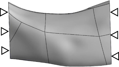
The complete mandible model was created from CT data of an anonymous patient, and was exported in the stereolithography (STL) format. It was converted to the computer aided design (CAD) format using reverse engineering software (Fig. 1). The first premolar, second premolar and first molar were extracted from the completely edentulous mandible model to create the partial mandible model (Fig. 2).

The computer aided design model of the complete mandible.

The computer aided design model of the partial mandible.
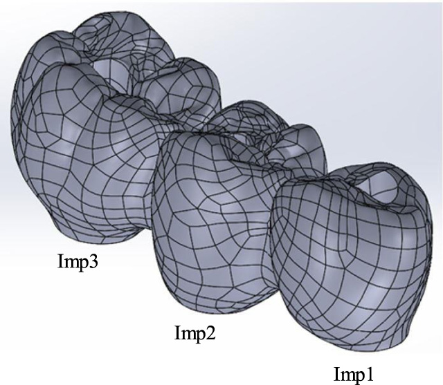
The geometry of the one-piece implant (4 mm in diameter, 18 mm in length) was reconstructed using the CAD software (Fig. 3), and models of the splinted and non-splinted crowns were created (Figs 4–5). The implants were inserted at the first premolar (Imp1), second premolar (Imp2), and first molar (Imp3) regions of the mandible, and the splinted and non-splinted crowns were attached on individual abutments. The material properties of each model were obtained from some papers, and are described in Table 1 [15–17].
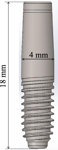
The one-piece implant model.

The computer aided design models of splinted crowns.
The computer aided design model of non-splinted crown.
Eight types of simulation models are shown in Table 2, and the stress distribution of each model was evaluated by a linear elastic finite element analysis. Vertical load (100 N) or oblique load (70 N, 30° from its long axis towards the lingual) was applied on the Imp1 (Fig. 6) [11,18]. The complete mandible was fixed in all directions in the areas corresponding to posterior condyle and angle of the mandible (Fig. 7). The partial mandible model was restricted on the both sides as indicated in Fig. 8. The contacts between the implants, crowns, and surrounding bone were assumed to be perfectly bounded. The complete mandible models were composed of 1,090,648–1,584,564 elements, while the partial mandible models were composed of 467,444–522,737 elements. Different stress outputs, such as Von Mises stress and maximum and minimum principal stresses, are generally used to better understand biomechanical behavior of materials. The Von Mises stress is also used as an indicator of the average stress level at the peri-implant region, providing a global measure for the load transfer mechanisms because the Von Mises stress is expressed as one scalar stress which facilitate the intuitive comparison of stresses concentration [4–6,8,9,11,12,14,19]. The highest Von Mises stresses during occlusal loading are encountered in the bone surrounding the implants. In the present study, the average of Von Mises stress values on the surface of the cortical bone around the body of the implant, and the stress distribution in the cortical bone around the implants were evaluated.
Material properties
Material properties
Simulation models in this study
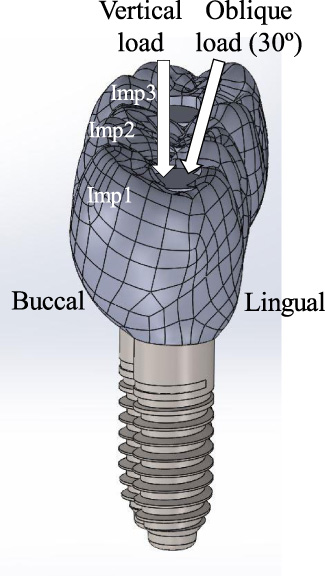
The schematic drawing of the applied load condition.
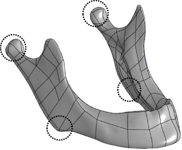
The fixed area of the complete mandible model (circle).
The fixed area of the partial mandible model (triangles).
Vertical load
The Von Mises stress distribution in the longitudinal cross-section of the partial mandible with splinted and non-splinted implants, subjected to a vertical load from the buccal side (models A and B), is shown in Fig. 9 and 10, respectively. The stress distributions of the complete mandible with the splinted and non-splinted implants are shown in Fig. 11 and 12, respectively (models E and F).
The stress distribution in model A (partial mandible, splinted implants, vertical load).
The stress distribution in model B (partial mandible, non-splinted implants, vertical load).
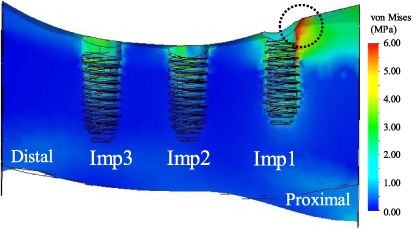
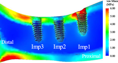
The stress distribution in model E (complete mandible, splinted implants, vertical load).
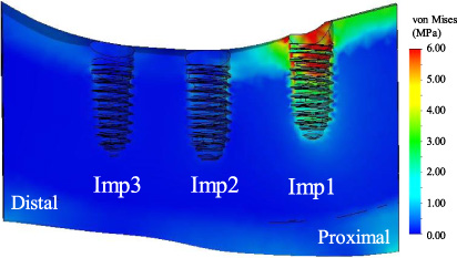
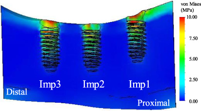
The stress distribution in model F (complete mandible, non-splinted implants, vertical load).
Comparing the stress distribution between the splinted and non-splinted implants in the partial mandible, the stress on the cortical bone around the Imp1 was concentrated on the right side of Imp1 in model A as seen in Fig. 9 (see circle). On the other hand, the stress around the Imp1 was concentrated on the entire circumference of Imp1 in the model B as seen in Fig. 10. The same tendency was observed between models E and F in the complete mandible (Figs 11 and 12). The Imp1 was pressed vertically in models B and F because the Imp1 was independently inserted in the mandible, and the stress concentrated on the entire circumference of Imp1. On the other hand, all three implants could be regarded as one unit in models A and E, because they were connected by a splinted crown. The crown could rotate to the right on Imp1 when the vertical load was applied to it, leading to compression of the cortical bone on the right side of Imp1 and concentration of the stress in this area.
Figure 13 shows the means of the Von Mises stress values on the cortical bone around the body of the implants indicated in Figs 9–12. Comparing models A and B of the partial mandibles, the difference in the stress values between Imp1 and Imp2 and between Imp1 and Imp3 in model A was lower than that in model B. This can be explained by the effect of the splinted implants. The load applied on Imp1 was transferred to Imp2 and Imp3 through the crown in model A. This effect of the splinted implants in this study corroborates with other studies [9,20]. Batista et al. reported the evaluation of the mechanical effect of the splinted and non-splinted implants by FEM [20]. Three implants were inserted in the model of the partial maxillary posterior region (from first premolar to first molar), and a vertical load of 400 N was applied on each implant. According to the result, the stress on the implant inserted in the first molar region was larger than that in the first and second premolar in the non-splinted implants model, whereas the stresses on these three implants were almost the same in the splinted implants model. This indicated that the stress generated in the splinted implants could be equally distributed to the three implants through the splinted crown.
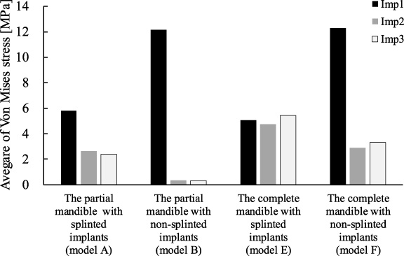
The average of Von Mises stress values in models A, B, E, and F under vertical load.
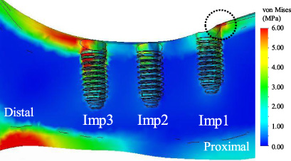
Comparing models E and F in the complete mandibles, the stress on Imp1 was highest among the three implants in model F, whereas the stresses on the three implants were almost the same in model E due to the aforementioned effect of the splinted implants. However, this was different in the case of the partial mandible (models A and B), where the stress tended to concentrate intensively on Imp1 irrespective of splinted or non-splinted implants used. This is because there were differences in the constrained areas between the partial and complete mandibles. Figure 14 shows the stress distribution of the model E. The geometry of the area of the mandible (see circled area) was similar to an L-shape. Generally, the stress was concentrated at the vertex of the L-shaped beam as well as the loaded point, when the vertical load was applied to one side of the beam [21]. Therefore, the stress could be concentrated in the circled area of the mandible (Fig. 14). This stress would increase the stress of the cortical bone of the complete mandible around Imp2 and Imp3, irrespective of the use of splinted or non-splinted implants. On the other hand, the partial mandible was constrained on both sides of the model as indicated in (Fig. 8 (see triangles). This geometry was similar to a beam, and the stress was concentrated only on the loaded point [22].
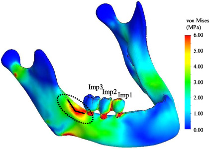
The stress distribution of the whole mandible in model E.
These results show that the splinted crown contributes to transferring the load to adjacent implants. However, the addition of the stress from the vertex of the L-shape beam to the cortical bone around Imp2 and Imp3, as seen in the complete mandible, was not observed in the partial mandible model.
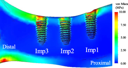
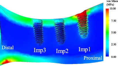
The Von Mises stress distributions in the longitudinal cross-section of the partial mandible with splinted and non-splinted implants subjected to oblique load from the buccal side is shown in Fig. 15 and 16, respectively (model C and D). The stress distributions of the complete mandible with splinted implants and non-splinted implants are shown in Fig. 17 and 18, respectively (model G and H). From these stress distributions, the means of the Von Mises stress values on the circumference of the cortical bone around the body of the implants were obtained (Fig. 19).
The stress distribution in model C (partial mandible, splinted implants, oblique load).

The stress distribution in model D (partial mandible, non-splinted implants, oblique load).
The stress distribution in model G (complete mandible, splinted implants, oblique load).
The stress distribution in model H (complete mandible, non-splinted implants, oblique load).
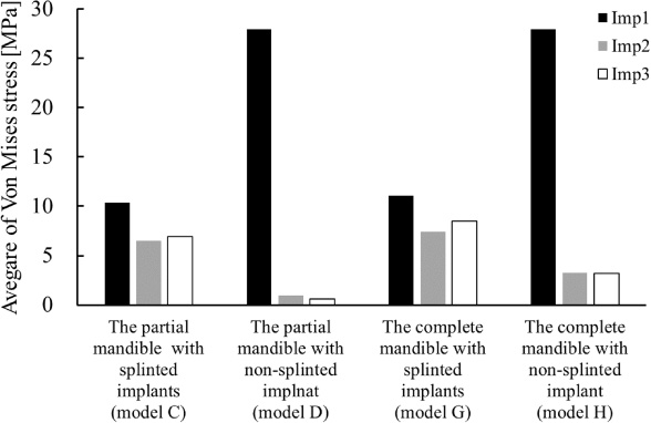
The average of Von Mises stress values in models C, D, G, and H under oblique load.
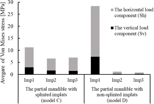
The sum of stress values generated by the vertical and horizontal load components (model C and D).
With respect to models C and D in the partial mandibles, the stress on Imp1was highest among the three implants in model D, whereas the stresses were almost same on all implants in model C. Despite the same partial mandible with splinted implants, the stress balance seen in model C differed from that of model A (Figs 13 and 19), with the stress on Imp1 being the highest among the three implants in model A. This indicated that the stress balance among the implants (Imp1, Imp2 and Imp3) in the partial mandible differed with the vertical and oblique load, because the horizontal load component of the oblique load significantly influenced the total stress value. The oblique load (70 N) could be resolved into the vertical load component (60.6 N) and horizontal load component (35.0 N). The sum of the stresses generated from the vertical and horizontal load component would almost be the same as the stress generated by the oblique load. Figure 20 shows the stresses generated from the vertical and horizontal load component presented as Sv and Sh, respectively, in models C and D, and reveals that the Sh was much higher than Sv in both models. The large Sh stress influences the total stress, regardless of the amount of Sv stress. Marcian et al. reported that horizontal load (150 N) on the implant caused high strain intensities that exceeded the bone fracture limit, whereas the vertical load (150 N) did not result in non-critical strain values. This also implies that the horizontal load generated larger stress on the bone than the vertical load. The lateral sides of the cortical bone of the mandible can be more easily deformed than the upper cortical bone, because the shape of the cross-section of the mandible bone is similar to a vertical eclipse [23]. The ratio of the Sh and Sv stress on the bone around Imp3 to Imp1 in model D was 4.8% and 6.5%, respectively (Fig. 20). The amount of transferred stress to Imp3 in model D was less than 10% in both the vertical and horizontal load components. On the other hand, the ratios of the Sh and Sv stress on the bone around Imp3 to Imp1 in model C were 68.4% and 28.6%, respectively (Fig. 20). The ratio of Sh stress (68.4%) in model C was much higher than that in the model D (4.8%). In model C, the Imp2 and Imp3 could have been subjected to a torque through the splinted crowns from the horizontal load component on Imp1. The stress generated from the horizontal load component on the cortical bone around Imp2 and Imp3 was much larger than that generated from the vertical load component, because the lateral sides of the mandible around Imp2 and Imp3 could be more easily deformed than the upper surface of the mandible. Therefore, large amounts of transferred stress around Imp2 and Imp3 generated from the horizontal load component could increase the total stress around Imp2 and Imp3, and the effect could lead to the almost same stress balance on three implants as in model C. One-piece implants were used as the implant model in this study. However, different results could be derived in the case of two-piece implants. The stress generated from the horizontal load would be lesser with two-piece implants than one-piece implants, because the horizontal load would be absorbed at the joint of the abutment and implant due to the existence of the micro-gap between the abutment and implant [24]. Wu et al. reported that the stress on the cortical bone around the two-piece implant subjected to the oblique load was lesser than that around the one-piece implant due to the absorption of the horizontal load component in the former [25].
Comparing models C and G using the splinted implants, the ratios of the Sv and Sh stress on the bone around the Imp3 to Imp1 were 94.5% and 61.5 % in model G, respectively (Fig. 21). The ratio of the Sv stress in the model G (94.5%) was much higher than that in model C (28.6%) despite using the same splinted implants. This could be attributed to the stress from the vertex of the L-shape of the mandible that added to the stress around Imp3 in the complete mandible (model G) as described in Section 3.1.
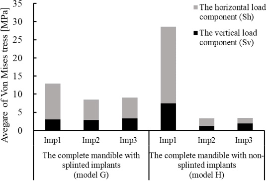
The sum of stress values generated by the vertical and horizontal load components (model G and H).
It is observed from these results that the horizontal load component of the oblique load has a significant influence on the total stress. Furthermore, the large stress generated from the horizontal load component changed the stress balance between the three implants in the partial mandible subjected to the oblique load (model C), as compared to the stress balance in the partial mandible subjected to the vertical load (model A).
In the partial mandible model subjected to the vertical load, the stress was concentrated on the cortical bone around the first premolar regardless of whether the splinted or non-splinted implants were used. In the complete mandible model subjected to the vertical load, the stress was concentrated intensively on the cortical bone around the first premolar with non-splinted implants. With respect to oblique load, the stress was concentrated intensively on the cortical bone around the first premolar, in both the partial and complete mandibles, only with the non-splinted implants.
Footnotes
Acknowledgements
We would like to thank S. Fujikawa of E-joint Co., Ltd. for the 3-D model of the crown data, and T. Kumagai of Yamahachi Dental MFG for stimulating discussions.