
Abstract
Logic Programming is a programming paradigm widely used for teaching Artificial Intelligence in university courses. Prolog, probably the most popular Logic Programming language, is based on inferences similar to theorem provers, and learning it is propaedeutical for understanding formal specification languages.
However, after a first phase in which students learn how specifications can be translated into executable code, a second phase is necessary for engineering the resulting program. In this second phase, having a clear picture of the execution model is crucial.
In this paper, SLDNF-Draw, a program that visualizes the SLDNF operational semantics of
Prolog, is presented. SLDNF-Draw produces trees in L
SLDNF Draw is completely written in Prolog, as a meta-interpreter, and does not rely on external imperative languages for the visualization.
Introduction
Logic programming languages are one of the most successful examples of declarative languages; they have a formal declarative semantics, as well as sound and complete corresponding operational semantics. They have a notable number of practical applications, are widely used in Artificial Intelligence, and are often used in university courses as a valid tool to support learning of AI techniques [12].
In fact, many applications in AI represent the knowledge of the system in logics, and tree-search is widely used to find a solution. Logic programming languages provide efficient tree-search algorithms, and have transparent backtracking mechanisms. The most popular logic programming language is probably Prolog. In Prolog the user is not required to adopt the predefined search method, nor to blindly accept the other engineered choices adopted by the language developers: Logic Programming lets the user easily redefine the interpreter by means of meta-interpretation. Practical applications range from solving combinatorial problems (for instance, Constraint Logic Programming is one of Logic Programming ribs and is effectively used by various companies, like British Airways, Cisco Systems, Airfrance, just to name a few) to formal verification of security protocols [3–5, 10].
However, learning Logic Programming requires a change in the approach to programming: while in imperative programming the focus is on algorithms (Algorithms + Data Structures = Programs [28]), in logic programming the control is intrinsically embedded in the language, and the programmer has only to formally state the logics of the program (Algorithm = Logic + Control [18]). Thus, algorithms become less important (at least at a first view), while giving correct specifications becomes crucial. This is exactly the goal of rapid prototyping: make specification and implementation (almost)coincide.
At a second view, however, the program must often be engineered, and be written taking into account the underlying algorithm adopted by the resolution engine, in order to avoid infinite loops, or frustrating inefficiencies. The reason is that Prolog is not a theorem prover. A theorem prover must find a solution (if it exists) at all costs, while Prolog is a Turing-complete programming language that should let the user define efficient programs. For example, Prolog skips the inefficient breadth-first search strategy, and prefers an incomplete but fast depth-first searchstrategy.
The story is not new: students have to face and learn the engineering art of choosing the right trade-off, and exploit the available tools at their full capabilities.
The problem in teaching logic programming to engineering students is that they often adopt an imperative viewpoint; they are usually very skilled in writing programs in C, or C++, or Java. Thus, they often start imagining the operational behavior when they write a program, without thinking very much about the logic behind it. They become quite skilled in optimizing logic programs, before fully understanding the logic programming style itself.
For instance, typically students think that the clause should be uniquely identified, and not simply non-deterministically selected. Thus they often ask the teacher if there is a language statement, or instruction, that the programmer should use to identify the intended clause. The answer is twofold. In a first phase, the professor should convince the students that such a syntactic item is not necessary for a correct specification of the program. In a second phase, the available syntactic tools (like mode declarations, indexing, and even the cut) can be described, in order to improve the efficiency.
The learning process can be seen composed of two steps: learning to program in logics, forgetting
about algorithms figuring out the
algorithm that has been developed, and improving it.
Hermenegildo [21] has a similar viewpoint, and suggested to use in the first step a logic language with a complete search strategy, and to introduce standard Prolog, with its efficiency issues, in a second phase.
Learning, in both of the two phases, relies on a good understanding of the operational semantics. The usual operational semantics in Prolog is SLDNF-resolution [7], i.e., SLD (Selected Literal Definite clause) resolution together with Negation as Failure. In SLD resolution every state in the computation is a node of a tree; the tree will be typically explored by depth-first search with backtracking. It is important, for students, to visualise such trees, understand which clauses will be selected, which will be cut. The Prolog tracer could be used, but its use is indeed limited for learning purposes.
Teachers need to show examples of SLDNF trees in handouts, written material and presentations. However, drawing SLDNF trees with usual word processors or presentation software is a long and tedious operation, beside being highly error-prone. Current tools that show SLD trees usually assume that the user interacts directly with the tool, that can scroll large windows back and forth to compare different parts of a tree. This makes such tools difficult to use for developing handouts for the students, and they are difficult to use inside presentations, in particular with animations that show incrementally how the tree is explored. Of course, the teacher can use such tools giving a sort of demo, but the generated trees are not meant to fit well inside written documents and presentations. Also, the language is usually a restricted subset of Prolog. Often there is no treatment of negation, of the cut, or of Prolog built-in predicates.
This paper describes a tool that a visualization of SLDNF trees in files that can be easily
included into written documents and presentations. The tool, called SLDNF Draw, produces in
output a L
The rest of the paper is organized as follows. First the specifications and features of SLDNF Draw are given in Section 2. Some Prolog exercises that have been proposed to students and visualized through SLDNF Draw are in Section 3. Related work is described (Section 4). Conclusions and possible directions for future work follow.
SLDNF Draw
SLDNF Draw [13] is a program that visualises SLDNF trees given a knowledge base and a goal.
The devised architecture is depicted in Fig. 1. After loading SLDNF Draw, the user consults a logic program and provides a
query. A file

Architecture.
In the following, we define the structure and requirements taken into consideration in the development of SLDNF Draw.
SLDNF Draw is a visualization software entirely written in Prolog. It is a meta-interpreter, i.e., a Prolog interpreter written in Prolog. The simplest Prolog meta-interpreter consists only of just three lines of code [9]:
Executing vanilla (G), where G is a Prolog goal, produces the same replies that a Prolog interpreter would provide. Such simple meta-interpreter is almost useless as it is, since it barely executes a Prolog program introducing some overhead. Its usefulness stands in the fact that it follows strictly the steps that a Prolog interpreter executes, and it is can be easily extended to provide further features. SLDNF Draw extends the vanilla meta-interpreter and saves the necessary information to visualize the SLDNF tree onto a file.
A sketch of the core structure of SLDNF Draw is shown in Listing 1. The interpreter in Listing 1 assumes that the output is passed to some
software for visualization of graphs, such as GraphViz [11]. Predicates
Sketch of meta-interpreter that saves an SLD tree
Sketch of meta-interpreter that saves an SLD tree
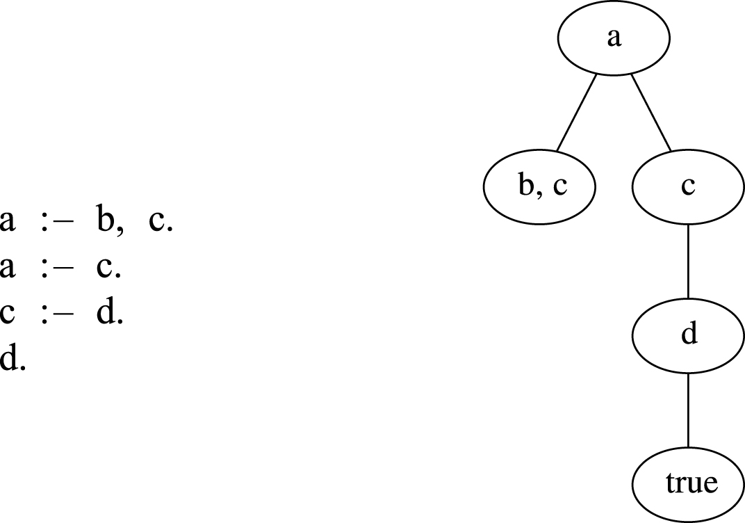
A simple Prolog program and a corresponding SLD tree plotted with GraphViz.
SLDNF Draw is completely written in Prolog, thus no knowledge of imperative or object-oriented languages is required neither to use it, nor to understand and modify its code. This is an important feature for a software that aims at fostering the knowledge of logic programming; also, it provides an interesting example of Prolog program to be proposed to students.
It was developed for ECL i PS e [22], but it could be ported to other Prolog dialects and implementations.
Prolog is sometimes defined as SLD Resolution plus Negation as Failure. Actually,
Prolog is a full programming language with built-ins that can handle mathematics (the
Cut
One of the difficult concepts for students to understand is the cut
symbol (written “!”). This extra-logic predicate operationally removes some branches of
the SLDNF tree. Of course, cuts should be used as rarely as possible. The trend is to
exclude the cut from new logic programming languages (even very efficient ones, like
Mercury [23]), and to prefer operators having
a similar operational semantics but a more understandable behaviour (like, for example,
the
However, the cut is still part of ISO Prolog and of almost all Prolog implementations. The cut is still widely used in Prolog programming, so understanding it is important in order to understand software written by others, and can be also useful to engineer and profile the execution of a program.
For these reasons, it is important that students understand the operational semantics of cut, and visualise the nodes that will be explored and the ones that will be not.
Output
In order to be useful, the output format should be easy to visualize, and to zoom in case of large trees. It is desirable for the output format to be understandable and easy to convert to other graphic formats.
L
L
SLDNF Draw lets one create trees that can be animated, to show incrementally the
construction of the tree (see for example Fig. 3). The typographic quality is that of L
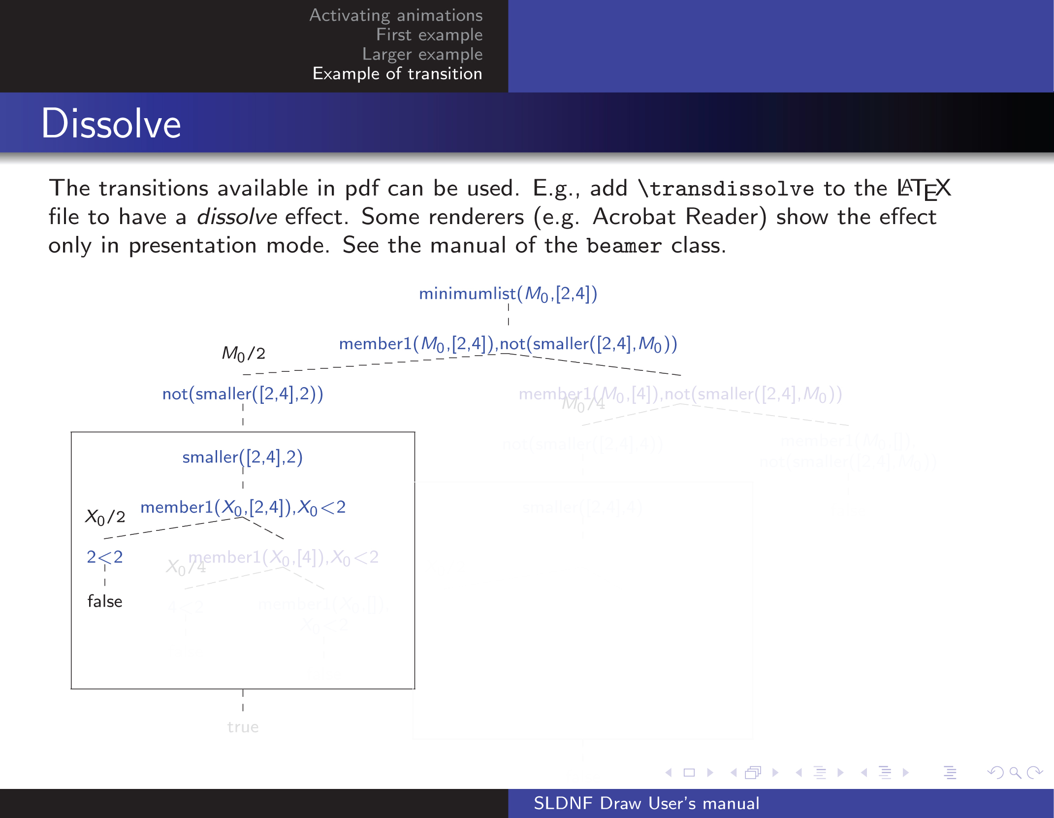
A presentation in which an SLDNF tree is shown through animations, showing only part of the tree.
A number of customizations are available, as Prolog or L
A set of exercises are prepared for the students. Teachers provide the knowledge base (the Prolog program) and ask the students to visualise the corresponding SLDNF tree. Then, students are asked to comment on the result: whether the program is correct, how to correct it if it is not, suggest improvements if it could be made more efficient, and so on. Some of the proposed exercises are shown in the rest of this section.
Reversibility
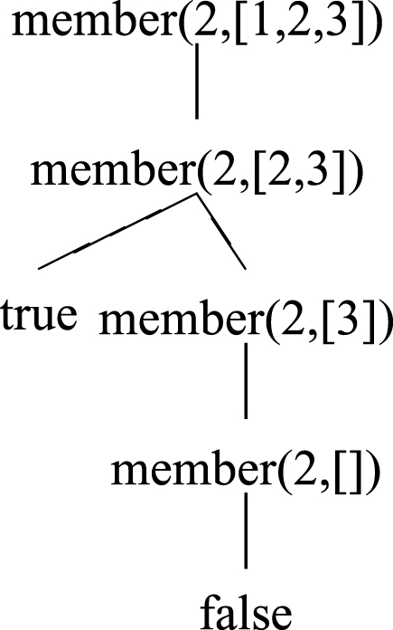
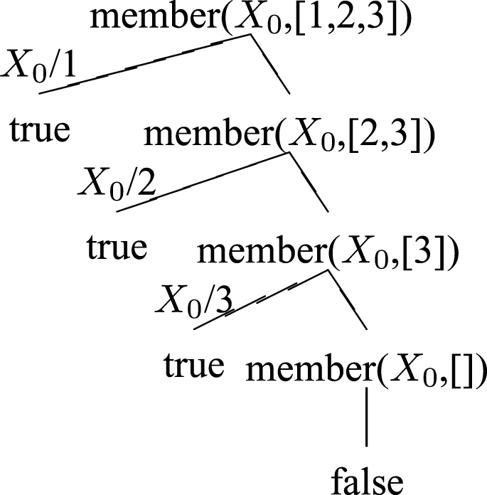
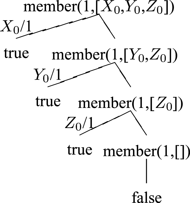
One of the first examples in many Prolog courses is about the
can be obviously used to check if an element belongs to a list (Fig. 4), but can also be used to generate assignments (Fig. 5) for a variable (useful, for example, for implementing a generate-and-test pattern) or even for generating the elements of a list, or using lists as approximation of sets [20] (Fig. 6).
Most Prolog compilers are able to optimize tail-recursive predicates, with the so called
last call optimization. In this case, the SLD tree shows the difference
between a naively written predicate, like the following, that computes the length of a
list (Fig. 7):
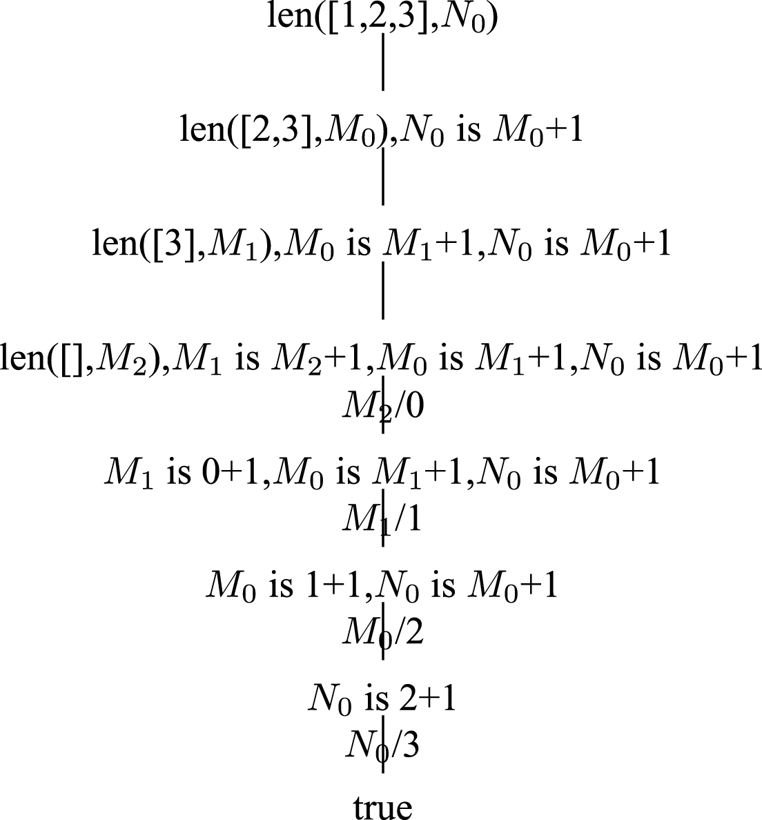
Length of a list.
and its tail recursive version (Fig. 8):
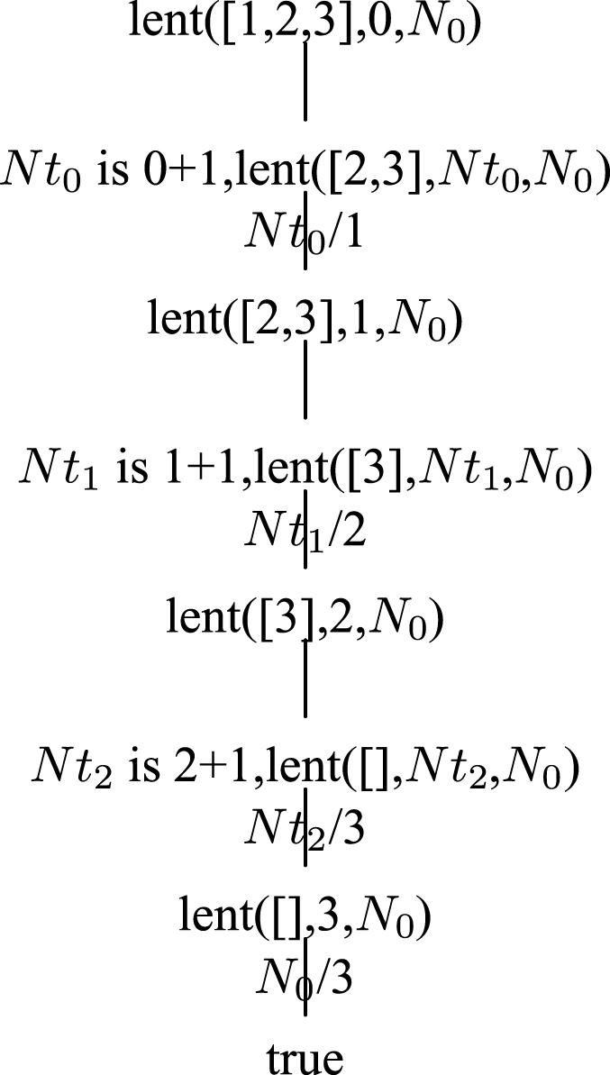
Length of a list: tail recursive implementation
The differences are evident, and it is easy to convince students that the first implementation takes more memory by simply looking at the shapes of the trees: of course, the resolvent must be kept in memory in order to execute the program. Also, the resolvent shows the typical evolution of the stack in a recursive call: first all the activations are pushed in the stack, then the end condition is reached and the activation records are popped out; so the tree has a diamond-like shape (Fig. 7). The tail-recursive implementation, instead, needs a constant number of activation records, so the length of the resolvent is almost constant.
The cut is always difficult to understand fully, and even expert Prolog programmers can
make mistakes. One of the proposed exercises gives this definition of the minimum of two
numbers:
Such a definition seems perfectly reasonable at a first sight: the minimum is A if A < B and it is B otherwise. However, the SLD tree shows very clearly that the answers can be unsound: in Fig. 9, the first tree shows how the answer to the question “what is the minimum between 1 and 2” is computed: there exists only one computed answer, which is 1. In the second tree of Fig. 9, instead, the question is “is 2 the minimum between 1 and 2?”, and the answer, surprisingly, is yes.

Two invocations of the minimum predicate with cut give different (unsound) results.
When facing this program, students are able to find a correct implementation of the
Both ideas are correct; students should be encouraged to propose alternative solutions, and select their preferred one, knowing the pros and cons of the various implementations. Figure 11 shows the SLD tree of the correct version.

The SLD trees of the correct version of the minimum predicate.

Minimum of a list: implementation based on the definition.
In some cases the specifications of the program coincide exactly with the definition
given in mathematics. Consider, for example, the minimum of a list. The definition
proposed to students in mathematics courses is the following: an element is the minimum of
a set if it belongs to the set and there is no such element belonging to the set which is
smaller.
The specifications are already executable:
If the specifications are correct, the program is already correct; logics supports rapid prototyping. On the other hand, the execution model can be inefficient, as can be seen from the SLDNF tree (Fig. 10).
Vast parts of the tree are evidently repeated, so one may think to optimise it by cutting some branches. Since the minimum value is unique, one can stop the search as soon as the minimum is found. Students are usually very keen in understanding which branches can be cut, and where the cut can be put in order not to change the semantics of the program (Fig. 12).

Minimum of a list: implementation based on the definition, cutting redundant branches.
As a second step, if the efficiency requirements are tight, it can be implemented with
tail recursion, but this typically means figuring out an algorithm, not simply
implementing specifications (Fig. 13).

Minimum of a list: tail recursive version.
Another option would be to use tabling, a feature available in many Prolog languages, which, however, does not rely on the classical SLDNF resolution but on the extension called SLG resolution [6]. As the name implies, SLDNF Draw does not currently deal with SLG resolution, although it would be an interesting extension.
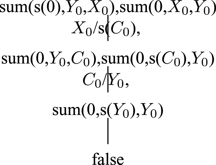
Integer numbers can be defined in the very same way the students are taught in mathematics courses, i.e., from Peano axioms: an integer number is either zero (0) or a successor (s) of an integer number. Basic operations can be defined easily; for example the rules for the sum can be encoded with two clauses, the first saying that X + 0 = X and the second declaring that s (A) + B = s (C) whenever it is known thatA + B = C:
Given such a definition, simple equations can be solved, as conjunction of goals. For
example,
However, the interpreter can give wrong results if the occur-check is turned off, as the following example shows (Fig. 14):
Seeing this example, students have different viewpoints: either they think that the result is infinite, or they think that the result is wrong (as a number cannot be equal to its successor). It is worth to let students discuss in brainstorming sessions or in small groups if the provided result is correct. Finally, the professor explains the occur-check: the interpreter can check that all the generated data structures will be acyclic before performing unification. Of course, this has a cost, so the user is warned. The occur-check can be switched on, and a correct result is provided (Fig. 15).

Equation solution without occurs check.
Equation solution with occurs check.
SLDNF Draw is a meta-interpreter that reuses the same implementation of unification of Prolog, so it is enough to switch on the occur-check in the host interpreter to have SLDNF Draw produce SLDNF trees with the occur-check. Other extensions of the unification algorithm are immediately utilized by SLDNF Draw; for example, many Prolog systems let one customize the unification algorithm through attributed variables [16].
Although Prolog programs are often based on lists, Prolog also has arrays, that can be extremely useful when engineering and optimising programs. In fact, all Prolog data structures are based on terms, that are built with a functor and a sequence of terms that are accessible in constant time. Thus, a term like a (X, Y, Z) can be seen as an array containing three variables. An array can be generated with the built-in predicate functor/3; for example the previous array is generated with the goal functor (A, a, 3). The elements of the array can then be accessed through unification: for example, to access the second element the unification A = a (_ , K, _) can be used. However, arrays should also let the user access the n-th element for any computed n, not just for numbers predefined at compile time. For this reason, Prolog contains the built-in arg/3 predicate, that can be used to access the single elements in constant time, as shown in the following example:
The code is quite self-explanatory: the predicate creates an array containing the natural
numbers from 1 to N - 1. Note how the SLDNF tree in Fig. 16 shows the array being filled with values: the
variables occurring in the term a (X0,
X1, X2) in

Example with arrays.
Other tools are available on the web for drawing SLD trees; some of them are reviewed in the following.
PrettyProlog [24] is an interpreter for Prolog
written in Java, born for didactic use, supporting list management, cut, negation as failure
and meta-programming. It has a GUI showing the stack of the interpreter and the SLD tree.
The version published in [24] does not support
built-in predicates, such as the
SLD Draw [15] draws on-screen the SLD tree of a goal. The source code is not provided; it does not handle negation, although it can show the cut. However, a good understanding of negation is fundamental in logic programming, so using a standard representation of negation in SLDNF trees is important for students. Moreover, having available the source code is useful in order to understand how the program works.
CI Space [8] is a set of tools for learning computational intelligence. Among others, it contains a Java applet for drawing SLD trees. It has a limited support for negation and no support for built-ins.
Prolog Visualizer [19] shows the execution of a Prolog program incrementally. It shows the phases of selection of a clause, unification, and returned binding. It also shows the corresponding SLD tree. However, it does handle numbers, the built-in predicates (for example, the ones for dealing with arithmetics), the cut, nor negation.
Showing the behaviour of the full Prolog language is important. As noted by Ducassé [21], especially for students who are not seeking academic careers, Prolog is viewed as a toy language (too small and too simple) and is not appreciated as as a real programming language. So, focusing only on SLD resolution with Negation as Failure without considering the built-ins could be too restrictive. Built-ins are important to show the full capabilities of Prolog. In particular, engineering students should know the built-ins that can improve efficiency: e.g., handling arithmetics is a must, and arrays are very useful. A didactic program should show how these built-in predicates behave, and how they interact with the other predicates. Stated otherwise, a visualisation program should show the trees for a full Prolog syntax, not just limit itself to SLD resolution.
Concerning the visualization of logic programming execution, some important work has been done in the context of Constraint Handling Rules (CHR). Abdennadher and Saft [1] developed VisualCHR, a visualization tool to show the propagation of CHR constraints. VisualCHR is written in Java, and relies on a Java implementation of the CHR engine; the CHR compiler had to be modified in order to accommodate the visualization. In order to extend VisualCHR also for CHR implementations developed on top or Prolog, Abdennadher and Sharaf [2] propose a source-to-source transformation that avoids the modification of the CHR compiler. SLDNF Draw does not need a source-to-source transformation because it relies on a meta-interpreter. Differently from imperative and object oriented languages, writing a Prolog interpreter in Prolog is extremely easy, and consists of only three lines of Prolog code. Such a simple interpreter can then be modified to support the visualization of the execution as a tree.
Finally, although they do not show SLD trees, many Prolog systems have visual interfaces for debugging, that are useful also for learning the mechanisms used by a Prolog interpreter. A very appealing one is included in SWI Prolog [27], with a particularly nice graph representation of the call stack.
Conclusion
This work presented SLDNF Draw, a program that draws the operational semantics of Prolog. It is developed as a meta-interpreter, and it is available for the students to look at its source code. It can be freely downloaded from [13]
It has been used in university courses for teaching logic programming and, in particular, the features of Prolog. SLDNF Draw handles the full syntax of Prolog, it is not restricted to SLD resolution, but can handle negation, cut, built-in predicates (like arithmetic or aggregation predicates), which are necessary in real-life applications.
The output of SLDNF Draw is a tree in L
SLDNF Draw is implemented as a Prolog meta-interpreter, which makes it available for a wide variety of platforms and operative systems. The first versions of SLDNF Draw use only ISO-Prolog features, and thus can run on any Prolog supporting the ISO standard. The last versions use some features specific of ECL i PS e Prolog [22] for the representation of the variable bindings, but earlier versions (with less features) are still available for download on the web page [13].
In our experience, students find the program useful to understand the operational semantics of Prolog: they use it for making experiments, for understanding which implementations are more efficient, and for visualising the Prolog execution.
Possible future extensions include extending the software to show also SLG trees (or forests) [6], since SLG resolution can be considered as an extension of SLDNF resolution, and include constraint propagation and branch-and-bound (in order to visualise Constraint Logic Programming [17] derivations). A further extension could be to integrate SLDNF Draw into a web application, for example in a front-end for Prolog such as SWISH [26].