



Abstract
Background:
Within GRIP, ESD (Energy Saving Device(s)) are installed on existing vessels. Installation of an ESD can influence the neighbouring hull outfitting elements.
Objectives:
The influence of ESD installation on the hull outfitting elements have been investigated.
Methods:
The classification rules have been studied to identify all parameters and subjects that could be influenced by installation of an ESD.
A selection of subjects is further investigated to provide an estimation of the magnitude of the impact.
Five example ESD’s have been investigated. The influence on the neighbouring hull outfitting elements has been determined by comparison of results of hydrodynamic calculations without and with an ESD.
For two cases, the effect on propeller cavitation behaviour has been investigated.
Results:
The possible effects of an ESD on the requirements according class rules (overview table).
For selected subjects, the magnitude of influence is defined in relation to the change of a directly influenced parameter.
For the example cases, the influence on the neighbouring hull outfitting elements and on propeller cavitation behaviour has been reported.
Conclusions:
Installation of an ESD affects indeed the neighbouring hull outfitting elements and their compliance with class rules in certain cases. The possible effects of an ESD on the compliance to class rules requirements are summarized in Table 1. Most significant impact can be expected for up-stream installed ESD and ESD directly mounted on the propeller. The addition of an ESD to a propeller has a linear influence on torsional frequency and stress as well as whirling frequency, bearing load and mis-alignment. Adding 10% MOI (of total propeller MOI) results in 3% decrease of torsional frequency, 10% increase of torsional stress, decrease of 2.5% of natural critical whirling speed. Addition of 10% mass results in a decrease of 1.7% of critical whirling speed. The influence of an ESD on alignment are shown in Table 3.
Introduction
Within the framework of the GRIP project, ESD (Energy Saving Device(s)) are installed on existing vessels. The neighbouring hull outfitting elements can be influenced by the installation of an ESD, due to change in hydrodynamic flow, added mass or other changes.
Within task 3.4 of the GRIP project, the influence on the main hull outfitting elements has been investigated. The following approach has been applied for this investigation:
Study of classification rules
Estimation of magnitude of influence
Analysis of example application cases
A detailed description of the work performed and the achieved results is presented in the sections hereafter.
Study of classification rules
The classification rules for the hull outfitting elements have been studied to identify all parameters and subjects that could be influenced due to application of an ESD. This study has been performed, focusing on the classification rules for structural design of the main hull outfitting elements of the most occurring classification societies: DNV, BV, ABS, LR and GL.
Scope
The classification rules for propellers, propulsion shafting, bearings and bearing brackets, rudder and stern tubes have been studied for the following class societies:
Lloyd’s Register (LR)
American Bureau of Shipping (ABS)
Det Norske Veritas (DNV)
Bureau Veritas (BV)
Germanischer Lloyd’s (GL)
The general rules for classification of ships have been studied. Rules for ice class have not been included in this study.
The classification rules have been studied focusing on the propeller, shaft line, bearings and bearing brackets, rudder and stern tubes. A complete overview of the studied subjects is given in Table 1.
Overview of affected classification rules subjects
Overview of affected classification rules subjects
For the installation power and speed, it is assumed (see Section 2.3 Assumptions) that the maximum torque will not increase. Although these parameters may affect e.g. the shaft rule diameter and flange coupling properties, it will not affect the compliance to the classification rules. (No increase of required shaft diameter/coupling bolts diameter etc.).
Concerns the propeller assembly; no change of the existing propeller is taken into account.
Only applicable for DNV rules.
Resulting from changes to alignment of the installation.
For all treated subjects, the following approach has been applied:
Summary of classification rules. The classification rules for the subject are described and the applicable calculations are explained. Based on these calculations, the parameters which are used as input are identified. Effect installation of an ESD. It is evaluated which of the input parameters can be influenced by installation of an ESD. For this evaluation, the assumptions as described in Section 2.3 are applied.
The effect of installation of an ESD is not quantified, but it is only evaluated if an input parameter can be affected by the installation of an ESD.
Assumptions
For this study of classification rules and evaluation of effect of installation of an ESD, the following assumptions are applicable:
No increase of maximum torque. Since the goal of installing an ESD is to save energy, the Maximum Continuous Power (MCR) and speed of a propulsion installation will probably be affected by installation of an ESD. In general, it can be expected that the power will decrease (if maintaining the same sailing conditions), but also the speed may change. It is however assumed that the maximum torque of the installation (power divided by speed) will not increase. No modification of the existing shaft line and propeller. It is assumed that an ESD is installed without modification of the existing shaft line and propeller. In case an ESD is installed which is directly mounted to the propeller (PBCF), the propeller cap may be changed, but no modification of the existing propeller is taken into account.
Results
The possible effects of an ESD on the compliance to class rules requirements are summarised in Table 1.
In addition to the listed subjects, also the rules for shaft brackets and stern tube design were studied. However, following the assumptions defined above, the ESD installation has no effect on subjects for any of the class societies considered. These subjects are therefore not included in the table.
Estimation of magnitude of influence
As a result of the study of classification rules, several parameters were identified that can be influenced by installation of an ESD, and for which the influence can have an impact on compliance to class rules. A selection of the identified parameters and subjects are further investigated. The goal of this investigation is to provide an estimation of the magnitude of the impact due to a change in an influenced parameter. An overview of the parameters and subjects that have been selected for further investigation is provided in Table 2.
Selected parameters and subjects for further investigation
Selected parameters and subjects for further investigation
As a generic approach, 5 example installations are investigated to estimate the magnitude of influence due to a change of an input parameter. The investigated example installations are actual existing propulsion installations with an MCR power varying from 6 to 29 MW. All installations concern direct coupled installations with 2-stroke engines.
For each subject, analyses are performed with variation of the applicable input parameters. The results of these analyses are compared to conclude:
if results for the five installations are comparable
the relation between the varied input parameter with main output parameters
The results of these analyses are described in the next section.
Results
Torsional vibrations
Torsional vibrations analyses have been made with the software package TorsVib. TorsVib is developed within Wartsila and is capable of calculating forced damped torsional vibrations on multiple branched shafting systems with 2- and 4-stroke engines. The output of TorsVib includes mode shapes, natural frequencies and torsional stress graphs for shafting elements.
The influence of added propeller inertia on the natural frequencies and on the torsional shaft stresses has been investigated. The following conclusions are drawn:
Increase of propeller inertia causes the natural frequency of the installation to decrease and the torsional stresses in all shaft parts to increase. The natural frequency decreases linearly with the increase of the propeller inertia. The amount of decrease is dependent on the ratio between the propeller inertia and the total system inertia. Based on the results for the example installations, it can be stated that the decrease of the natural frequency is approximately 30% of the increase of inertia. This means that 10% increase of inertia will cause a 3% decrease of the natural frequency. The torsional stresses increase linearly and with equal ratio with increasing propeller inertia. If 10% propeller inertia is added, the torsional stresses increase by about 10% in the shaft parts.
Alignment
For alignment the analyses were made with the software package EnDyn. EnDyn has been developed by Wartsila and provides a 3-D model for calculation of coupled vibrations, alignment and whirling in ship propulsion installations. It is based on the finite element method. As input for the calculations, the characteristics of the flywheel, front-end disc, torsional damper, the intermediate and propeller shaft, and the propeller have to be defined by the user. Crankshaft elements for Wärtsilä 2-stroke engines with all needed data are included. For installations with other engines then Wärtsilä 2-stroke the equivalent crankshaft model has to be defined. For alignment calculations, the output includes displacement, bearing loads, bending moment and stress distribution for cold and warm condition with and without external load.
The influence of added propeller mass, added propeller cap mass and change in vertical hydrodynamic propeller moment on bearing load, bearing miss-alignment and shaft stress was analysed. Analyses have been made for 2 conditions; cold-stopped and hot-running at MCR.
The results of the analyses are summarized in Table 3. The main conclusions are:
Increased mass and hydrodynamic moment shows linear influence on the evaluated parameters
The results for the 5 example installations show a good correlation for most investigated parameters.
Overview of average results for alignment analyses
Overview of average results for alignment analyses
For whirling analyses, the calculations were also done with the Wartsila software package EnDyn which is described in Section 3.2.2. For whirling calculations, the output includes bending mode shapes and whirling vibration frequencies.
The influence of added propeller mass, added propeller cap mass and added propeller inertia on the mode 1 whirling frequency has been analysed. The following conclusions are drawn:
The change in mode 1 whirling frequency shows a linear relation to the added mass and inertia
The influence of the variation of mass and inertia on the mode 1 whirling frequency does not show a big difference for the 5 example installations. For other, comparable installations (direct coupled, 2-stroke) similar results can be expected
There is a significant difference in the influence on the mode 1 whirling frequency between adding mass to the propeller and adding mass to the propeller cap;
Adding 10% mass to the propeller gives an average reduction of 1.7% for the mode 1 whirling frequency
Adding 10% mass to the propeller cap gives an average reduction of 4.5% for the mode 1 whirling frequency
An increase of the inertia around the longitudinal axis has no influence on the whirling frequencies. However, an increase of the inertia around the vertical and lateral axis does affect the mode 1 whirling frequency;
Adding 10% inertia to the propeller gives an average reduction of 2.5% for the mode 1 whirling frequency

Wakefield without (left) and with (right) BSD.
Five application cases of installing an ESD on an existing vessel are analysed to determine the influence of the flow modification on the main hull outfitting elements.
Down-stream installed ESD:
Hub cap and rudder bulb (Applied on an Uljanik bulk carrier)
Rudder fins (Applied on HTC-2 container vessel)
Propeller boss cap fins (Applied on an FC container vessel)
Up-stream installed ESD
Pre-duct (Applied on a streamline tanker)
Pre Swirl Stator (Applied on an Uljanik bulk carrier)
The influence of application of the ESD is determined by comparison of hydrodynamic calculations made for models without and with ESD. For these calculations, the following approach was applied:
3D models of the vessel without and with ESD were used to make CFD simulations. From these CFD simulations, wakefields were derived, representing the hydrodynamic flow directions and velocities upstream of the propeller. Examples of such wakefields (for a pre-duct) are depicted in Fig. 1. Based on the wakefields without and with ESD and the propeller geometry, hydrodynamic calculations were made to determine the hydrodynamic loading of the propeller and propeller shaft. These calculations are made with the Wartsila in-house developed software CAVPROP. This program is well established and in use since 1975. It is based on a combination of lifting line and momentum theory, tuned by empirical data. In this way the effective inflow towards the blade sections is calculated. The resulting pressure distributions are calculated according to the method of Theodorsen. The calculation of pressure distributions as implemented in CAVPROP was validated by the 15th ITTC Propeller Committee in 1977 on ITTC benchmark propeller 4118. In the calculation of the pressure distribution, the cavitation (if any) on the blade surface has been taken into account. The pressure is re-distributed over the chord length such that the total section lift as calculated for the non-cavitating case is maintained. This leads to a region of constant pressure that is equal to the vapor pressure just behind the edge, followed by the remainder of the non-cavitating pressure distribution. This is applied for the free sailing ahead as well as for the bollard astern condition. As a result, the non-realistic high local suction forces at the edges, as would occur without cavitation, are prevented. The ouput of CAVPROP includes the propeller blade forces and moments per angular position, harmonic analysis of forces and moments and total propeller forces and moments.
Hub cap and rudder bulb
This example application case concerns an ESD that aims to improve the hydrodynamic flow aft of the propeller by installation of an extended propeller hub cap in combination with a streamlined rudder bulb. The investigated example case concerns application on an Uljanik bulk carrier. A 3D rendering is presented in Fig. 2.
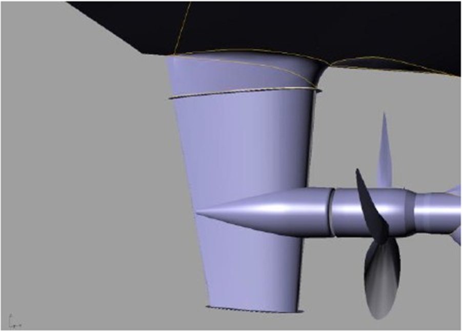
Example application case hub cap and rudder bulb.
The effect on the hydrodynamic propeller and shaft forces has been investigated by comparison of results of hydrodynamic calculations without and with the hub cap and rudder bulb according to the approach described above. The following conclusions were drawn:
Because these ESD types’ concern down-stream installed ESD, the effect on the average propeller and shaft forces is negligible.
A small reduction of the harmonic forces and moments is observed. This will reduce the propeller excitations, having a positive effect on whirling and torsional vibration behaviour.
The added mass on the propeller assembly due to the extended hub cap can have an effect on torsional vibrations, whirling and alignment calculations. However, the mass increase is low and the effects are expected to be insignificant.
Application of the hub cap and rudder bulb may have an effect on the rudder. Investigation of this effect was however not part of the scope for this application case.
Installation of this ESD aims to save energy by re-directing the propeller post swirl flow by fins installed on the rudder. Re-direction of the flow generates a thrust force on the rudder fins, helping to propel the vessel. An example of rudder fins (not the investigated example case) is depicted in Fig. 3. For this example case, application of rudder fins on the HTC-2 container vessel is considered.

Example application case rudder fins.
Also for this example application case, the effect on the hydrodynamic propeller and shaft forces has been investigated by comparison of results of hydrodynamic calculations without and with the rudder fins. Since this concerns also a down-stream installed ESD, the results of the analyses are similar to the results described above for the hub cap and rudder bulb.
A PBCF is an ESD that consists of a modified propeller hub cap with fins. It improves propulsive efficiency by weakening the hub vortex (also called propeller ‘swirl’) and recovering kinetic energy from the rotating flow aft of the propeller blades. Weakening the hub vortex decreases propeller resistance and manifests itself as increased thrust. The deflection of the flow aft of the propeller by the fins reduces the propeller torque. A 3D rendering of a PBCF is presented in Fig. 4. For the investigated example case, application of a PBCF on a Fincantieri container vessel is considered.

Example application case Propeller Boss Cap Fins (PBCF).
Also for the PBCF, the effect on the hydrodynamic propeller and shaft forces has been investigated by comparison of hydrodynamic calculation results without and with the PBCF. Although this also concerns a down-stream installed ESD, the results of the analyses are not comparable with the hub cap rudder bulb and the rudder fins. Because the PBCF is directly mounted on the propeller, the hydrodynamic forces on the PBFC are transmitted to the propeller and shaft line. The following conclusions are drawn from the hydrodynamic calculations:
There is not a significant change of hydrodynamic forces acting on the propeller itself
Due to installation of the PBCF, there is an increase of the thrust but also of the other components (both forces and moments) acting on the shaft line.
Installing a PBCF also adds mass and inertia to the propeller assembly.
The estimated average added inertia is 0.6%, maximum 0.8%
The estimated average added mass is 4.2%, maximum 4.9%
The added mass can affect the torsional vibration and whirling behaviour and alignment calculations. For torsional vibrations, the following effect is estimated for 0.8% added inertia:
Critical speed will decrease by approximately 0.25%
Torsional stresses will increase by approximately 0.8%
A pre-duct increases the propeller efficiency by re-directing the flow to provide a pre-swirl wakefield to the propeller. The pre-duct that has been investigated as an example application case, concerns a special type, designed and investigated by MARIN [1]. This ESD is called a BSD and is effectively a combination of a semi-duct and a pre-stator, see Fig. 5.

Example application case Pre-duct.
For the investigated example case, application of a BSD on a streamline tanker is considered.
Hydrodynamic calculations performed with models without and with BSD have been used to estimate the influence on the hull outfitting items and more especially on the propeller blades and shaft line. Because a pre-duct is an up-stream installed ESD, a more significant impact on the propeller and shaft line can be expected.
The main results of installation of a pre-duct are:
Lower fluctuation of blade forces
Significant difference for secondary shaft lateral and vertical forces and moments
Based on these results, the following effects on compliance with rules and requirements are identified:
Torsional vibration and whirling analyses are positively affected, because blade force fluctuations are reduced, resulting in reduced propeller excitations.
Alignment is affected by the changed shaft forces. Estimated, based on changed vertical force & moment:
Aft stern tube bearing vertical load will decrease by 2.2%
Aft stern tube bearing misalignment will decrease by 0.04 mRad
The maximum stress in the propeller shaft will increase by 9.3%
The working principle of a Pre Swirl Stator (PSS) is similar to a pre-duct; the propeller efficiency is increased by re-directing the flow to provide a pre-swirl wakefield to the propeller. The investigated example case concerns a pre swirl stator that is installed on an Uljanik bulk carrier, see Fig. 6.

Example application case Pr-Swirl-Stator.
For the analyses for the propeller blades and shaft line, the same approach was followed as for the other example application cases. Hydrodynamic calculations on models without and with pre swirl stator are compared to determine the influence of PSS installation.
The results of these analyses are similar to the results observed for the pre-duct:
Lower fluctuation of blade forces
Significant difference for secondary shaft lateral and vertical forces and moments
The effect on compliance with rules and requirements are therefore also comparable:
Torsional vibration and whirling analyses are positively affected, because blade force fluctuations are reduced, resulting in reduced propeller excitations.
Alignment can be affected by the changed shaft forces.
For the application case of PSS installation, also the effect on the rudder was analysed. CFD calculations on models without and with PSS are compared to find the difference in resultant rudder forces, see Fig. 7.

CFD calculations without and with Pre Swirl Stator.
The PSS installation leads to increase the resultant rudder force of 44% in steady flow and with the rudder aligned with the propeller. According to the classification rules requirements, the rudder forces shall be considered for a rudder angle of 35°. Additional analyses would have to be performed to determine the influence of PSS installation in this condition.
For the two up-stream installed ESD; pre-duct and pre swirl stator, also the impact on cavitation behaviour on the propeller blades has been analysed. Wakefields derived from CFD models without and with ESD have been used to make the cavitation calculations. The cavitation behaviour of the possible tip and hub vortices are not included in the analysis.
It can be concluded that there are no significant changes in cavitation behaviour on the propeller blades due to application of the analysed ESD. Only for the PSS, a marginal reduction in cavitation volume near the blade tip around the top position is visible when applying a PSS, see Fig. 8.

Cavitation behaviour around the top position for the bare hull (top) and with PSS (bottom).